European grid voltage very high, quattros went off

in the grey future you will find a small blue box … completely weathered with a coil and a capacitor inside … All the researchers look at each other questioningly … :thinking: :thinking: :thinking:
to be continued …

Some more data

… und so schön auf deusch :slight_smile: … da hab ich ja was zu lesen … danke :+1:

Good morning,

These smaller stabilizers are only used directly on the grid and then directly to an electric consumer, never to an inverter.
That would be the first one, one inverter in front of the other one…

The Generico-SEV M3-30 from Adajusa is a 24KW/30KW 3-phase voltage stabilizer is in my range.
As mentioned these bigger ones are servo motor controlled, and used also directly to the consumer and are pure sinus.
The downside of these things is that these are not so energy efficient, costing a ton of money per year, just on standby alone.

I do not see any advantages from the above discussion, other than again a bad build piece of equipment that prematurely fails after a little time of use, thanks Alex for the inside photo.
Then, the technology they use in these single phase Chinese things is just “chopping” the voltage, well, I use 3 “choppers” to control my 3-phase water coils proportionally, Fadisel R-27 (2 older and 1 newer PWM one), these do exactly the same, and cannot be used for sensitive electronics.

I still go for a simple relay and an over/under voltage switch, cost effective, proven electronics, propper brands, many to choose from, no extra space, bulletproof, so to say.
Or if there is another way to switch off the grid through a Victron relay/software, then I will do that, not found yet btw.

Regards, Jeroen.

Just a thought… maybe for ones that have an energy meter put in front of the inverter…
That energy meter is still providing info about grid voltages, even if the Victron inverter’s AC-IN relay disconnects, right?
So maybe a small script that is taking the info from the energy meter dbus paths and connect or disconnects accordingly the inverter’s AC-IN relay ?..

But if you think about it, even the inverter is still having the AC-IN info, even if the AC-IN relay is disconnecting the grid…
So, not even the need of an energy meter…

Of course, the script should disconnect the grid through AC-IN relay before the voltages that will trigger the high voltage alarm…

Good morning Alex,

Indeed, I was just checking in VE again, no result, also through the Cerbo it doesn’t have this option to choose input voltage to switch one relay.
Also the led alarms assistant does not have high voltage.
I tested quickly with an ET-340, also no option to switch a relay by the Cerbo.

Yep, inside the wiring to the control board is connected before the input relais, this, of course, is also for the “anailzer” function before switching the grid through and/or in charger mode.
There should be the small relay to switch that off…in case of overvoltage, not even an amp goes there…but thats an modification…losing the guarantee…but the inverter then runs on DC.
We’ll have to check further and see what’s best.
It would be nice to have an high voltage assistant (with timer) with the K1/K2 relais or internally, that would be the easiest solution integrated in the inverter, this as some installations do run stand alone.

Regards, Jeroen.

@Jeroen2 i brought these parts in because i really thought they were the oldfashioned magnetic regulators.

Fast
Cheap
Indestructible

Mea maxima culpa

Hi Jeroen,
I was talking about a script or a Node-Red flow. Easier with Node-Red if you have the large image installed.
From there - Node-red - you can choose an input node that provides the AC-IN voltage.
And then, based on a comparison function, you can drive through an output node the Inverter’s AC-IN relay. (or Cerbo’s relay)

Good afternoon Alex,

Yes, that is all possible as you say, but that’s for 1000nds abracadabra, my point of view is that it should not happen and should be solved in an assistant (standard) or in a function in a GX (in general).
The best would be as you said before, an ET-340 (or similar) in front of an inverter with the relay in between, then in the GX an option to switch the relay (and with switch back on delay) during over voltage.
Even better, a small relay what switches off the primary power to the control board internally of the inverter.

Looking around for an overvoltage relay the last 2 days, wow, these companies sell tons of that stuff at the moment, and nobody complains…

They sell complete units up to 63A (mostly Chinese stuff), relay integrated, no, not for me, none of those, when these fail, no manual control.
So, it will be for now, a 3-phase overvoltage switch that switches a 40A 4-pole NC relay with a manual switch as well.
Only to open when energized, to save again energy not to have that coil energized a year long.
This, as security, when the overvoltage switch is broken , the energizing contact will be open, so nothing happens other that the inverters switch off again temporarily with overvoltage, the big relay can be switched on/off manually as well, handy for testing.

I think that’s the temporarily/permanent solution for now, till Victron engineers make that available in GX or in the inverter with an assistant.

Another thing I will check is the 2 AC inputs of a quattro, I forgot if the main board only gets its power from AC1 or 2 as well, if so only from 1 then I just switch grid the inputs, running only on DC power supply all the time.

Of course, a Multi keeps the same issues, please Victron, have a look at this, voltage is rising drastically in Europe, what to do?

Regards, Jeroen.

Good afternoon Ludo,

I checked those, indeed, not made anymore, these were more to stabilize voltage swings and frequency swings, then the voltage was still our “famous” 220V.
AND, we still had the “magnetron” TVs, mainly working on frequency and high voltage, 158 vertical, 258 horizontal lines if I remember well, 3 by 4 it is called today?
I grew up with black and white TV btw, like you.

Well, I just got in contact with the above mentioned voltage stabilizer company, they say clearly, only to be used in one way.
Meaning, not possible to place in between an inverter which delivers also to the grid as then it will overheat, etc, catastrophic results.

Then, I asked the local technician who is responsible for our grid here, the grid transformers are so big that it is actually possible to use those 2 way, but these babies are oil submerged and way different constructed, and have a fixed ratio, meaning it’s a problem from the HV to the LV stations transformers, and even, he says the generation centrals in general…
Instead of putting more HT cabling in Europe and/or thicker ones, they raise the voltage to transport energy.
Mainly, due to the “boom” sales of electric cars last years and a big delay in changing HV cabling.
He says, this problem will be there for sure till 2035 due to the electric car sale agreements.
I’m flabbergasted, in the meantime we “normal people” burn our household equipment…and nobody complains…

Regards, Jeroen.

Ofc they’re still available

Good afternoon,

Yep, not really bi-directional, I’ve checked, besides, my wife will deforce me, too many euros, no, as written above, overvoltage switch with relay for now…

Regards, Jeroen.

I don’t believe in ess/dess, so it does not have to be bidirectional.

Yes, they cost money, life itself is expensive.

Good afternoon Ludo,

I understand your idea, but it’s not working anymore today.
Its not about what we believe, its about what is happening with the grid as we speak, ESS, DESS, no grid feed, but used as back-up (not to have a generator), we all hang in a way on the grid in europe, right?
The issue is there…
You carry in your mobile home such device in front of your inverter, no, nobody does…
Does a normal household with or without inverters and/or batteries have to buy this, no…it’s a grid issue, and our very best Victron inverters (and some other brands) cannot cope with 270v.
The basic problem is the grid …and so your grid provider pays you a voltage regulator, no, they don’t,…
Do not forget, we all have to go green, cities cannot of course…burning their home appliances without knowing.
Your solution is consumer oriented, that cannot be, as we buy consumer products, every day, your TV, with 270v will last a day or 2…

So, I hope I catched the point, these voltage stabilizers are from grid to consumer, not to be used 2 way with our inverters to deliver to the grid!

Regards, Jeroen.

Yes, if i can get one i will

The victron should disconnect from grid above 253 volts here in the Netherlands. This setting is also in veconfigure. I believe I saw it disconnect once, when the voltage became 254 volts the multiplus switched to inverting mode.

For real overvoltage I installed a OBB V20-C surge controller at the incoming grid connection which will trip the main breaker.

Good morning Jeroen (naamgenoot),

Yes, such devices are here (Portugal) mandatory in TT, earth pin inhouse only and/or various earth pins in and around the house.
For the grid side (input inverters) we have the Hager P120 (3x) and the P150, these should keep the phases and neutral on 255V when there is a lightning strike.
Under normal conditions and the voltage goes over the 255V nothing happens, only with a strike.
On the output of the inverters we have the Hager SPN465R, what will keep the neutral on 255V and the phases on 275V.
This as not only a strike can come through the grid but can also come from PV panels, outside lamps, buried cabling, even through the earth pin, etc.
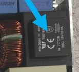
The OBO V20-C limits the phases at 280V and the neutral at 255V.
There are many brands for that, but these do not solve the overvoltage we experience.

Then, when you set in VE, the input voltages as you have, indeed it will go to inverter control, however, the control board still gets the grid voltage (and also measures), if it comes above the 265-270-isch Volt than the inverter trips, as I experienced, see above.

For your insertion to the grid, the grid is the grid, you must raise the voltage (normally plus 3-5V) to be able to insert to the grid, just set the maximum voltage to 258-260V instead of 255V, check how that goes.
I do not insert to the grid, I have my own micro-grid at 230V, at full PV power on the output, the output of the inverters are still 230V, always, that output the main inverters regulate perfect, during full PV and starting heavy equipment we see fluctuations of maximum 3V only, very good.

Therefore I say that the people with ESS, DESS and direct grid connected have now big issues due to the high grid voltage, damaging many household appliances.
And even, people like me, hanging on the grid for backup only, any inverter will trip above 265-270-isch Volt anyway as it primarily feeds the control board.
Only, the real off-grid inverters run on their secondary power supply from the battery.

Thats, why we want to place a simple relais in between the grid and the inverters, so it keeps on running when very high voltages occur.
Maybe only once or twice a year now, but it does…

Regards, Jeroen.

Good afternoon,

We have been busy…to see this AC power supply in an inverter.
This is the board from a 24V Quattro, see below.

The top circle above the big capacitor is the +24VDC battery power supply with a “littelfuse” T7A fuse right below to it, here taken off btw.
The 2 small holes besides the big capacitor is the battery -24VDC.
The bottom right circle is the AC1-in AC power supply with only N and L.
The bottom left circle is the transformer from the AC supply, and clearly it can be seen 260V in and 17V/10VA out 630mA fuse.

So, indeed, somewhere above that voltage, things will happen.

Regards, Jeroen.

If you simulate a grid blackout does the system invert as it should?

What is your grid code and or grid settings?
What batteries do you have?

Some other basic information about your system would be helpful too. Like what batteries do you actually have.

As a user of an excessively variable grid system the use of SPDs with a combination of programmed tight grid voltage tolerances helps to not have that crazy voltage passing into my home appliances.

Good morning,

Yes, when I use VE and set the high voltage lower (to simulate) than the grid, it ignores the grid and goes to inverter mode.
If I switch off the grid it goes to inverter mode.
We do not inject to the grid, we use it as a generator only, already 11 years, in VE “None”, “feeding energy from DC to grid not allowed”.
The grid is only switched on with a low SOC of the batteries by the contacts of the 3 BMVs and the relay of the Cerbo (for remote control), all4 contacts go to a relay (can be switched locally) which then goes to the aux1 input of the Master Quattro.
Then the assistants, switch the grid on/off, on low voltage of the batteries and if high load occurs over a certain time, nothing special there.
So, that works perfectly.
The batteries have nothing to do with it, lead acid, 4200AH 24V, yes, very big ones and they are just fine.

When you look at other inverters inside, most of them have the same little transformer on the AC1-in, well a Multi has only 1 AC-in.

My setting in VE is 270V high ignore AC-in, 265V reconnect AC-in, above 270V-isch, the inverter switches off completely instead ignoring the AC-in only and shows me the led alarm overvoltage, only orange bulk led on, alarm 18 in the Quattro manual alarm list, not showing in VRM, alarm mail, not even on the Cerbo, only visual (by luck my neighbour was there).
It showed however by mail, Cerbo and VRM, alarm 3 and alarm 14, coms fail in bus basically, since one or more quattros switched off of course.

Regards, Jeroen.