ESS and Charger behavior (Backup generator for Power outtage)

Sorry, i don’t know how your comment should help…
As mentioned above, the problem is that as soon as a grid code is set, the inverter does not work anymore with a AVR generator even if the input is configured as generator.

And we do not need AC out 2…

I always have a 1.5kw heater (resistive) connected to my conventional generator, without this my multiplus 12/3000 will not connect.

this sounds like otherwise the input frequency is too high…

No, its probably the waveform.

But as i have a solution i don’t really need an explanation to be satisfied, I’m not that nosy :wink:

Also think it could be related to the waveform. That with the heater as a baseload is the same thing, but likely more crude than the thing with the waveform-sensitive ups and the freewheeling compensated induction-motor i stated.

Question - did you already had a look on the waveform generated of the AVR Generator with an oscilloscope?

And did you try it with disabled UPS mode? As i stated - disabling it does not remove the function of a battery backup if power fails - it only prolongs switchover time a little bit - but with the benefit of being less picky regarding the input waveform.

I´m with you that the charger-only variant is no real solution :joy:

I did not but AVR generators usually output a perfect sine wave by design (at least if we are talking about high quality generators)

I did, no changes

I am still convinced that the problem is that while AVR gensets output a perfect sine wave (the grid consists mostly of AVR generators) they do not output a perfect frequency and there the inverter makes a mess…

I will now try to get a official answer from victron and see what they say

This is so far the official answer from a Victron dealer:

If a generator is used as a power supply, a MultiPlus will work without any problems, then of course do not use a grid code as it is not connected to the grid.

*If there is a grid, then use a Quattro with an extra input for an backup generator. *

Grid and generator on one AC IN do not work.

In this case, at least the generator would have to supply a perfect current equal to the grid and this constantly, then it would perhaps be possible.

Wich i replied with:
Thank you very much

I have made the following test:

(with both a 100 kVA and a 20 kVA generator)

Grid code Germany, AC in 1 LOM set to generator, generator connected to AC in 1.

But it did not work!

And then added this information:

I did the test with 3x quattro 48v 8kva (1 per phase).

Then I did the test with 6 5000 multis (2 per phase).

I only tested the multis with a 20kVA AVR generator, the generator oscillated extremely (0-100%)

I tested the quattros with 100kVA and 20kVA, the load was extremely asymmetrical and not constant.

Currently waiting for a answer…

i wanted to do a test with the multis…


but i can’t have ESS enabled without grid code…

How should i setup my system so it only charges the batteries from MPPT or power from AC out?

As far as i can tell, the culprit is “…or power from AC out?”. Feeding/Charging on the AC out is an ESS thing, specifically the function of supporting AC coupled PV on the AC out. And for ESS a grid code mandatory. And as soon a grid code is in place, you would probably expericence your problems with the generator(s) again. :slightly_frowning_face:

But nonetheless i would have a look at it with a scope or power quality anazlyzer, especially at the region of the zero-corssings.

Because of a theory/possibility:

While doing their ESS thing the Multis/Quattros have to keep in sync with the power feed somehow. Althought i dont´t exactly know how victron does it, the usual was is by zero-cross detection, usually by an op-amp based contraption often in combination with some hardware or/and software based refinement. At least so i did it for the thyristor rectifier synchronisation in my inverter…

Imagine the following: If you have glitches, spikes, small harmonics or whatever in the zero-crossing region it could cause early or late firing of the zero-cross-detection and thereby causes the system to mis-sync. Even a one degree phase angle mismatch could have huge implicatons in the resulting current draw and thereby loading condition. And it could cause the described unpredictable non-symmectric oscillating power draw.

Although i think you already understand what i mean, here a (perhaps slightly extravageted) picture.

Without ESS/Grid-Code there is no need for the whole grid-parallel and synchronizing part - the Multis/Quattros simply take what they get and use it. Therefor this couldnt happen in the first place and could be perhaps a reason why it works without problems without a grid-code in place.

At least with the Quattros, feedback from AC out works even if no ESS is configured.

I will get a oscilloscope and continue my research.

I just also had another idea.

With the Multis i always had the grid present but set them in inverter mode so it disconnected from the grid.

But i have a theory that they probably stay in sync with the grid all the time even if disconnected. This would obviously result in frequency shifting what the generator cannot handle…

Will give feedback once i have a oscilloscope in my hand.

Didn´t expect that feeding from AC out without ESS works. My bad - and good to know! :slight_smile:

Your theory about staying in sync with the grid als long as it is present on the input even when disconnected absolutely makes sense. With this, the system could switch near instantly to grid if necessary instead of needing to go to the sync process. Could also be verified with a scope and two siutable differential probes.

today i did tests with a osciloscope.

first of all. if you just put the inverter in Inverter only mode, it stays always in sync with AC in.

the only way to get it out of sync is by physically cutting the power on AC in, then it goes to solid 230v and 50Hz

already being happy i did another test with the generator on AC-out… without luck. the genset synchronises, closes its circuit breaker and as soon as this happens, the AC out is no longer a sine wave. it is more a Erinaceidae…

meaning the 50Hz remain solid but the voltage cuts at about 120-180v. causing huuuge currents on the generator. The inverters turn off after a very short instant because of overload…

so what we know now:
ESS/Gridcode and generator, no matter if AC in or AC out does not work.

no ESS/Gridcode and generator, no matter if AC in or AC out works

As long as we are Grid Parallel it does not matter if the Generator is on AC in or AC out and it does not matter if ESS/Gridcode is enabled or not.

1 Like

Interesting.

Confirms the theory that the inverters stay in sync with the grid as long as it´s connected to the input, even in inverter-only mode. Did test this out of couriosity yesterday on my system – same result.

I must say i have a bad feeling about feeding via AC out with ESS/grid-code. Think it wasn´t ever made for genset feeding where the inverters are the grid forming part. Probably works fine for AC-PV feed because that can adjust freq. and phase near-instantly and a genset cant. I think it works without grid code / ESS because in essence you take the AC in relay out of the equation. It does not have to sync, it simply takes what it gets.

Question – did you scope the test setup with the genset on AC-in with the genset as grid-forming unit and the inverters with grid-code “Generator/Other” and ESS (but without LOM!) and UPS mode disabled? And only the generator – no grid physically connected on the other AC-in.

It would be interesting what the waveform of the genset looks before and after sync when the system tries charging in this config. Also pictures of the waveforms would be nice.

FYI – my setup for feed switchover is as follows: I have a contactor before each AC-in. They are interlocked so only one can be closed at the same time. I know the Quattros should do that internally but i´m a friend of redundand safety and even more safe interlocks. So if i switch over to generator on AC-in-1, the grid on AC-in-2 gets disconnected and vice-versa.

Additional info although it´s unlikely that it has somthing to do with it - but this are my settings for reactive power regulation on my quattros. (cause the grid company wanted it that way…) It is also active for my generator input because i have the VDE grid standard on both inputs, only without LOM on AC1 for the generator:

“Standard” would be cos. phi 1. As far as i know it´s for stabilization purposes that the inverters behave a bit inductive or “underexcited” if the voltage is high and a bit capacitive or “overexcited” if the voltage is high.

Hello guys

after spending 2 full workdays together with my colleague (we are both electric engineers) with the setup of 2 Multis per Phase (so a total of 6) i would like to give a update:

so far victron is refusing any support (or at least not providing helpful information)

so we tested a lot of things. what i can say is a 20kVA Generator on the AC in does not work, no matter how the inverters are configured, we tried really everything.

the only thing that worked to charge up the batteries was removing the grid code and ESS from the configuration and connecting the generator in parallel mode to AC out.

however that is ofcorse no solution since i cannot use the batteries for self consumption anymore.

what we found out is that the battery charging behavior changes a lot as soon as a grid code is set (even if set to the Danish grid code where LOM is forbidden (no idea why))

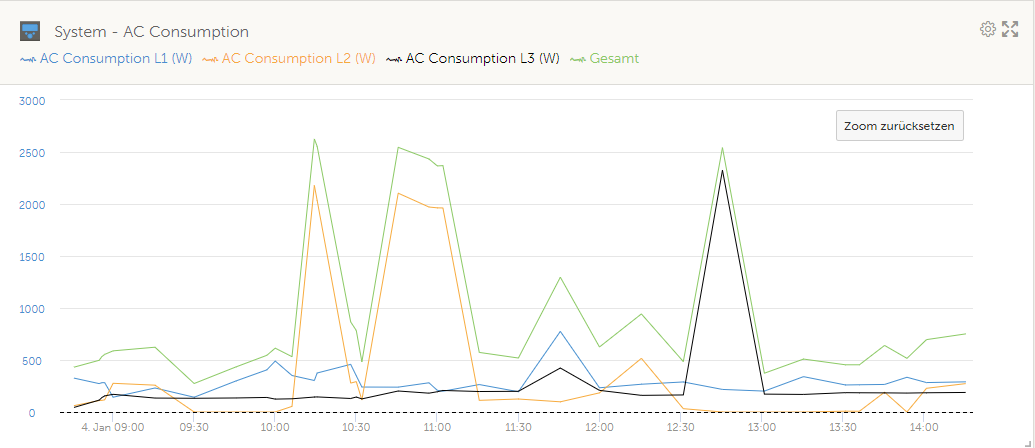
This screenshot is charging the batteries without a grid code. as you can see, the inverter goes to a constant power and stays (almost) rock solid to the target power, even if the load is changing.

However if we take a look at this screenshot, we see that the Power is always swingig up and down (the target “ESS Setpoint” is lowered slowly over time from externaly so don’t be confused why it reduces the power from 7 to 5 kw. it is meant do do so but on a linear rate)

So the charger seems to behave even like this if there is no grid, ending up in a unstable RPM of the generator. If the Generator is on AC in, it starts to “swing” and once it reached 49.8 or 51.5 Hz it disconnects. If it is on AC out, the generator also starts to swing and trips its circuit breaker or the inverters go off because of overload.

next thing we found out was, that while the inverter is syncing on the Generator (gen on AC in) the sine wave of the generator starts to look like that: (to quote my buddy: “even a child could draw a better sine wave”) and no, the Generator is not faulty! i can power the house having a perfect sine wave with some inductive loads like Heatpump pulling 12 kW (this is measured before the inverter closes its AC In Relay)

and this is how the current “sine” wave looks like while loading the genset (Target Power was 20A but long before it reached that point it disconnected):

The oscilloscope screenshots are with no ESS, no grid code, Genset on AC in EXACTLY how victron advises to do.

I was then ready to give up grid feedback and setting up the system without ESS and having a external PLC limiting the input current and using Power assist and coded my own self consumption algorithm. Until i found out that Power assist does not work with less than 6A per inverter input.

Long story short: if no other solution comes in (hopefully it will) i will sell those inverters and look out for a competitor solution that keeps up with its promises.

I would be very thankful for any input or idea how to go around this issue. all i want is a BESS and being able to charge the batteries with the genset in a power outage (and taking a 48v charger for this really makes no sense for me)

Hello Kevin,

wow – that current waveforms on the second screenshot look really crazy. But regarding this i must say i never scoped the CURRENT waveform of my setup while charging – only the voltage waveform i posted above. A buddy of mine has a power quality analyzer. I will ask him to borrow it for measuring the currents on my next “charging run”. When i have it, i will post it to you to have a comparison. But can take a few weeks.

I charged today and have a two short videos a few screenshots for you. I have some power fluctuations as well – you can see that on the second video on the amp meters slightly swinging up and down all the time.

First the display of the cerbo while charging:
[EDIT] this video was not from today but from the last time. But everything the same.

And here the generator/inverter meters:

Here a few corresponding screenshots from VRM:


At some times the quattros are limiting the charge current due to the set input limit of 13A per phase. You can see that on the load and battery screenshots. The “ditch” on the generator screenshot around 11:45 was caused by a woodsplitter that sucked more vars than watts :sweat_smile:

A question - do you have implemented a charge current limit on the multis in VE Configure?

If not, you can try this in addition with an input current limit so that not only the ESS setpoint is the regulating factor. Would try for example 20A charge limit on each Multi which would result in approx. 6500W total and also an input current limit slightly above for example 13A for a test.

I can only tell from my experience that in my case the quattros are doing EVERYTHING to not exceed the input current limit. They react quasi-instantaneous when someone engages a heavy load. You can see this in my screenshots above that the corresponding phase was unloaded for charging if loaded otherwise on the load side.

And another question - did you try test-wise charging the batteries from the grid with the power quality analyzer attachted for scoping the current waveforms? Would be interesting if the Multis are trying to draw the same kind of crap-waveform or if that only is the case when charging form the genset.

Thank you for your videos.

no i didn’t but the problem appears a long long time before any charge limit would come in mind (the genset just starts to push power / gets loaded)

indeed, this is a great idea, i will take the osciloscope again from my employer next week with me and give it a try. but i would be impressed if it would look the same i don’t think these multis are doing the same to the grid as they do to the genset. i am still thinking that the multis are messing with the frequency wich the genset can’t handle and results in that crappy waveform.

Great that you have some real analog gauges. what i can say is yours look very stable, the 100kVA genset we used for some tests has the same gauges and they were always jumping much more around…

Would be ineressting to see what would happen if you connect a Synchronous AVR Genset to your system. i am sure it would also not work… (otherwise i would realy question my skills :laughing:)

Sorry – i don´t have a suitable synchronous AVR genset in my posession or in my reach and i´m a bit hesitant to fiddle around too much on my perfectly working system. But i´m pretty sure it would make problems too.

As a sidenote – my homebuilt asynchrounous inverter genset was there before my victron system. It was NOT purposefully built for charging with the quattros. What sould i say - it was my „corona-project“ :blush:

But after all you have wrote and tried out my thougths were “mabe it´s an exceptionally lucky coincidence that i´ve done it this complicated and very unconventional way…“

And btw – i like analog meters and gauges. Why? They work. No digital crap integrating over seconds and telling nothing :laughing:

But back to the facts – i actually have an idea how to test that out and probably find the cause. A friend of mine is building his victron system right now with three MP 5000/48 in a three phase configuration plus a fourth MP 8000/48 to charge from a genset.

He has two generators – a 3kVA single phase sync. AVR and an asynchronous 7,5kVA three phase genset. Both gasoline. I designed/built an inverter for him in principle working like mine but recombining three phases or two gensets into one “strong” single phase. (Dont ask why – he was fascinated by my inverter, wanted it that way and asked if i could do it - so i did. :man_shrugging:)

If his system is ready (i think mid to end of february), then we could test-wise setup his MP 8000 with a grid-code, set up the power analyzer and test it with…
a) the single phase AVR sync. genset
b) one phase of the asynchronous genset
c) the inverter

If the problem is frequency-related, then only the inverter should work. If it is waveform-related, then the inverter and asynchrounous generator should should work.

The test would be only single-phase, but should nevertheless be meaningful with regard to the overall problem.

Regarding the thing with the input current limit and charge current limit – i know that the problem manifests before right now. My thoughts were that the system is told in advance where it´s operating limits would be and how much headroom it has so it can regulate accordingly.

You can see the limits have an effect how the system regulates when you look on the graph how it ramps up charging power - the first 60-70% “steep” and rest “slow”.

Hello there, i would like to give the last update about this.

Victron still refuses to give support. The only way to reach them is via the dealer and the “answers” they give are completely useless.
Mostly “try this, try that, mabye this could make a difference”
Last answer was that the 2 gensets are faulty (wich they are absolutely not)

so i decided to give up. i Returned the full setup to my dealer and ordered a solution from a competitor.

Thanks to everyone trying to help me.