Does inverter-caused Hum harm the battery?

Per the Subject… I have a small off-grid system consisting of 500-ish watts of solar, a SmartSolar charge controller, a Phoenix 12/500 inverter, and 315AH of LiFePO4 12v battery. There is also a 12 V DC power supply (set for just under 13.5v) that feeds the system at night, preventing the battery from discharging below about 50% SoC so it can serve as a UPS. All is working as expected, but some background before the question:

The initial system build had a much smaller battery, about 21AH of tired AGM. It was enough to keep the system stable, and to cover for short mains outages at night. But I found that there was a LOT of AC ripple on the 12v bus, caused by the Phoenix inverter when it fed a non-resistive (0.8 power factor) load. That ripple fed into all of the DC-powered parts of the system, causing a lot of hum on the audio components. The official Victron “solution” to this was thicker wires and a bigger battery, which at the time was outside my cost envelope. My solution, instead, was to add a filter - a large inductor in series with the positive feed to the inverter, with a large capacitor directly across the inverter input terminals. The parts were in the proverbial “tin box” in the garage, so zero cost. That reduced the ripple at the battery to negligible levels, and cured the hum. Measurements at the battery showed nearly zero AC current.

Fast forward to today. Now that I have some 300AH of really stiff Lithium battery in place, I thought I’d try removing the filter and see if the hum returned. Good news, it did not; all is still as quiet as with the filter, and I also eliminated the small energy loss of the filter itself.

But.

As expected, the AC load on the battery has returned. With about 136 watts of load on the inverter (at 0.8 PF), I see 5.5 AMPS of AC current at the battery terminals, as measured by a clamp meter. Because the battery is so stiff, that doesn’t translate into any significant AC voltage (so no hum), but I am concerned what impact the pulling and pushing 5 amps into and out of the battery at 60 hz, 24/7/365 days will have on the battery life.

Will an AC “load” shorten the life of a LiFePO4 battery? Alternatively, if I put the filter back in, will that shorten the life of the input caps in the Inverter (since they will be taking the brunt of the non-resistive load-induced ripple)?
In a word, No.
The Battery will cope with this, due to the low impedance.
However, I would like to point out that the AC current from the battery to inverter will look like a half wave rectified AC, and this is superimposed on a DC current too. So you won’t actually be ‘pushing’ any current back into the battery. At the low point of the complex current wave form - coincident with the output current waveform zero crossing, the battery current will still be powering the inverters internal dc loads. As the Ac current reaches the maximum - on either positive or negative cycle, then the battery current will also increase to maximum, giving an AC current superimposed on the dc current one would expect.
It would be possible, as you did, to add a filter with a large inductor and reservoir capacitors to remove this AC current component, but this would add cost and volume to the product. The filter capacitors would also be subject to a high ripple current - this would have a negative effect on the capacitor lifetime.

Hi Mike,

Thanks for the reply, and sorry for the delay (been busy and out of town). The low battery impedance is definitely a benefit, but I believe that only affects charging efficiency by not turning the current into heat. There’s still the chemical mechanism - what makes a battery a battery - that I’m more wondering about.

Good point about the superimposition of the hum and DC current. For much of the day, however, the DC component is far lower than the measured (*) inverter hum, as the DC power supply is supporting most of the load. Only during the 3-4 hrs of solar charging is there a solid positive current going in (up to 14+ amps), and only for a short time after the panels go into shade is there more than about two amps coming out. For the rest of a typical day there’s just a slow (few amps) drain as the battery and DC power head toward equilibrium. My concern regards that slow discharge time; if the AC component exceeds the DC component, the battery would be subjected to very rapid (60hz) charge / discharge cycling.

A question… Does anyone know how big are the filter caps at the DC input to the 500VA Phoenix inverter? The cap I used in my filter was 48,000uf - it’s what I happened to have on hand. I’m wondering, is that big enough to keep the inverter’s caps from being damaged? The inductor isolates the ripple from the system and battery, keeping it local to just the capacitor and the inverter itself. But the inductor I have also limits the total power the inverter can output to something around 160w, and it burns a little bit of power (as heat), so it would be nice to eliminate the filter if I can.

(*) A pre-posting update. I’ve been taking more measurements as I write this, running experiments, and generally noodling on what I am seeing. I’ve convinced myself that the AC current measurements I reported earlier are not to be trusted. Easy test, I change the DC charge or discharge component (only) and I see the AC reading change substantially. I expect it should not. The DC reading seems good (it matches the BMS and SmartShunt), but the AC reading seems to include AC plus some unknown portion of the DC as well. No way to separate the two.

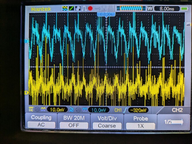
Since I have a 500A SmartShunt in front of the battery, I’m thinking a better test than the clamp meter is to put an oscilloscope across the shunt. I’m seeing about a 10mv P-P signal there… What is the resistance of the Shunt, so I can compute the AC currents?

Channel 2 (upper trace) is the (AC coupled) voltage ripple at the battery (100mv/div); Channel 1 is the DC voltage across the shunt (10mv/div), representing the current through it. This is with about 12 amps discharging from the battery, 133w load on the inverter, and no (zero) charging sources active, so it’s surprising that the AC current appears to spike negative. That would indicate a momentary net charge, which is nuts. If I mentally filter out the spikes, a smoothed waveform does appear to stay positive, so this might just be a measurement artifact. (Before you ask, the scope is a battery-powered unit, so no ground loops.) {shrug} Thoughts?