Hello. I just rewired the system in the back of my pickup and now the BVM-712 monitor is showing positive current when there’s a current draw (i.e. when the fridge/cooler is running) negative current when the system is charging (i.e. when the engine is running and the alternator is charging the battery)
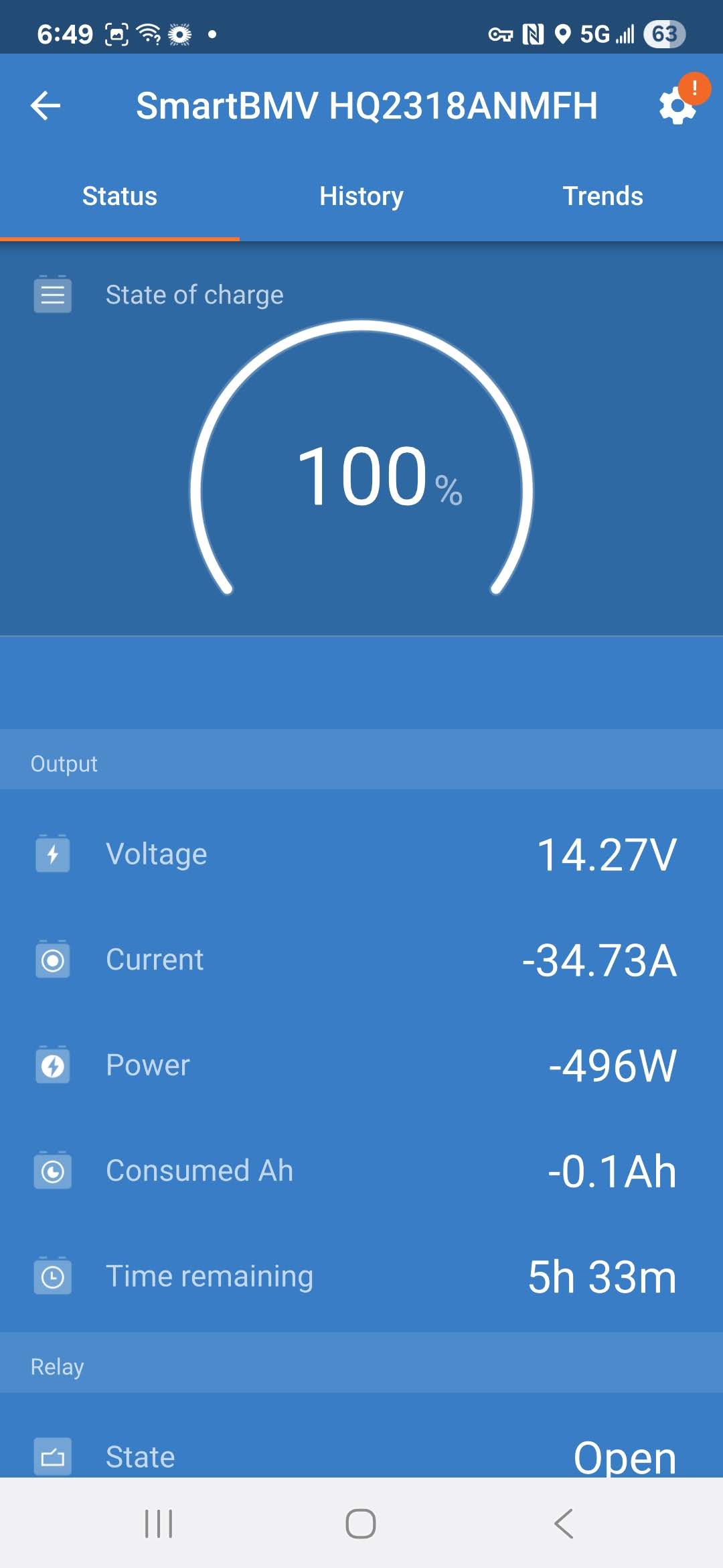
Here’s an image of the app when the fridge is running
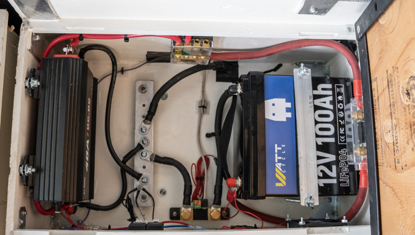
Hopefully it’s not too busy for you to see the negative lead from the battery goes to the shunt. Then from the shunt to the bus bar which connects to the chassis.
I’ve had this system wired up before and it worked flawlessly. Only then I had a 50Ah battery and in a different compartment in the truck. But otherwise it’s was wired up pretty much the same.
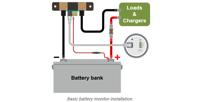
From the manual, it seems i have it wired up the same way:
Thanks in advance
(edited 4 July to reverse the images to match what I was saying. ~+3A when the fridge is pulling power. ~-30A when the alternator is on).
Are the images the correct way round, you say that you see a negative figure when charging. It appears to show a discharge of 34.73A when the fridge is on and a charge of 2.67a when charging?
Julian,
Sorry I haven’t gotten back sooner. Yeah, I had my wording and images backwards. I edited the original post.
I actually started to doubt myself so I re-looked at the photo I took and the manual again before replying and it looks like it’s wired right like @pwfarnell commented (thank you, too).
I’m really at a loss. In my old configuration it worked just fine. I don’t have any photos of it, unfortunately, but I’m sure I wired it the same…oh…wait.
Hmmmm, I just had a thought. I did take their amazingly long data cable, cut it, and then re-terminate it so that I don’t have so much left over. 10m…really.
You can see in the photo that I have a small length of it in the box. That connects to a RJ-12 passthrough bulkhead connector. Then I have another length that goes from there
to the box where I mount the display. Within that box I have an off-the-shelf RJ-12 bulkhead connector with a 6" whip that connects to the back of the BVM-712.
I wonder if I reversed two of the wires at one of the connectors I crimped.
In the manual it looks like there’s a way to reverse the direction of the current measurement (section 7.6.13). But that doesn’t really “fix” the issue if I’ve wired something backwards.
I guess I’ll ring it out from end to end and make sure that they are the same/correct. I didn’t do that because, visually, they looked the same. And I’m pretty adept at making wiring harnesses and crimping RJ-45’s for networking. But I can’t same I’m always perfect.
This is just a guess, but you’ve got that battery on it’s side. Usually the LFP cells which are inside of that kind of battery NEED TO BE UPRIGHT, otherwise you can/will lose electrolyte and risk having a fire.
Please mount that battery upright with the terminals on the top. The cells inside have valves which need to be upright.
Sorry it took so long to get back. Work…long vacation….life and all that.
But I figured it out!!!
While we were vacationing I had an epiphany. If I’ve attached the shunt correctly to the system (which I have reverified a couple times) and the only thing different is the data cable going from the shunt to the BVM, then maybe that’s the problem.
“Why is the data cable different?” you ask. Well, the one they send is 10m long. and in the previous install I left it all intact. But I hated it all bundled up.
In the new install I decided that I have the aptitude to make that cable shorter. So I measured the length I needed and then cut the cable. I actually cut two lengths because I used a bulkhead connector to run it out of the box it’s all installed in.
Having the right tools and patience to make the crimps correctly, I didn’t both ringing it out after a close inspection and then plugging it in and it all seemed to work (until a week later when I noticed the current going the wrong way).
So, reinvigorated from a long vacation, I rung it out. Turns out that pins 3 & 4 were swapped between one end and the other. I have access to three of the four connectors and they were all identical. So either it’s the one I can’t get to or the bulkhead connector is a crossover.
I decided the easiest way would be to make the fully accessible and short cable in the box a crossover cable. This was much simpler than having to move the box it’s all installed in so that I could get to the bulkhead connector and the connector that’s plugged into it.
Anyway, so long story longer…I reterminated one end of the cable with pins 3 &4 swapped, labeled it a crossover cable, and voila! The current now reads correctly.
Thanks all for your help. You may not think it did, but it was a help to have a couple extra sets of eyes to make sure I wasn’t missing something.