@MikeD your ears must have been burning today as expletives came out of my mouth lol, well I finally got round to extending the inverter cable replacing the 70mm2 for 95mm2 it wasn’t as straight forward as I was thinking.
I had two issues, the lug hole at the inverter had to be tapered front and back to allow the lug enough room that it doesn’t have to go in square and the lug just bumps on the thread ribs.
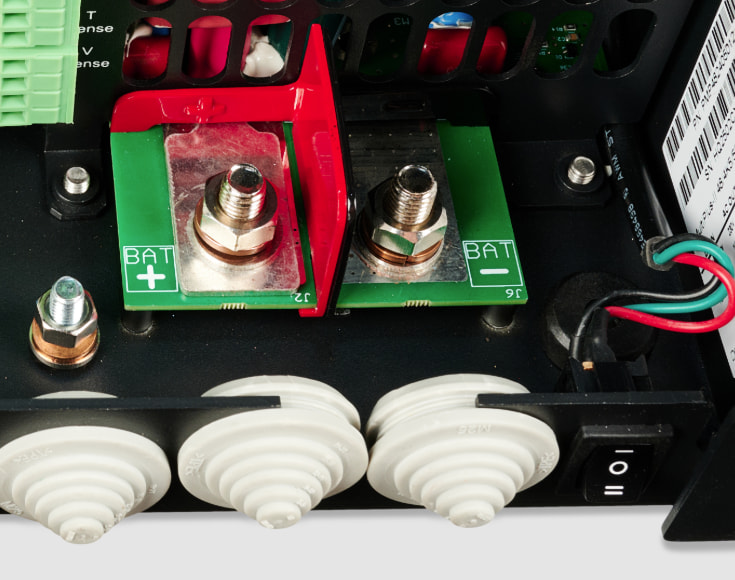
Got that sorted and thought it was smooth sailing good just to connect it to the Lynx distributor my Lynx distributors are the 8mm version, the lugs for the 95mm2 cable doesn’t sit under the mega fuse the lug was to tall so shaved it down just enough it clears the the mega fuses black housing.
Total length of the cable is 3.40meters round trip so well over spec now, which is the way I like it. Thanks for the advice
As we say in Fiji, Wananavu (wonderful).
Yes, I agree that the holes in lugs are not designed to let the cable / lug go on at an angle (in the vertical plane). For this reason, if the situation is tight, I will often use a slightly oversized lug - ie 10mm hole for 8mm bolt. However, your solution is just as good, and necessary when you have already crimped the lug. I like Victron’s approach on the smaller MP2’s where the case cable entry is open on one side to allow the cable lug to go on the bolt square, then worked into the final position. Hopefully this mod will be applied to all inverters.
I have the same issue with my 5KVA and 70mm². The hole is just to narrow to allow the lug to go over the thread.
Is drilling out the hole voiding warranty?
also if i would go for an 10mm hole for the 8mm bold is this safe?
I want to mod the invertor so the whole is like the new 4K5. However as they are new warranty is still important
Hi yes that would invalidate your warranty as the product would be damage other than its intended use design.
When I had my Multiplus 5kVA I managed to get 120mm2 cable on the multi through the grommets. Would say get electrical cable lube put the cables through the grommets then crimp the lugs ie with the cables through the hole so a two person job someone to hold the cable, locate it on the bolt and just put the nut on so it doesn’t jump off. Then lube cable and the whole and support the lug to stop as much force going to the bolt push the grommets all the way home then tighten the bolts they will pinch the back of the grommets this makes it really hard to do it when the lugs are tightened before hope that helps
I just heard back from the Victron distributor here, and they stated there is no issue regarding warranty to drill out the whole, or cut them out like the new 4K5 variants as long as you make sure no metal shavings enter the inverter.
i got it confirmed on email from both the company I purchased my unit from, as well as their supplier. (As their supplier will handle warranties if needed)
So hope i will never need the warranty but good to know it is allowed. Will try and make the cuts this week and post the end result.
@Daza I have read your excellent post about tricky terminals, and many other posts, but I’m still confused. I have exactly the same hardware with the same layout (an M8 Lynx and 10k Quattro). My Quattro is the European version, I can’t tell whether yours is European version or American version, but to my issues:
Victron recommends 50mm² x2 for the inverter/charger which I have in an existing install. However, for an upcoming install, I want to switch to 70mm² x2. Will these fit on the Quattro side and on the Lynx side without any modification?
@MikeD suggests using M10 rather than M8 lugs for a comfortable fit. I guess this makes sense?
My issues are on the AC size. The manuals recommended sizing AC In for 100a (I have 100a incoming lines). AC Out is even bigger. The manual recommends 143a. My calculations come up with ridiculous figures, 35mm² for AC In and 50mm² for AC Out. But my sparkie and Victron agent both insist that those terminals and the space between them can only take 16mm² wires at maximum. My current install use 10mm² for AC In and 16mm for AC Out but both the input and output are severely curtailed.
What type of lug do you suggest? Most lugs here are “ring” type. I have also seen online “cus” lugs and “barrel” lugs which appear narrower but rarer. Here is a sample pic.
Note that my installs are located in rural Africa. Getting stuff there from online outlets is a challenge but I can generally use Amazon US, eBay US and AliExpress.
Hi mate, mine is EU/UK Multiplus screw terminals and I’m using 25mm2 tails, solid copper cable the flexible one that we can get in the UK, hard to say on the distance between that output terminal but 50mm2 think that will be hard and may require shaving the edge just bare in mind it’s folded material so you can only remove so much, the cus terminal would be better less resistant as higher contact area, the issue is that separation between the two, I would be inclined to put something nonconductive and something that won’t melt. That unit looks like there is more distance cable to terminal but when I had the 70mm2 cable no modifications was needed on either end it was flexible enough to locate on the terminal without any modifications on both the Lynx distro and the multi. Does that help?
@Daza it helps a lot and makes me think about things I was overlooking. Thank you.
I planned to put an insulator between the terminals but I hadn’t thought about the problem of potentially melting. I was thinking plastic which is readily available but PVC or even a tougher non-conducting material is much better.
I will try with 35mm² and 25mm² before resorting to 16mm². I suppose we have flexible wire here widely called “stranded” wire. Luckily, the strands are the fine type.
From the Victron spec for the 10k inverter, the AC terminals are capable of 13mm^2 - a strange number. (“Screw terminals for wire up to 13mm² (6 AWG)”).
This would be ok for ~70A. If you are needing higher currents than this, the correct option would be to install the EXTERNAL transfer switch, As the internal one is only rated to 100A, but the stated max output current for the system (Grid plus inverter) is 143A. I see that your inverter does have bolted connections rather than the screw clamps, so you can use the “CUS” type crimp terminals that you show above. Do use heatshrink over the barrel of the terminal - not insulating tape. For the inputs, 16 mm is good to 80A peaks, above that 25mm needs to be used. However this should be the large stranded conductor - not the fine strand flexible conductor (normally used for batteries). Remember that for the output, IF you need the 143A rating, that 2x16mm^2 conductors can be used in parallel, this will be more flexible and easier to fit than 1 x 50mm^2. conductors should be equal lengths when paralleled.
An external transfer switch note can be found at https://www.victronenergy.com/upload/documents/MultiPlus-II_External_Transfer_Switch_application/179843-MultiPlus-II_external_transfer_switch_application-pdf-en.pdf
Hi Mike it does say that for screw terminals, I previously had input 10mm2 , output 16mm2 on my Multi 5kVA and changed it to 25mm2 on both to get the 100amp transfer on the 10kVA unit, in the UK we don’t seem to have 13mm2 tails only 10mm2,16mm2, 25mm2 and higher but for the two higher mm2 cable it clamps as well as the 10mm2
Interesting points @MikeD . I hadn’t thought about using a transfer switch. Time to go back to the drawing board. With that option, what happens if my loads demand say 99a? (All my loads will be on AC Out 1, nothing before the quattro). My grid can supply 100a. I wanted to max that out. I’m currently running a full-time monitoring system to establish my exact load demands.
Thinking about it, I don’t need PowerAssist as all my loads will be on AC Out 1. To be sure, I will even disable PowerAssist completely in the quattro settings. So I will never see 143a. The maximum I can expect is 100a. With that, I can use 25mm2 wire. I have to find out if I can get wire with the bigger strands locally.
I thought about paralleling 16mm² wire. My challenge is, how then do I connect to the quattro terminals? Stack the lugs? That is apparently discouraged.
Thinking more about this, I see how an external transfer switch might help. My inverter is rated for 8000w which is ~34a max power. I assume the inverter will simply shut down if my loads attempt to request for more than that, without grid pass thru. I could make sure that limit is respected with appropriate circuit breakers. I would also limit AC In. For bigger loads, I would then switch to grid using the transfer switch. I will try to make the whole process automatic and seamless. With that setup, I use 16mm sq wire or even less. Thanks all for the suggestions.
Yes, though the normal way of putting the first lug on upside down won’t work with the bolt mounted through the PCB. It may be possible to run a dummy nut onto the bolt, then the 2 lugs with flat sides together, spring washer and final nut.
External transfer switch - Victron actually use a contactor , not a transfer switch, can be rated as high as you like, say 150 - 200A.
Very clear @MikeD , thanks. I thought it only comes into play if you have some loads before the inverter. I might have misunderstood. I will do some more reading . Quick question: if I have current limit set to say 20a, does PowerAssist override that limit if needed?
Understood. As an alternative, I was thinking of using one of these.
Being all off grid, I’m not too clear on how power assist really works, but my impression is that as the inverter AC input current gets close to the set limit, it first throttles back any battery charging, then as the load increases it then takes power from the battery to inverter power to the output, so as the AC in current is maintained at the limit. So, no power assist does not override the input current limit.
Any loads before the inverter are unknown to the inverter unless an external meter or current sensor is used.