I am having problems commissioning my MultiPlus 2-GX. I have the following components:
1x MultiPlus-II GX 48/3000/35
2x MultiPlus-II 48/3000/35
Current measurement/power measurement house via VM-3P75CT
5x MPPT 100/20
4x US2000C
10 solar panels approx. 420W (always 2 in series, hence the 5 MPPT)
My plan would be to operate the system in the house as an inverter with a battery storage system. The system should actually be configured so that the “produced” energy reduces the self-consumption in the house. It probably won’t be enough for a complete supply, so there will probably be no feed-back into the public grid (an application for this has already been submitted, but the system has to be up and running before it can be accepted).
So I have updated all the Multiplus to the same firmware V556. I configured all three via config (country code, battery and ESS assistant etc.) Then I set the 3-phase configuration via VEconfig. The three Multiplus are connected by Ethernet cable via the VE.bus.
So far I thought everything should be okay.
When I look at the system via VRM, I can see the MPPTs, the battery, the energy meter and the Multiplus in the VE.Bus system. The status is set to blocked, but unfortunately I can’t figure out how to fix this.
There is also no voltage displayed at the AC input, but it is definitely there
(measured with the multimeter) Furthermore, it shows that the device is not connected in the Devices submenu. And phase 2 is missing from the serial numbers.
Unfortunately I really don’t know where to find the error, maybe someone else has an idea for me.
Hi Yes this was the missing point… now all are connected. But now I get an other failer.
The system now shows me that the phase rotation is not correct. The only thing is that the hardware is correct.
So I have traced all the phases on the MP2 and the power meter, and the current sensors also match the phases. I didn’t measure the rotating field… if that makes a difference.
So the following question: If everything fits in terms of the wiring, i.e. L1,2,3 in the fuse box is identical with all connections to the MP2 and the power meter, is the rotating field still decisive? So does the MP2 notice that L1, for example, is shifted 120° instead of 0°?
… okay about the battery… I need 2 for each MP2, rigth ? Question I have all mounted to the same DC-busbar and all MP2 connected to the same DC-BUS. If I buy 2 more of the battery, I can just add them to the system or is there any other requierment I missed… ?
thank you forthe reply, okay i will buy some more… I was not check this point at the first time… One other point I found now that the phase are not correct connected (Phase rotation is wrong, at my main grid distribution cabinet) I guess this make the trouble with the multiplus.
Hi, I have solve the problem with the phase. Okay but now, it is still not really working. I guess i have done somehing other wrong in the configuration of the system.
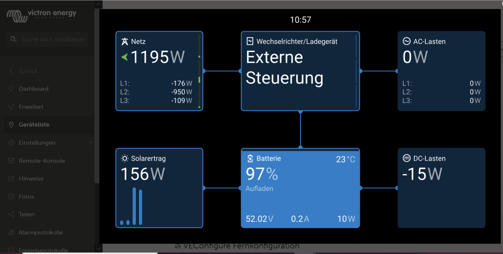
The su is shining and the sould be sommethng about 600W, in any case more then 150W.
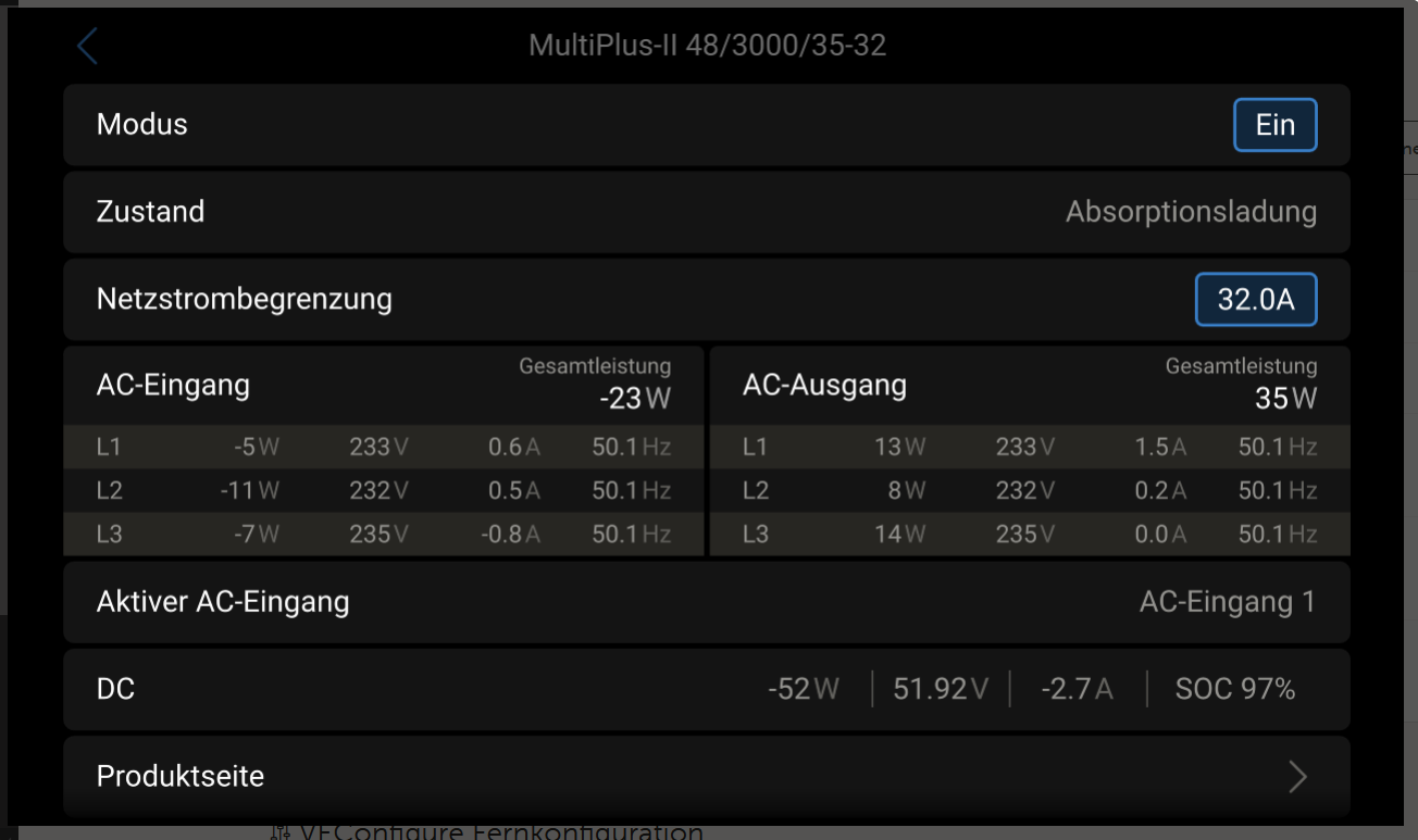
What I wondering is that the in external measurment show the phase power, with some W’s and the multipus show something near 0W
This picture does not make a lot of sense for me unfortunately - You are feeding 1200W to the grid, despite only 156W from solar and the battery being idle:
do You have a second system installed somewhere, that is producing the power?
do You have a second battery, that is used by the MPs, but not shown here?
Are Your loads (e.g. fridge, oven) in the house connected to AC-IN or AC-OUT?
But to comment on Your problem, that You have 156W instead of 600W:
Was the sun shining and really good conditions to reach the maximum of the solar panels?
If yes, then You need to search for the cause. I would check:
The MPPTs (e.g. double click on “Solarertrag”, then You see, what each of the MPPTs produces, maybe only some of them have an issue.
If You find an issue with an MPPT first check the configuration via Victron Connect (bluetooth or via VRM, if Your cerbo is in the VRM portal)
If the MPPT does not have a power limit set, that stops it, You need to check the wiring before the MPPT, probably something is not connected properly.
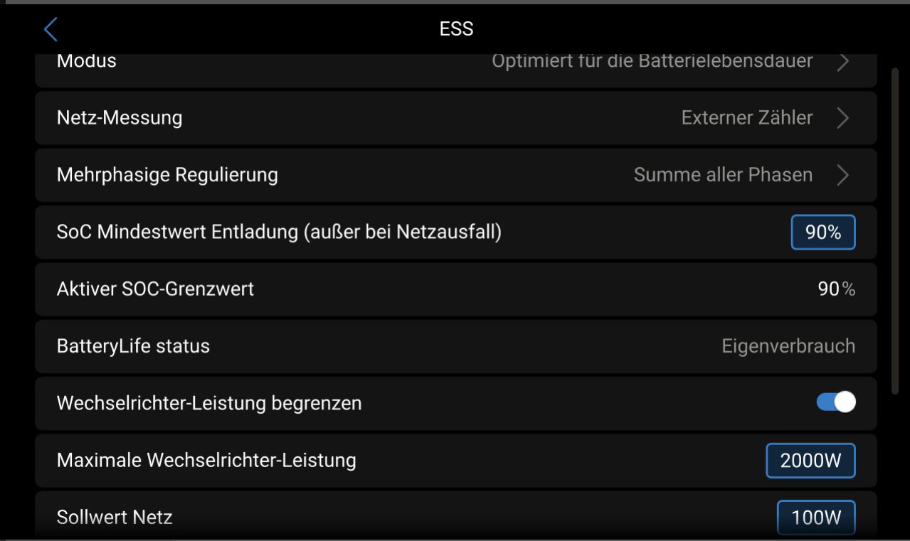
To comment on Your settings:
Why do You have 90% minimum SOC set? That means, Your system will start inverting only above 90% and stop inverting, once it reaches 90%. If You have the system to have power once the grid fails, that would make sense, otherwise not. e.g. my minimum SOC is 1%, because i configured the inverter to stop based on Voltage and not based on SOC. Realistically inverting stops around 3% on my system.
In addition to what @guru_00_00 has said, make use of your multimeter. Measure what your MPPTs are receiving from your panels and what they are outputting. That should tell you where the problem lies.