Hi Mark, I do have an MK3 and it is configured as 3 phase, with the checkbox “Switch as group” and the 3phases configured. The ESS assistants are loaded. the 3 MP’s are daisy chained on the ve-bus.
The behaviour of tripping happens regardless if AC out is activated in the ESS settings or not.
I am with you. I cannot think of anything changing since. I started on a change by exchanging the 3 individual breakers on the AC out to the C characteristic breaker on the photo. With the 3 individual B characteristic breakers they tripped and not the AC IN.
I learned that they had to be C characteristic, that is when I run in the currenting AC IN issue.
The settings look good. But I will double check via VRM
He John,
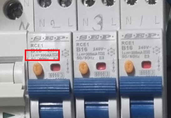
The AC IN breakers do have a test button, so probably also earth leakage detection. If there is potential difference and earth leakage trips on that, then exchanging the breakers has another argument. I think it was @DuivertNL who already made a remark on the quality of the brand installed.
If you mean the most right brown wire on the AC IN side, then I will check/correct that when exchanging the breakers.
The used grid code is Germany. I have always understood that is the one to be used for the Netherlands.
I have read that getting the grid code password is matter of a good google exercise ![]()
Would that be the Grid code setting : AC Neutral path externally joined (not compliant)
Correct
1 Like
The real question is…
Did it work like that ![]()
My system is on german code too from day one, running smooth for almost 3 years, neutrals connected on ac input and neutrals connected on ac output
I believe there now is a grid code for the netherlands
So german gridcode should not be the problem
1 Like
This weekend I am going to exchange the tripping breakers…
Then I can check on the grid code too.
I’ve only just seen this, but the breakers have a test switch, which means they must include residual current detection.
They will almost certainly be tripping due to this (30mA leakage) and not overcurrent.
The reason why they didn’t trip when you were operating in grid parallel is likely because the inverter was not supplying the load entirely, so some of leakage is seen across the grid feed, and some across the inverter supply.
Now you are feeding circuits entirely from ac out 1, and all the leakage current is detected by the RCBO’s on the ac out 1 phases, and it’s enough to make them trip.
Using RCDs and RCBO’s on inverters where it’s not explicitly required…. That will make your life difficult.
With modern electronics, earth leakage is unavoidable, and soon adds up.
1 Like
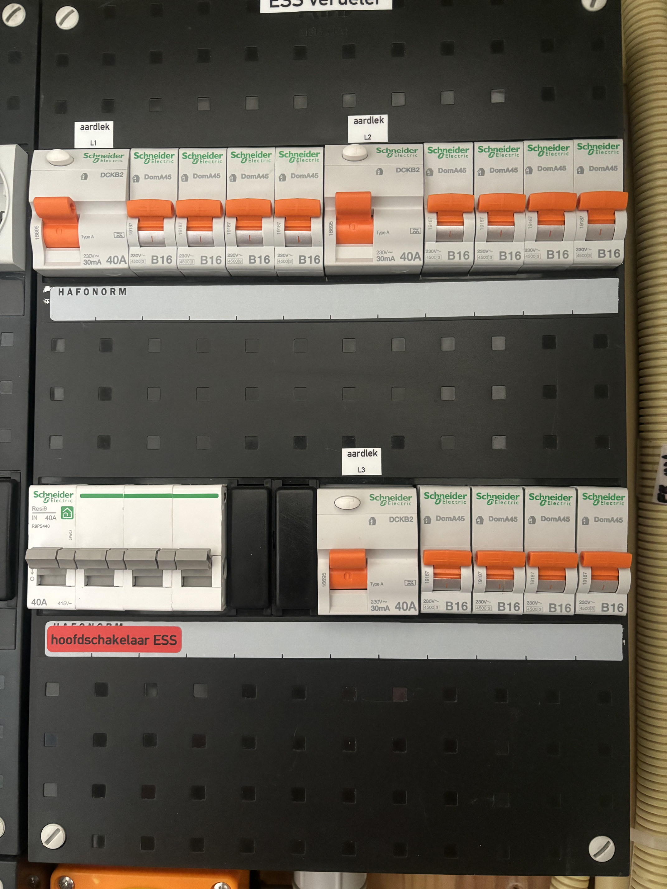
You have NO fuses before the multis but 3 separate FI / LS … as well as residual current circuit breakers.
This does not work … you always need a 4-pole residual current circuit breaker On the AC In AND AC Out … otherwise the 1-pole ones will always trip because you are splitting the neutral conductor …
and as long as you do NOT combine the neutral conductors at the output, nothing happens because the neutral conductor currents are OK. But if you bring them together, the 1-pole ones will trip …
3 Likes
Thats not completly treu, as i already mentioned 3p+n with earth leakage detection 30mA on ac in is mandatory in the NL,
3 separate 1p+n or 1 3p+n with earth leakage 30mA on ac out with combined neutral is both possible and legal in NL, with 1p+n neutral has to be connected on ac input of 1p+n breakers however
My system is setup just like that and running almost 3 years now with no problems, only difference is that i have 3p+n main switch and 3 1p+n breakers with earth leakage 30mA on ac out
So in his system wiring is wrong or the breakers are bad (quality)
You said:
“My system is setup just like that and running almost 3 years now with no problems, only difference is that i have 3p+n with earth leakage 30mA on ac in and out”
that is what i wrote above … with a 3p+n is it no problem … you can combine the N or not …
1 Like
May I ask you to share which type and brand 3p+n devices with earth leakage detection and 30mA you have installed in your setup?
Schneider resi9 B20A 30mA 3p+n, but only on ac in, corrected my previous answer!
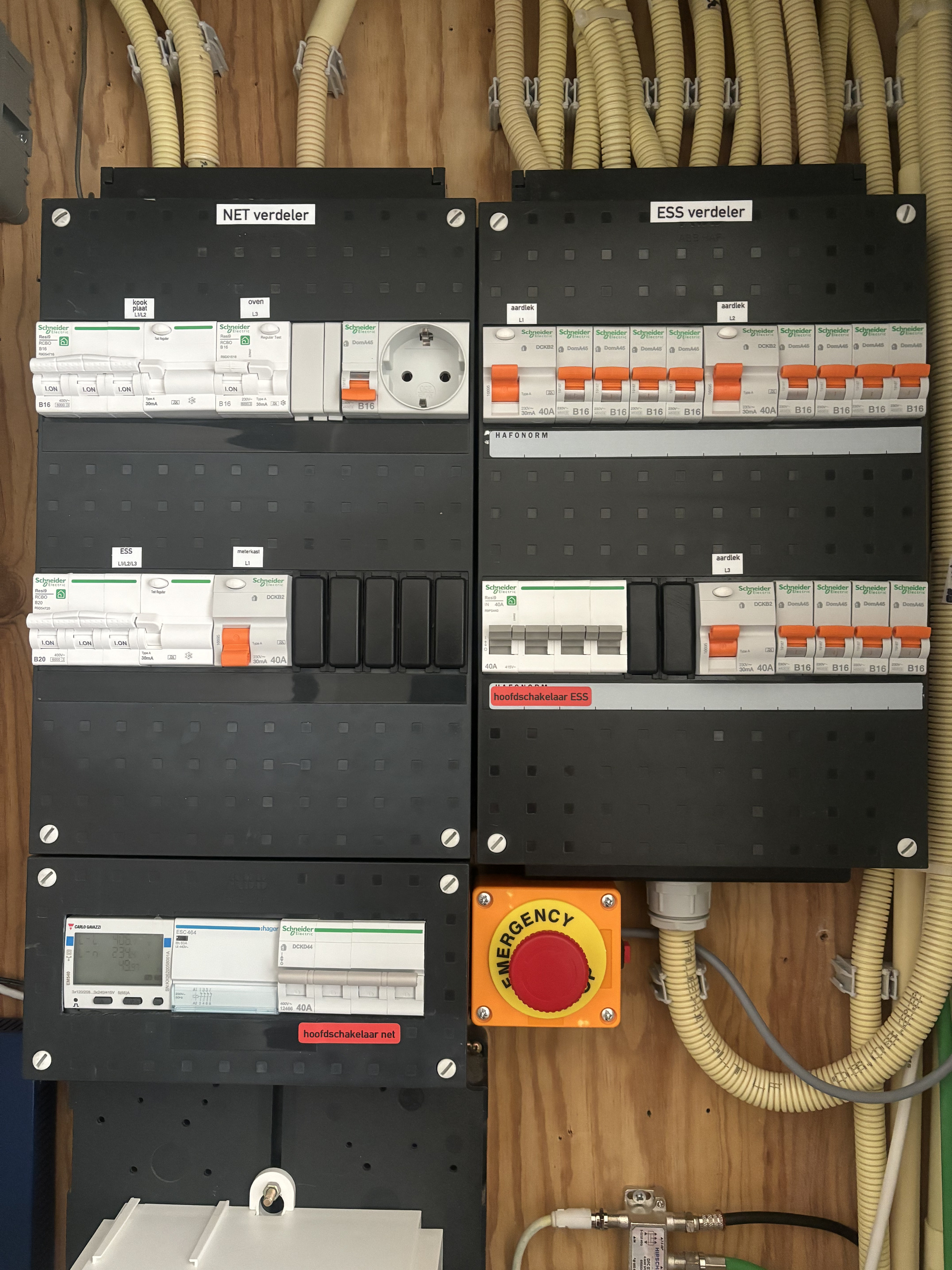
Left side is grid input distributor, (power to ESS system, oven, ceramic cooking)
rightside is ESS distributor, to rest off the house
1 Like
The issue is that you cannot combine the N downstream of the RCD; so on the AC-Out, you can use 1P RCDs provided you keep the N’s separate after them (as you would do in any distribution board), but this is impossible on the AC-In, where the N’s get recombined at the multis.
Hi Christian, What do you mean with " you cannot combine the N downstream of the RCD"?
I can understand that N of AC IN is not to be combined with the N of AC OUT. Is that what your mean?
In my current situation, the AC IN trips when the AC OUT1 is combined without any breaker in between, just the 3 Neutrals of the 3 multis combined to 1, as is depicted by Victron in setting up a 3 phase system.

I like the emergency stop! I would have built that in also if I had known earlier. ![]()