Im sorry but a certified electrician would never use cheap brands like that…
All the wago’s in there are forbidden, only different type of wago’s on holder are allowed, but i just see in your second picture they are temporarily i think, thats ok
If you can make a complet drawing of how its wired, then that could be ruled out as the problem
Hi Steffen, That is exactly what I do not understand either. What is the connection that the AC IN trips when 3 Neutrals are connected on the AC OUT (regardless if they are connected to the installation or connected in WAGO).
A dodgy circuit breaker on the AC IN? The trip happens after approx 30 seconds. When starting up the system, all the relay tests of the system are passed. You can hear the multis 1 by 1 clicking all the relays. And then, like it wants to switch to parallel to the grid, it trips. I do not know if multi switch like that with a power dip or spike as a result.
Therefore, I was triggered also by your suggestion (that I did not fully understand) Did you mean, having the AC outs combined, start up the system without AC IN and then 1 by 1 switch on the AC in?
However, if you go back to your main distribution board with the AC Out cables, this must also be cleanly separated. What have you separated here into normal and emergency supply?
PS … what is WC ? It probably won’t be a water toilet, will it
and again the question about a changeover switch in the house … You don’t have everything running via the multis now, do you?
WC = power outlet, socket. I would not recommend to use it as a toilet ;-).
I have 2 spare sockets installed. 1 on AC In and one on the AC OUT L2. On the AC IN socket, I have the power of the cerbo connected. That breaker does not trip, by the way.
No I have nothing running over the multis. When testing I switch off the main switch (in blue on the left bottom corner on the photo. Now the only things connected to the AC out are the WAGO and ground.
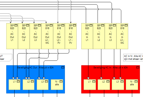
The blue colored wires are L + N from the AC OUT1 of each of the multis.
The green colored wires are the Wires towards the AC IN of each of the multis.
The blue ones are now connected in the WAGO.
The Orange is the Grid from the house towards the AC in
The red is the AC OUT to the house.
In the central kabinet there is a main switch to connect the AC OUT to the house and disconnect the house from the grid.
I had exactly the same problem with tripping a fuse. What the Multiplus II does, is connecting the Vout 1 N to ground. I didn’t configure the 3 phase system as a 3 phase system. Please check if you can temporary can get a MK3 interface to make sure that your system is correctly configured. I think it’s not configured in the right way. It’s probably probably configured wong as a parallel system and you have to reconfigure it as a 3 phase system. Connect the VE-Bus from the cerbo GX to VE-bus connection of multiplus L1, connect the second VE-bus connection of multiplus L1 to the first VE-bus connection on multiplus L2, connect the second VE-bus connection of multiplus L2 to the first VE-bus connection on multiplus L3, connect the second VE-bus connection to the MK3. download the victron software and reconfigure the multiplus devices as a 3 phase system. use VE bus system configurator to configure this as a 3 phase system. Please also check all the other settings and you probably also want to enable ESS. You will noticed that the fuse will not trigger again after you applied the correct configuration.
I’m not an electrician so these are just basic observations from what you wrote and the photo. You keeps saying “neutrals” but I assume you mean neutral as there can only be one neutral. It can branch to many circuits but it’s still the same neutral. I don’t know NL’s electrical system but if it’s like Australia’s neutral and earth are bonded together - if there is a potential difference between earth and neutral a CB with earth leakage detection (RCCB) then they will trip. I don’t love the way the AC in is connected - the brown wire (I assume phase 1) looks like it is too short and has been forced to fit at an angle. Could just be the photo.
This is the sentence on top that I am worried about…
The only thing I am saying is…Make sure that it has the right configuration. I think you can also check this by going to the VRM website and download the remote configuration and look at the settings in your victron software.
There is a grid code made for the neutrals combined on ac in and out. (Yes you will need a password to change it. Not sure if you know or have it. No we won’t post publicly on the forum).
The grid code is non compliant. Possibly you can test the wiring/set up with it and switch back to your officially accepted grid code for your region if you eliminate what it is.