Hello. I am researching if I can upgrade from my 12v leadacid bank to lithium on my sailboat.
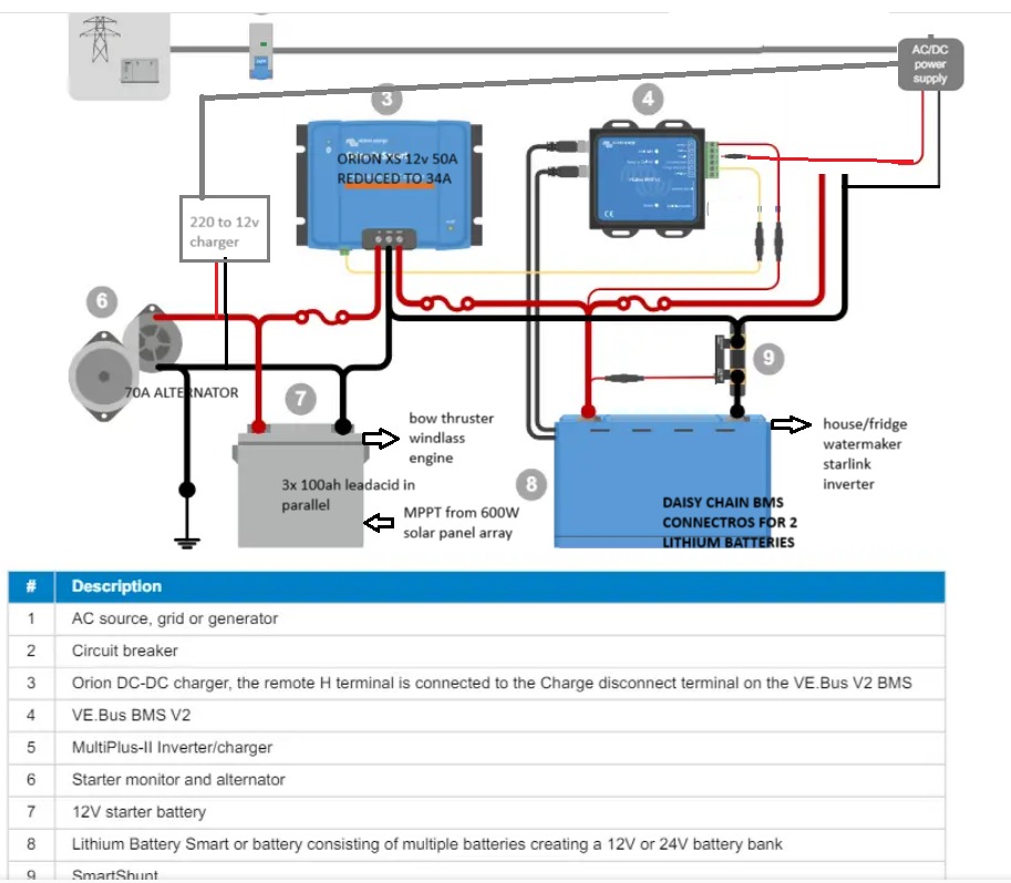
The problem is I am very limited to the parts that I can buy as I am on a remote island in the pacific. I came up with the installation in the image and would love to hear if I made any mistakes or could do things better than this installation.
I can add simple analog voltage meters to monitor the two battery banks as these are available to me (the smartshunt in the image is not available to me).
The system is sound from a brief review, a couple of comments.
How are you going to protect the battery from over discharge, ideally you should have a (Smart) Battery Protect on the loads from the lithium battery controlled from the ATD terminal on the BMS. However, the inverter can not be controlled directly by a battery protect (details in the battery protect manual).
Can you get the BMV 712 (or a BMV 702 possibly with a Bluetooth dongle) rather than the SmartShunt. I would not want to monitor the lithium batteries just by voltmeter, really would want to use a shunt based system for monitoring SOC, but agree not absolutely necessary.
Do you have a Victron inverter that you need to control by the VE Bus cable. If not then the small BMS if available would be cheaper and more suited to the small install.
Thanks! Great tips.
I protect my system now by constantly looking at my voltmeter 
I will look for the batteryprotect and the bmv712 but they’re probably not here.
What smaller bms are you thinking of?
I may be able to source a lynx ng smart bms in stead of the bms V2, but that is still uncertain and I think that’s a bigger, not smaller solution.
My invertor is an old 500w mastervolt, so no ve.bus or anything smart there.
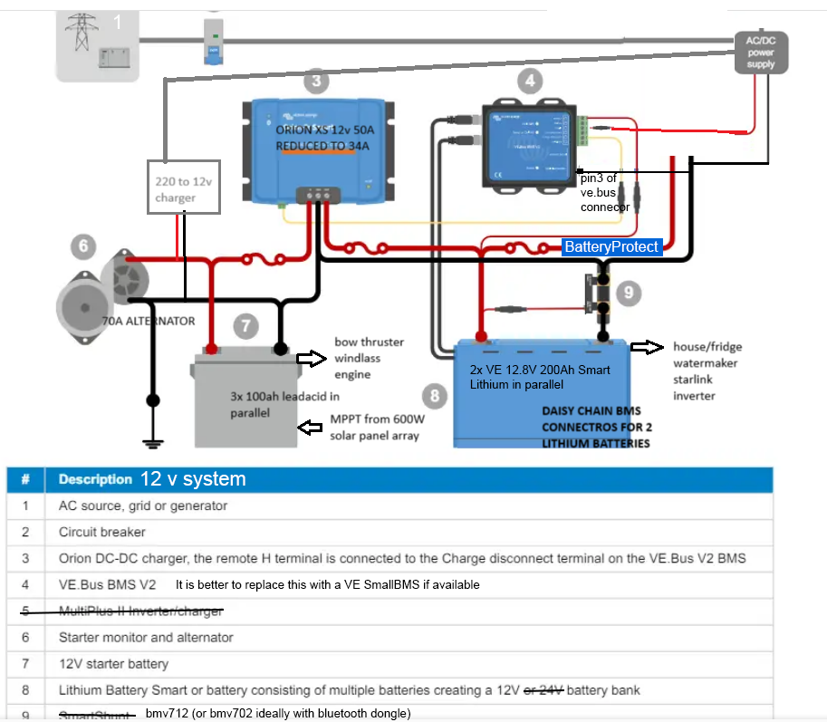
Small BMS link below. The VE Bus BMS mk2 has more features than you need so the Small BMS will suit and be cheaper if you can get it.
Small BMS
Also, the VE Bus BMS mk2 does not have a negative power connection, I forgot this earlier. It gets negative power from the Cat 5 VE Bus cable, there is a workaround on the site. The Small BMS does not have this issue.
Powering VE Bus BMS mk2 without Multiplus
I have the Lynx NG nice bit of kit but expensive for a small system. It has a continuous 0.3A power draw to consider. It comes with inbuilt battery monitor and contactor so is more complete.
Be aware, Victron are changing from Lithium Smart batteries to Lithium NG batteries, NG batteries need an NG BMS, older batteries without NG need a BMS without NG, they are not compatible.
1 Like
Thanks a lot! (again). I incorporated everything in my design and will look for availability of the products. Good to know that I at least will be able to get everything to work with what’s here.
PS: The MPPT in the image is a Victron SmartSolar MPPT 150/85-MC4 VE.can (12V) to charge from solar. I may be able to connect the BMS to this using the VE.can connection in order to get the negative connected, but I am not sure that is the same connector, or if it will work, or it may could cause harm.
Here’s my new design for anyone reading along.
Do not use the VE Can socket for power, VE Can only uses signal wires, there are no power wires in it.
1 Like
Thanks again.
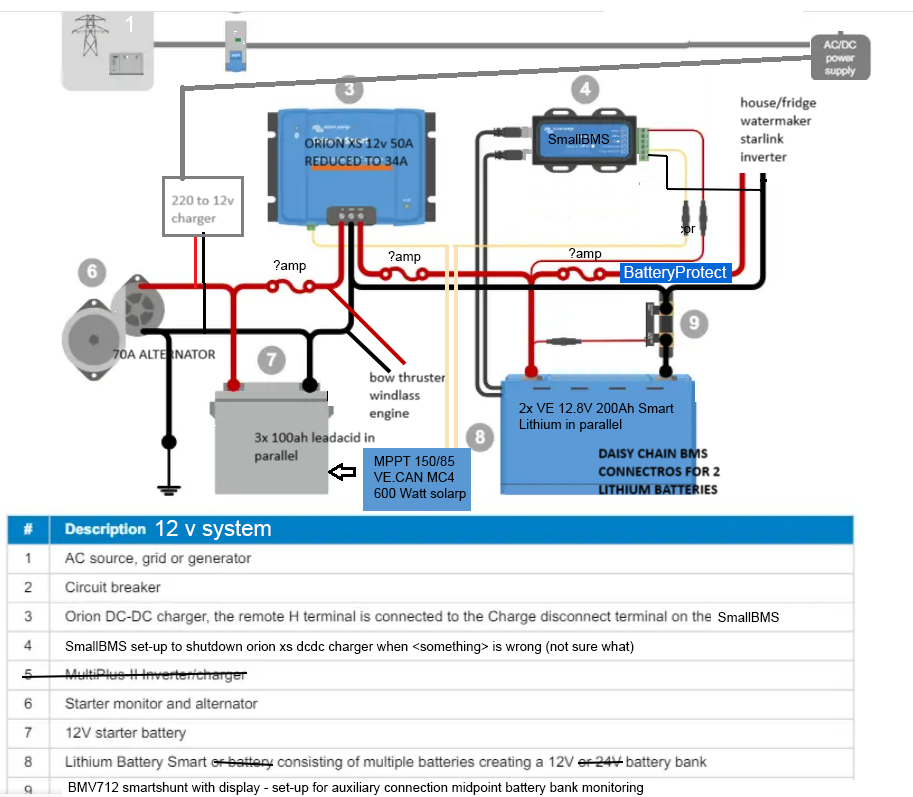
I was able to source a SmallBMS, therefore the missing ground on the BUS BMS v2 is no longer a problem.
Below the new setup. All comments and tips are still welcome! Especially in regards to the wires and fuses I should get and how the system should shut down the orion xs when the starter battery is on low voltage.
One possible way to shut off the orion xs may be to use the relay on the mppt when it detects low voltage on the starter leadacid battery like this:
But I’m unsure if this installation will work. Any recommendations or insights if this is any good are mostly welcome!
The ATC charge wire from the BMS has got to from the BMS to the Orion as that is charging the lithium battery. You could also shut down the MPPT if required to avoid over charging the starter battery, but that is not strictly necessary. If you do want to shut them both down then split the ATC into 2 wires (Y connection) and one goes to the MPPT and one to the Orion XS so that it shuts them both off. How you have shown it will not stop the Orion XS charging.
The Orion XS has a software function to stop it discharging the starter battery, a combination of a lockout function and the engine charging detection, so you can set it to absolutely stop charging if the starter battery is below say 13.3V which means that the starter battery has to be charging to function. This setting also means that if you only have a low level of solar, which starts the Orion charging, then the Orion will reduce the charge current to maintain the starter battery at 13.2V and match the available solar power going to the lithium battery.
The Battery Protect needs a fused small gauge negative wire.
The hard work starts now, download each product manual from the VictronEnergy website. Each manual will give example wiring schematics, recommended wiring gauge and fuse values. After you have done your reading then update your diagram for a final cross check. I am afraid I am not going to do the design work, this is not the ethos of the community.
1 Like
Thanks once more. I wasn’t aware the orion could stop on low voltage of the starter battery the way you describe. I thought I needed to shut it down remote. Thats why I thought I’d use the mppt relay for that while at the same time I use the BMS to prevent overcharging.
It sounds like I got a bit too creative.
Great tip on the battery protect snd manuals. I guess I’ll keep reading.  Although I get the feeling some features won’t be clear to me until I have the devices in my hand and in the victron app.
Just keep coming back with questions or if you need clarification and you will get help and guidance.
2 Likes
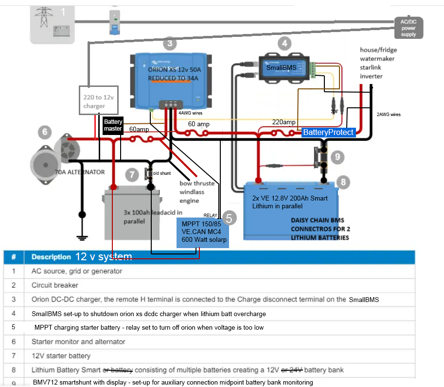
Thanks. I rewired the orion. Now I use the MPPT relay to shut it down if the starter-battery is low on voltage and I use the BMS to turn it off when the lithiums overcharge.
The question I can’t seem to answer is how the ‘remote on/off’ on the Orion works when you use both L and H. Does the Orion turn off if only one (L or H) is switched off or will it only turn off if both (H and L) are off?
In the manual I can’t find the setting for this. Maybe I must wait for the Orion to arrive or are there more detailed manuals?
I have no idea what it will do if one terminal says on and one says off, I have had a search and can find no answer.
Why not create a new question asking what happens if you use both the L and H terminals, does it need just one to be off or both to be off to turn the charger off. Someone may know the answer to that question who is not checking on this thread.
I saw people looking for the same answer but no solution yet.
I want the charger to stop if either H or L is switched off, or both.
For now I’ll have to see if there is a different way to do it or, if that fails, drop one of these nice safety features.
You have lead acid batteries in parallel with lithium batteries. This is NOT good.
They operate differently in charge, discharge and their terminal/charge voltages.
One or both will be destroyed in this system, as drawn.
If you wish to use TWO batteries then you need two systems. The only common point could be a common ground wire, even that could be bad, especially if the battery chargers switch the ground leg for PWM or MPPT control.
@ira251166 please explain where there are batteries in parallel. Please explain why the scheme shown which is a completely standard scheme used countless times is not acceptable. Please explain why the DC to DC charger does not separate the batteries. The DC to DC charger is being used per the Victron manuals.
@Martijn1 Ignore this comment.
My bad, I saw the thin red line going across the terminals as a connection. It was obviously NOT a connection.
I was looking at the line that goes to the left of the 60 Amp fuse, across the bow thruster windlass engine connection line and to the other 60 Amp fuse.
If this is just a label or similar then please ignore my comment, if it’s a low amperage DC cable, (being red), then it will need to go. It would be better if all power cables ‘jumped’ over other cables where no connection was intended, OR a dot was placed at connections. It might even help if non power lines on the sketch were not red/black.
That is the small gauge wire for the battery master which is a trickle charger.
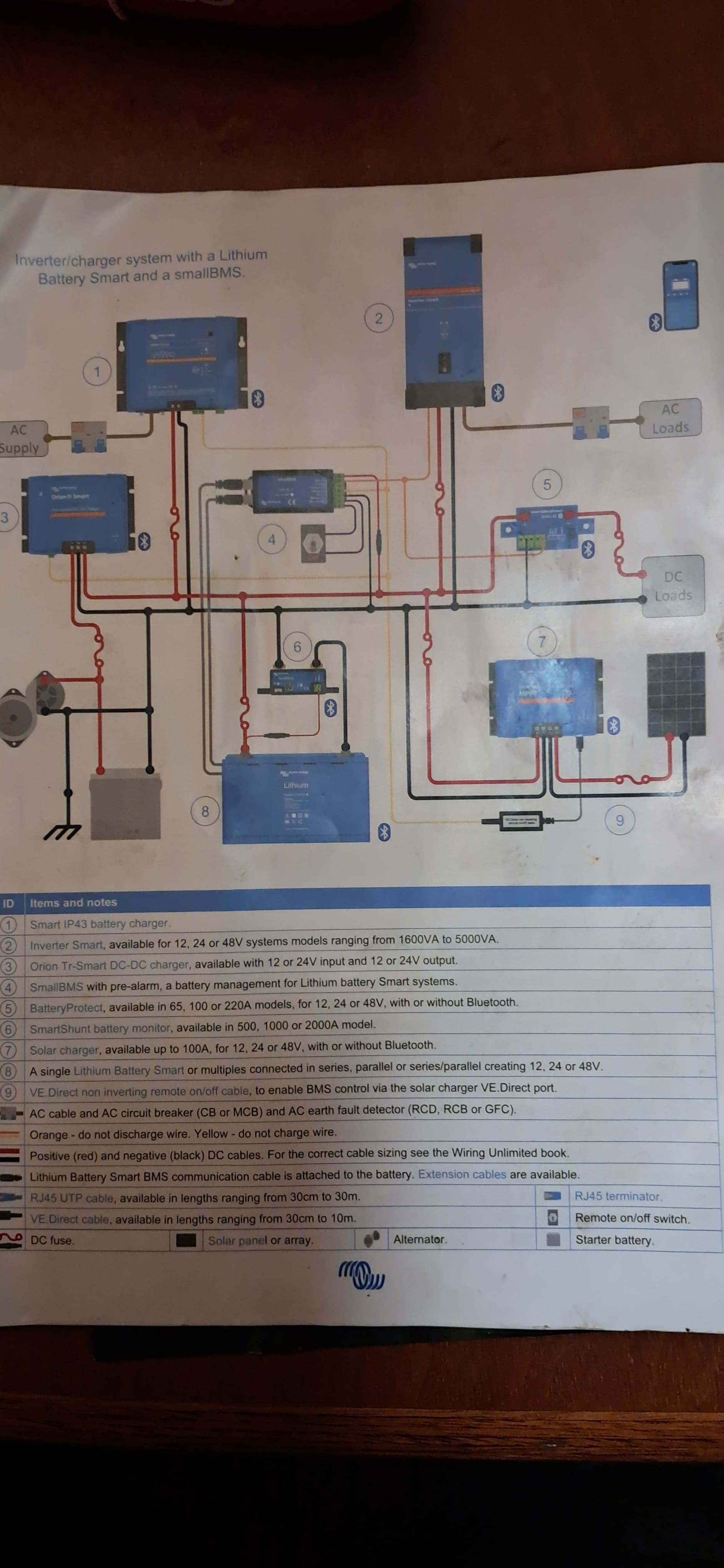
I no longer plan implementing this design. I found a book with official designs I trust more than my own.