Smart Shunt not resetting to 100%

If you have nothing connected to the load outputs then you turn the load output to off.

You have 6 MPPTs, are these all connected to the Cerbo GX by VE Direct cables or VE Direct to USB cables. Are the MPPTs connected by a Bluetooth VE Smart Network.

@pwfarnell Does this seem odd to you? I’d have expected at this point they go into float, or the battery discharge would retrigger the charging cycle, Bulk->Absorption->Float
Something just doesn’t seem right at all here.

@Jseb Who was the installer?

Why do so many ‘installers’ advised about on this forum seem to go missing / stop responding.

I’m busy for a while now, so hope you can get this resolved.

Yes, something is very odd here, the MPPTs should go into absorption for a period and hold the voltage and continue charging until the tail current went down steadily. I do not understand it, but now we get more details with so many chargers, if the installer set up a VE Smart Network AND added VE Direct cables then this can be bad news as parallel comms system can give rise to erratic and unpredictable results, which is why I asked about this.

1 Like

So it looks like the mppts are on a smart network from a prior owner (screenshot).
Mppt 1-3 (100/30) are going into the Cerbo with VE direct cables. Mppt 4-6 (100/20) go into a 3 USB adapter that exits as a single HDMI going into the Cerbo.

HDMI ???

The HDMI port is only for display connections. AFAIK the CerboGX HDMI has no data transmission capability over HDMI.

  1. Hopefully you mean they are going onto a common single usb port because as @anon39974850 says, the HDMI is only for the touchscreen. If it is HDMI then get a USB hub.
  2. Is the SmartShunt connected to the Crrbo GX, it needs to be, again into the usb hub or a usb port.
  3. Take down the VE Smart Network.
  4. Enable DVCC, enable SVS and SCS, sharing voltage and current sense from the SmartShunt.
  5. The Cerbo manual has info on connecting devices snd DVCC.
  6. If you had mentioned your system detail in the first post I would have guessed the problem straight away as I did once you described it, I thought you had 1 MPPT.
  7. No wonder the installer has gone quiet, thry hsve left a mess behind.
1 Like

Sorry - correction. Mppt 1-3 are in my starboard hull with the Cerbo and mppt 4-6 are in port, so having to go back and forth. It looks like it’s 3 USB in to 1 USB out that goes into the BMS can USB port with a ve bus to USB adapter.

I have the shunt set to a charged voltage of 13.8v. would the mppt absorption need to be changed to this? Or keep at 14.2v?

Keep the MPPTs at 14.2, then there is more headroom for the shunt to reach synchronisation, even if it is a bit early.

Just making sure the DVCC is correct. I did everything recommended but today (full sun) the system did the same thing; voltage rising, hits around 13.8-14v, then throttles down the solar. Mppts are at a constant 14.2v showing absorption , but -15-20A current is still being drawn. There’s definitely enough sun to be producing 1000w or so, but only putting in 600ish.


Your SmartShunt needs to be visible on the Cerbo and you need to have selected this as the battery monitor on the settings > system setup > battery monitor menu and it should then forward the battery voltage and current to the MPPTs with your DVCC settings.


This has always been set to the smart shunt.
Shunt is set as battery monitor in Victron connect (not DC meter).

Everything looks right.

The MPPT should be able to continue supplying the loads. Some other things to try but clutching at straws here.

  1. When the SmartShunt is at 14.2V and -20A, use a multimeter to check the voltage at the battery terminals on the MPPT and the battery to see if they are the same, just in case there is a bad voltage drop problem.
  2. Does you have a multimeter with a DC clamp ammeter to confirm the -20A reading, perhaps this is wrong and it is really setting down at 0Amp and is misreading for some reason.
  3. When the SmartShunt is at 14.2V and -20A, have a look at each of the MPPTs on VictronConnect or the GX device and see what they are producing.
  4. You can do a zero current calibration, details in the manual.
  5. No idea if all the VE direct and USB comms could be causing an issue, you could always try disconnecting all the MPPTs and only connecting the SmartShunt.
  6. You could try and start a new topic, “why do my MPPTs behave weirdly”.

Got back to the boat today after an outing and the system reached 14.2v and current dropped as per usual. I checked the voltage at the mppt battery terminals and they were more or less the same as the readings from Victron Connect (+/- 0.02-4V). The current readings from the mppts were also congruent. Battery voltage and current were also congruent - showing about 20


amp draw.
The funny thing is when I was double checking readings mppt 2 & 3 went into float, but others were still in absorption. Checked voltage again and mppt 2 & 3 were reading 0.2volts less than was reported on Connect

I notice an Orion 30A unit listed in the screenshot running in bulk. Where is this charging from and to. It this possibly a source of current flow through the shunt that could be affecting things.

I am going to stay off your new thread so it does not look like it is in hand like this thread and hope others will post to get some new ideas.

There are 2 isolated Orion 12/12 30s for charging engine batteries from the alternators. Settings as follows. But one of the last communications I had with the installer was regarding if these could be culprit, to which they stated these wouldn’t draw away from the house batteries at all. I have Balmar alternators with a center fielder that handle charging the house lithium from the alternators.
The only other equipment in the system is a Multiplus inverter/charger, but that’s generally off unless we need to run an AC appliance or hook up to shore power.


I know that I have said this before, but the new information really does help understand and I believe that this may be the issue.

The alternators charge the house batteries, hence the house batteries charge the engine batteries because the alternator output is connected to the house batteries. The only way that this could be stopped is if you have the alternator output going to a switching device such as an ArgoFET and the Orions are connected to one output and the lithium house bank to another. I find this hard to believe, so I am going to write this on the basis that the Orions are essentially connected to the house bank.

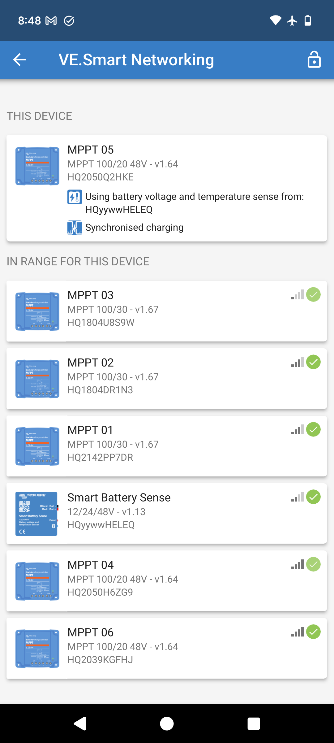
Clearly in this image I am going to assume that the engine is not running but the one Orion shown is in bulk charge and your batteries are starting to float. So the boat builders assertion that the Orions could not draw from the house batteries is wrong in my view, because the screenshot clearly shows otherwise.

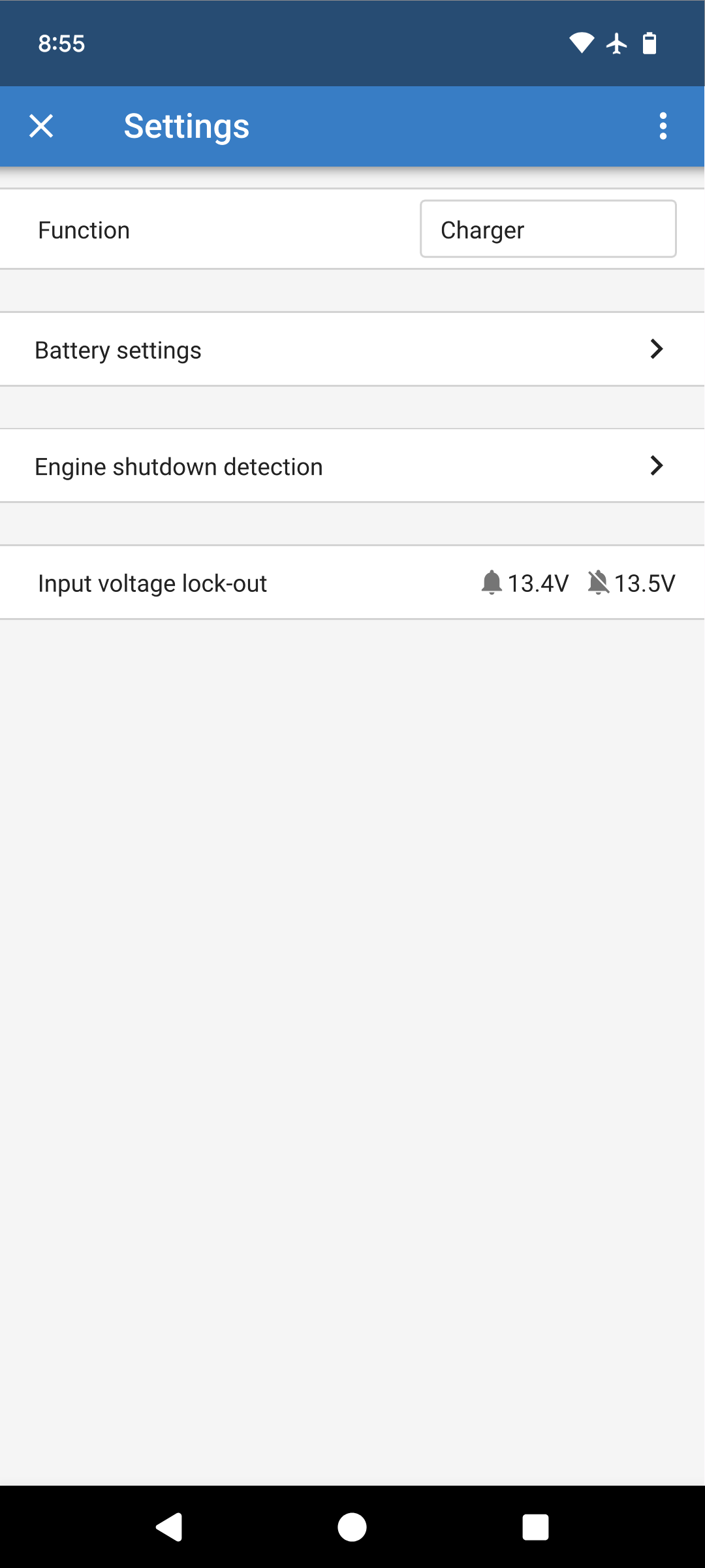
The Orions are set up with voltage lockout and engine shutdown detection

image

Voltage lockout means that charging will not start until the house batteries are above 13.5V and when they fall below 13.4V they stop charging, these settings over ride the engine lock out.

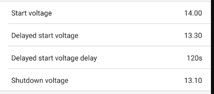
The engine shutdown detection means that once 13.5V has been charging can start. If the voltage is above 14.0V it starts immediately, otherwise it starts after 120 seconds. These voltages are reached by solar charging so the Orions will charge the engine batteries from solar, which is not a bad thing if you are going on longer periods without running the engines as it keeps up with the parasitic loads on the engine batteries. The Orion settings are safe because they will stop the engine batteries discharging the lithium batteries as stopping at 13.4V will be around 90-95% SOC.

What is probably happening with your system is that the Orions start to charge the engine batteries just as the lithium batteries are almost full, the voltage ramps up very rapidly towards the end and the batteries as full because it is a low charge rate compared to the battery capacity.

Prior to charging you have a current load of around 20A, solar generates 60A so you charge at 40A. At the end of solar charging, the Orions start to charge and lets assume that they take 30A each, consume all that the the solar is producing, so you then go back to the case that once these start charging, your consumption exceeds the production so your batteries start discharging. As the batteries start discharging before the SmartShunt has synchronised it never will. I was convinced early on that you had a load kicking in at this time and we went around the load output, here it is.

Things to think about.

In terms of your shunt and synchronisation, it may be best to reduce the charged voltage to 13.7V or 13.8V and a tail current of 4% and a charged detection time of only 1 minute so that it synchronises much sooner and works with your set up and gets a reset to 100% to avoid long term drift. The risk is an occasional reset to 100% too early.

Changes could be made to the Orions to stop them charging as much or changing from engine shutdown detection to switched from the ignition wire so they definitely only come on with the engine(s). Using the solar to keep the engine batteries topped up is usually a good thing.

You will need to look at your data to see if they worked better with the VE Smart Network or not, was synchronised operation better.

Do a trial, turn the Orions off in victronConnect battery settings page for a day and see what happens.

On shorepower and possibly with the alternator(s) with a higher charging current the 13.5VOrion start up voltage will be reached earlier in the recharge while to SOC is lower. The current the Orions demand will be covered by the higher power charger and the lithium batteries will continue to charge. As the Orions will have longer to charge the starter batteries by time the lithium batteries get to 100%, the current the Orions demand will be reducing.

The other thing is that as the lithium batteries start discharging before they get to absorption voltage they may not get a lot of balancing.