I’m looking for input from the community and Victron engineers regarding a persistent oscillation issue we’ve been troubleshooting.
System Overview
Inverters: 2× Quattro 48/10000 units configured for split-phase (L1/L2)
Battery: 6× EG4 48 V 100 Ah LiFePO₄ (LL-S, total ~30 kWh)
Solar: 4.98 kW DC (12 × 415 W panels)
MPPT: Victron SmartSolar MPPT 250/100
Control: Cerbo GX running Venus OS 3.65 / 3.66 / 3.70 Beta — all tested with identical results
ESS Mode: Enabled, “Optimized with BatteryLife”
Energy Meter: Carlo Gavazzi EM540DINAV23XS1X (2-phase mode, 150 A:5 A CTs on grid feed) — Victron software currently appears to force the system into 3-phase mode due to configuration handling; see related post for details.
Grid: Utility on AC-in 1
Generator: Generac 24 kW NG on AC-in 2
Issue Description
Under ESS operation, the system develops rapid oscillations of ±80–100 A DC and corresponding swings on AC-in and AC-out when inverter loads exceed roughly 4 kW total.
Symptoms include:
Audible relay “clicking” from both Quattros during oscillations.
Grid and inverter current readings fluctuate heavily, visible on both EM540 and Victron VRM.
AC1 voltage and current show strong modulation in sync with VE.Bus DC power.
When inverter limit is capped at 4 kW, system stabilizes and runs without oscillating.
During off-grid operation (AC1 and AC2 disconnected), system runs normally — no oscillations at any load, up to 20 kW.
Testing & Observations
The EM540 updates every 100 ms; wiring and phase assignments verified.
ESS roles and energy meter role = “Grid.”
No AC-coupled PV.
Both Quattros’ firmware are the latest available VE.Bus versions.
Oscillation occurs whether “Optimized” or “Not Optimized (No BatteryLife)” ESS state.
Oscillations do not occur when ESS is set to “Keep Batteries Charged.”
Frequency and voltage remain stable at grid connection.
Behavior is consistent across all tested Venus OS versions: 3.65, 3.66, and 3.70 Beta.
Data
We’ve logged data with the VE.Bus high-res logger and EM540 CSV output, showing synchronous oscillations between AC-in, AC-out, and DC bus current. A detailed PDF and CSV plots are available if needed.
Request for Input
Has anyone seen oscillations like this with dual Quattros in split-phase ESS mode?
Could this relate to current feedback timing between the EM540 and VE.Bus control loop? (Though it also occurs with just the Victron Quattros measuring current.)
Any firmware parameters or beta builds that improve grid feedback stability?
Would adding a “rate limiter” on ESS current control (Node-RED or otherwise) stabilize feedback?
We’ve already been in touch with our dealer, but they aren’t ESS certified, so I’m hoping for guidance from Victron engineering or experienced users.
Would appreciate any suggestions or insights from others who have experienced similar behavior in ESS systems.
So the oscillations have been happening long before installing the EM540. It occurred just with using the Quattros to measure current usage. The only reason I got the 540 is the dealer/tech support said that Quattro couldn’t update fast enough so needed and external meter. The 540 updates at 100ms which is pretty cool to watch on ekrano GX update so fast.
The 540 is setup correctly. CT with correct directional current and each CT reports amperage for the correct phase (L1 and L2). Certain. Checked it numerous times. 540 is programmed with 30 for the CT ratio. Did take me a while to figure that one out. The software for the 540 does it at 150 per 5, but if you program through the display screen it is confusing. Take 150/5 and you get 30 for the CT ratio. The amps report perfectly to a clamp applied to the cables. Also the amps are right with what is shown by the Quattros with or without the meter engaged.
Does not matter multiphase or individual phase.
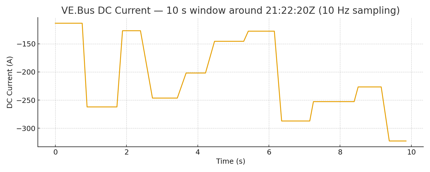
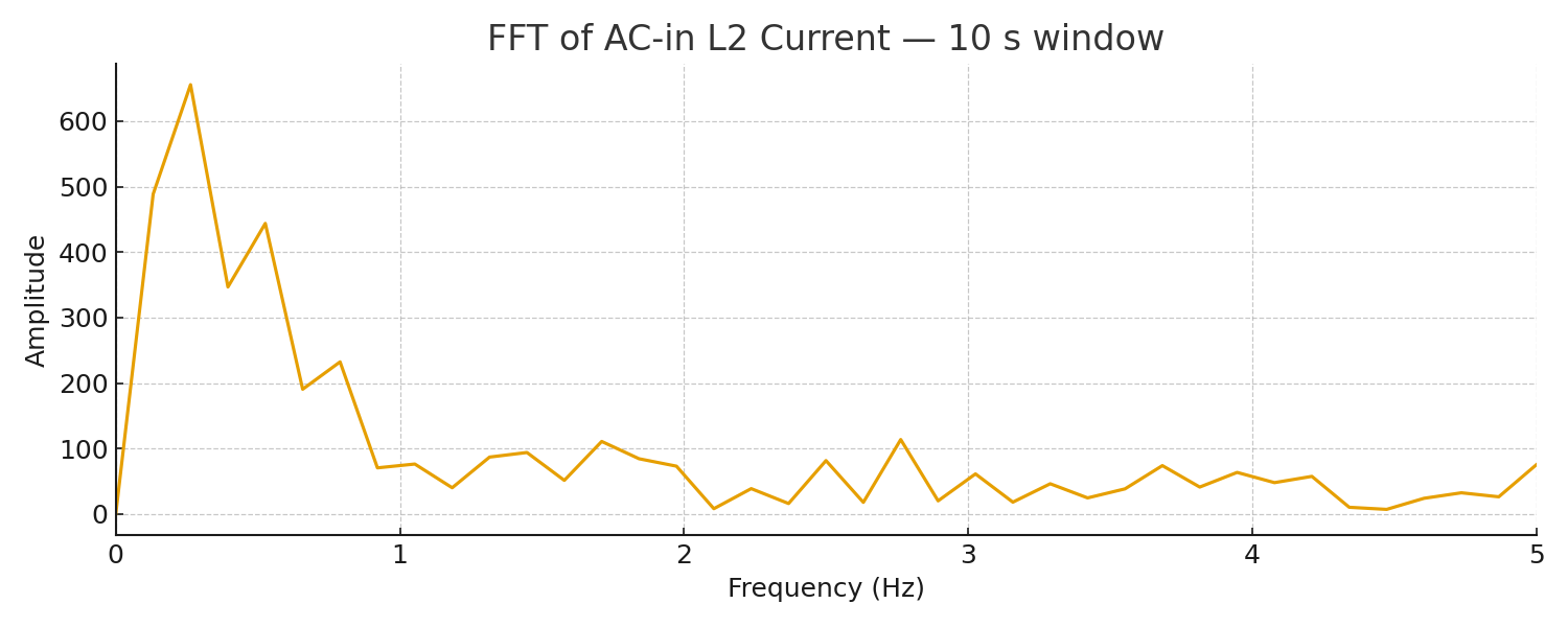
Oscillations are around 1-3Hz.
Using “other” grid code with LOM for the utility input. This is a US installation.
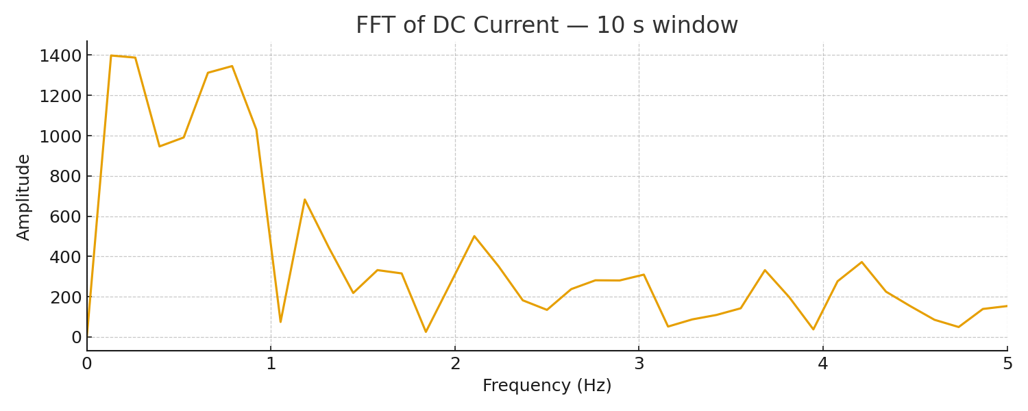
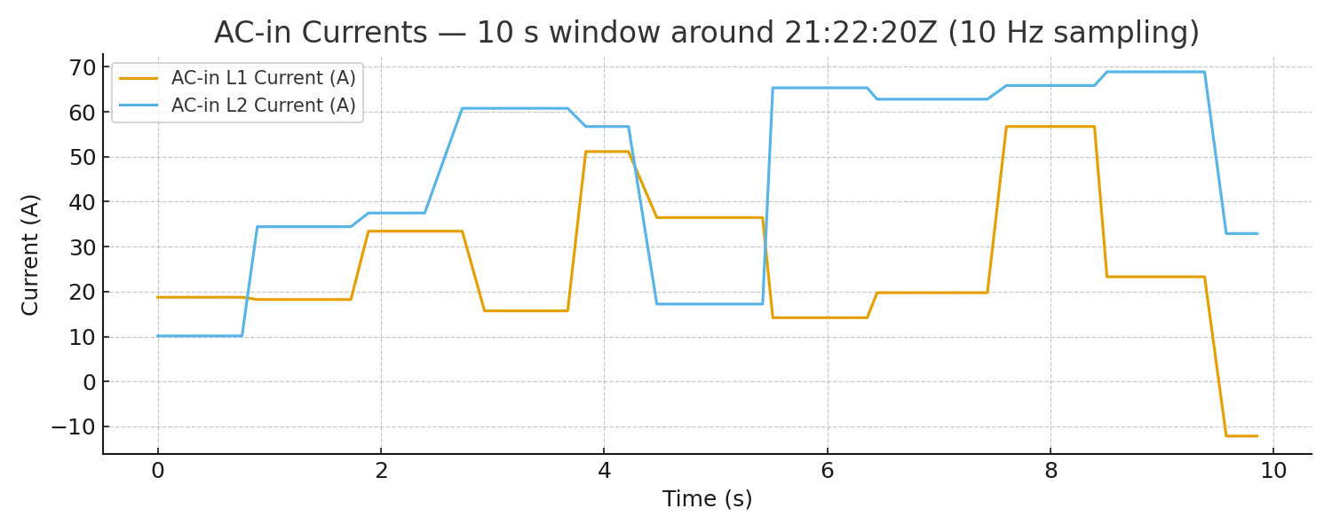
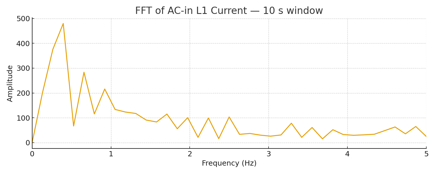
Oscillation frequency confirmation:
Attached are 10-second plots at the onset (21:22:20Z). AC-in and DC currents show periodic swings roughly once per second, with dominant FFT energy below ~2 Hz. This supports a VE.Bus ESS control-loop oscillation while grid-connected. I can share a longer clip or higher-rate segment if helpful.
That’s highly unusual.
I have split-phase 5k Quattros and an EM540 with 200:5A CTs (ratio 40) and have been running ESS successfully for almost two years on Grid Code Other (USA).
Describe the path from the utility transformer to your Quattros. Is there a really long run with potentially higher than normal impedance?
Do you have any unusual highly reactive loads in the house?
I do not understand the nature of the 1-3 Hz oscillations, especially since the EM540 has a superior update rate.
I’m an engineer, and appreciate the FFT results.
To answer your original question about slowing it down, the only way I know to do that is with your own ESS Mode 3 implementation.
I am currently running my own Mode 3 right now, if you are interested I can discuss it, but it is highly specific to my needs here.
It’s probably better to get a fundamental understanding of the root cause of the oscillation, whether that is high impedance or installation error.
Here is a video that shows it with the EM540. The oscillations are the same with the EM540. Skip to the end of the video to see the oscillations. The dealer asked for video of the system. Also not I used the EV charger to put a bigger load on to the system. But this will happen even without the EV car charger. IMG_0021_1
I thought about doing my own ESS Mode 3, but shouldn’t have to as this is straight forward ESS stuff.
The utility comes in to a meter. There is <100 feet run from the meter to a disconnect box. From the disconnect switch < 10 feet to the Quattros. 4-0 Aluminum wire from meter up to the disconnects. 3-0 copper after that for everything else. Utility service is 200amp and all wiring is compliant with 200amp, but we never use more than 100amps so the Quattros are fine at 100 amp limitation.
The only warnings during oscillations is overload for L1 and L2.
As far as reactive loads. It is a standard house. 2 AC units with std compressor. 2 split AC units that use ac to dc inverters. A few computer servers. pool pump. The rest is typical refrigerator and household lights. I get the oscillations with or without the EV car charger.
I personally think something is wrong with one of the Quattros sensing and it just fails under increasing load. I haven’t been able to prove anything wrong with the Quattros though. The only unusual indication I get is low battery voltage warning 2-3 times a day for 20 seconds. Using data analysis by OpenAI there is no low voltage. The VE.Bus is reporting a low voltage when there is a rapid change battery voltage. Looking at ½ volt change in milliseconds. I think this normal as load changes and battery management adjusts. The fact that VE.bus thinks it is not normal may be something behind the oscillations problem.
OK, scary video at the end!
I’m currently at a loss to explain what you are seeing. It should be a straightforward ESS implementation.
Nothing unusual about any of that.
How far is it from the utility transformer on the pole (or from a green box on the ground) to the meter?
You’ve got 30 kWh (600 Ah) of battery, which should be enough according the manual.
You’ve got what looks like a single 4/0 AWG battery cable for each Quattro (107 mm^2 equivalent).
Manual recommends 2x 50 mm^2 (1/0 AWG equivalent), I think you are ok there.
The low battery voltage is probably real, you just don’t have a way to measure fast enough.
We need to determine what relays are clicking during the oscillation.
I haven’t a clue what the clicking is. The dealer wasn’t helpful and said that was “normal”. I did do deep dive into the low voltage warnings with the assistance of chatgpt. We built all kinds of red-node diagnostic collections. Here is the report from that.
Analysis of system logs from the Cerbo GX indicates multiple VE.Bus “Low Battery” warnings occurred overnight.
These events were investigated for voltage stability, current transients, and load behavior.
Repeated VE.Bus “Low Battery” warnings lasting ≈ 20 s each
Events occur in early-morning hours (01 :30 – 09 :00 local) when PV generation is minimal
No warnings during daytime or active solar generation
Battery SOC and DC voltages remain normal (> 52.6 V)
Suggests VE.Bus sense-point transient dips, not true pack-level low voltage
Event Diagnostics
Five representative VE.Bus low-battery events were analyzed using ±5 minute windows surrounding each warning time.
Five ±5 min windows (UTC-adjusted)
Plots include VE.Bus DC V, Battery V, v_drop, AC In/Out Power, dv/dt (V/s), and alarm markers
Summary table lists min V, max |dv/dt|, and max AC In (kW) per event
Findings
Analysis of voltage, dv/dt, and AC power correlations confirms that observed warnings are transient sense-point dips rather than true low-battery conditions.
VE.Bus DC V stable ≈ 52.7 – 53.0 V during alarms
dv/dt spikes 0.14 – 0.48 V/s align with alarms
AC In power peaks ≈ 7 kW during events, consistent with transfer/assist transitions
v_drop small (≤ 0.5 V) → minor bus impedance drop
Likely cause: transient VE.Bus DC measurement dips when the inverter transitions from grid support to inverter assist in early morning as PV starts ramping up
Not indicative of low battery or SOC
Event Summary Table
| Local Time | UTC Time | Min VE.Bus DC V | Max |dv/dt| (V/s) | Max AC In (kW) |
|-------------|-----------|------------------|-------------------|----------------|
| 01:37:29 | 05:37:29 UTC | 53.04 | 0.14 | 7.10 |
| 03:08:15 | 07:08:15 UTC | 52.72 | 0.42 | 7.10 |
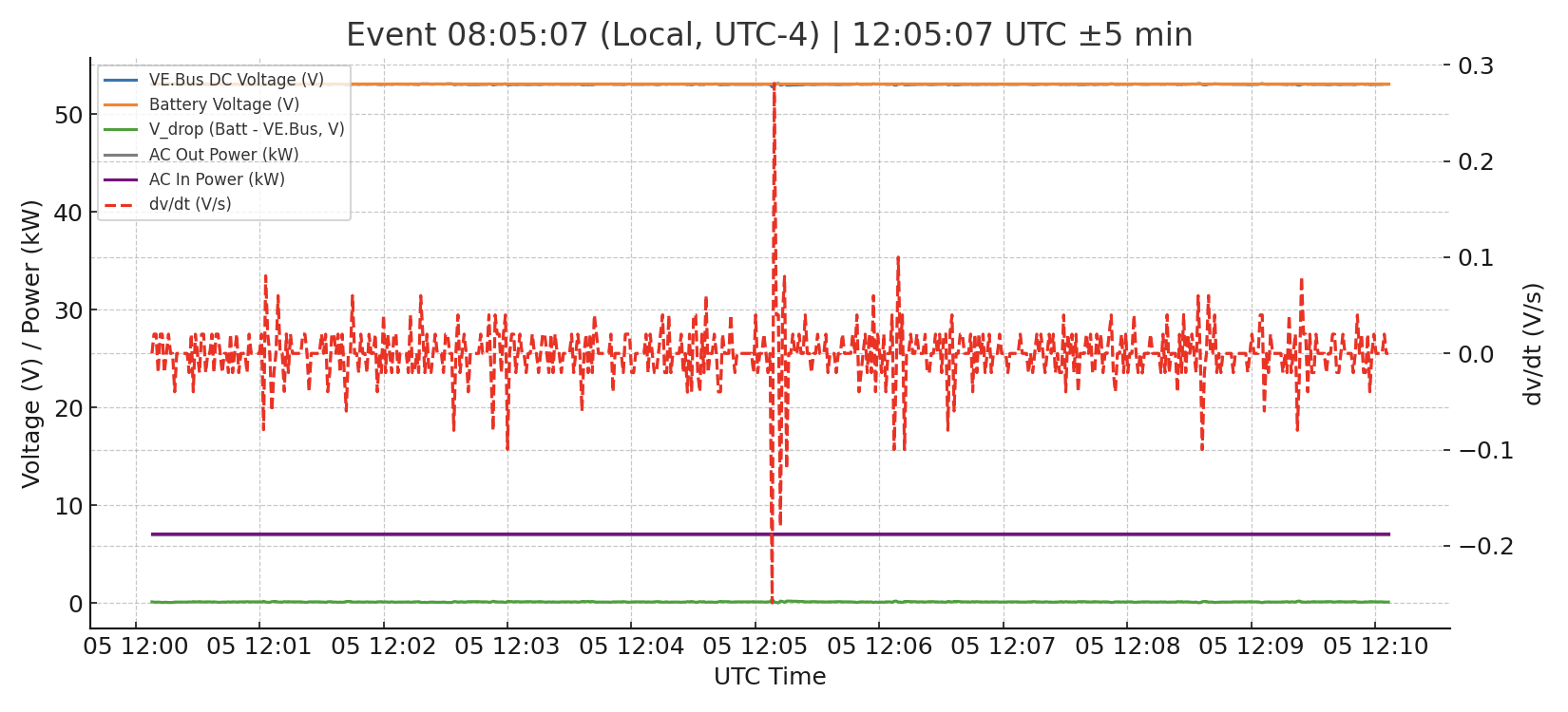
| 08:04:27 | 12:04:27 UTC | 52.78 | 0.28 | 7.10 |
| 08:05:07 | 12:05:07 UTC | 52.78 | 0.28 | 7.10 |
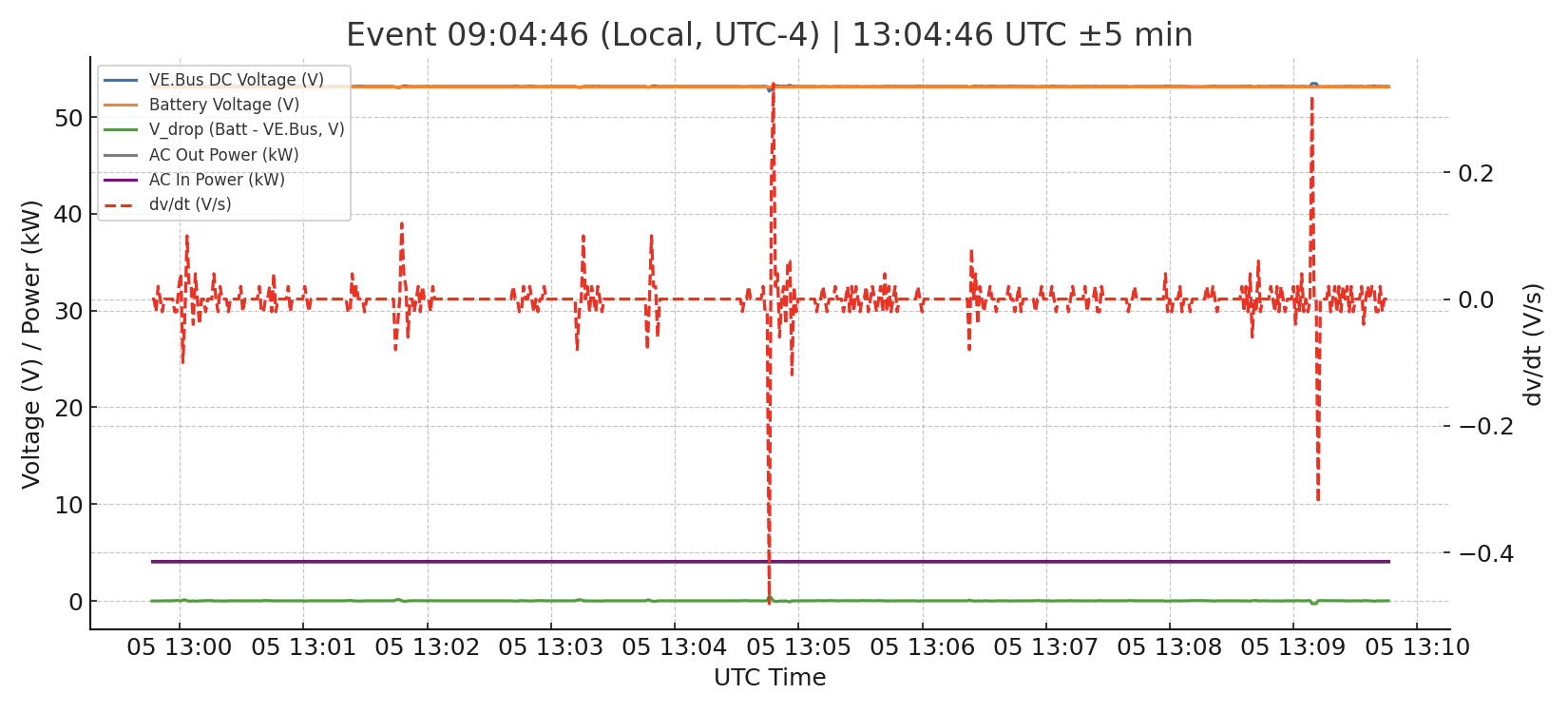
| 09:04:46 | 13:04:46 UTC | 52.66 | 0.48 | 4.10 |
Event Plots (±5 min each)
Event 1 — 01:37:29 (local, UTC-4) | 05:37:29 UTC ±5 min
so was pretty sure this system was going to fail which it did. Function continued to degrade. Had to shutdown the system and bypass due to L1 inverter failure.
Stuck relay throwing power into the grid
Constant error showing low battery on L1 of the split phase system
ABSOLUTELY NO RESPONSE OR HELP FROM VICTRON despite the dealers escalation of the problem. Considering pulling it and throwing in the trash. No support what so ever. For anyone considering buying Victron beware.
The system was running as ESS — Optimized battery life. Thus allowing solar energy to offset the utility usage. The generator is for power loss of the grid. Right now only getting 15% of needs from solar panels. That will be expanded to 35% if I can ever get the victron system running.
I must report my disappointment with Victron. I am still waiting for an RMA to return one of the Quattros. All of this stemmed from a bad Quattro. I am pretty sure one of the Quattros had a problem from the day I got it with measuring battery voltage. The system eventually failed with that great smell of burning electronics. The ACinput 1 relay is frozen open. I purchased a replacement unit because I couldn’t get an RMA. The system is working fine now. I wrote custom red-node control programs that function without the stress of ESS and maximize solar energy usage.
Sadly I cannot recommend Victron to anyone due to non-existent support. The dealer tells me they are still waiting on Victron for an RMA. It’s been a month. I have sent several people to purchase EG4 systems.