Brinkley Z 3100 5th Wheel that will be used in Western USA on 15A/120v and 50A/240v Services.
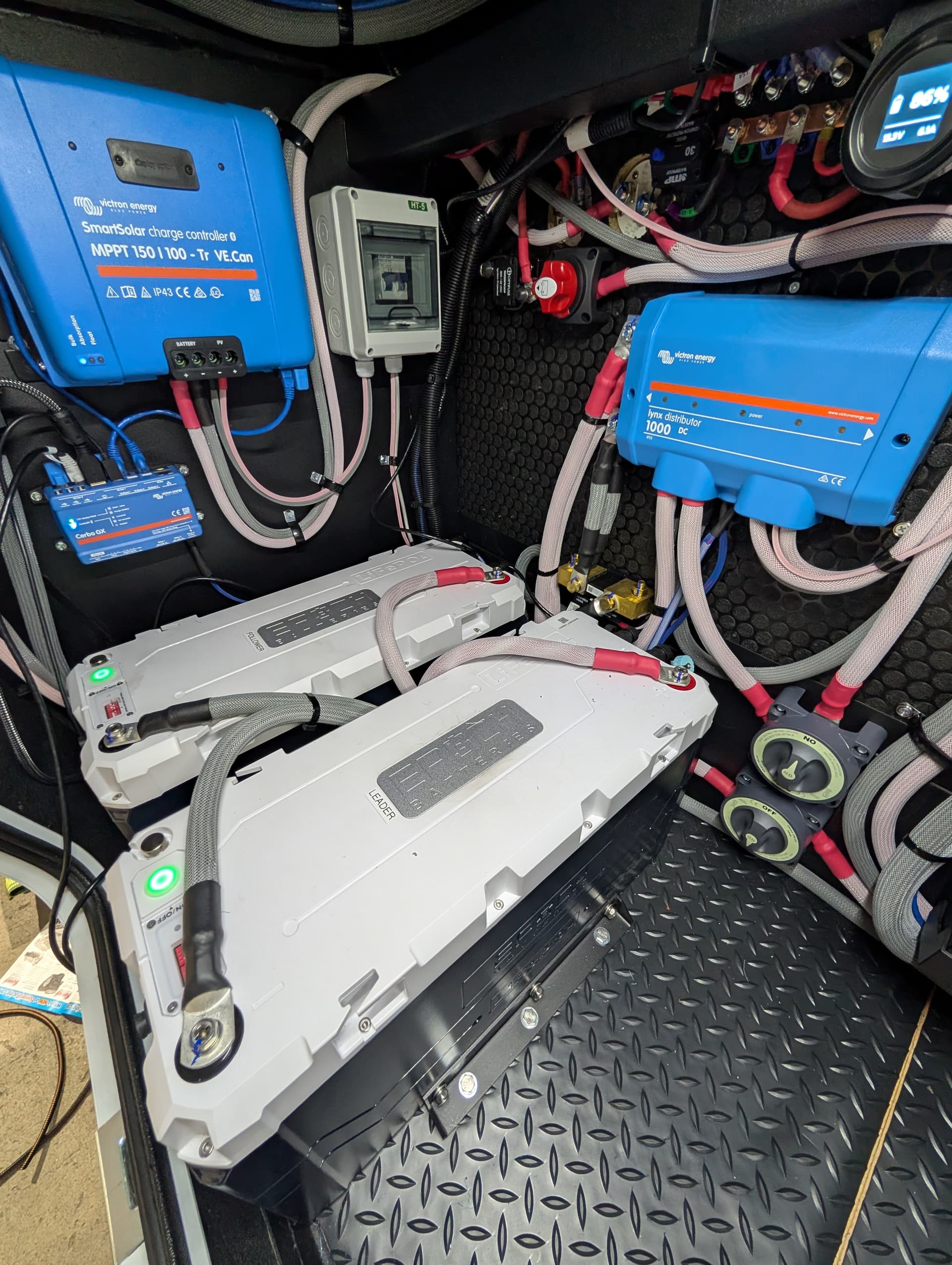
x2 MP-II 2x120 running in parallel
x2 Epoch 12v 460Ah In Parallel
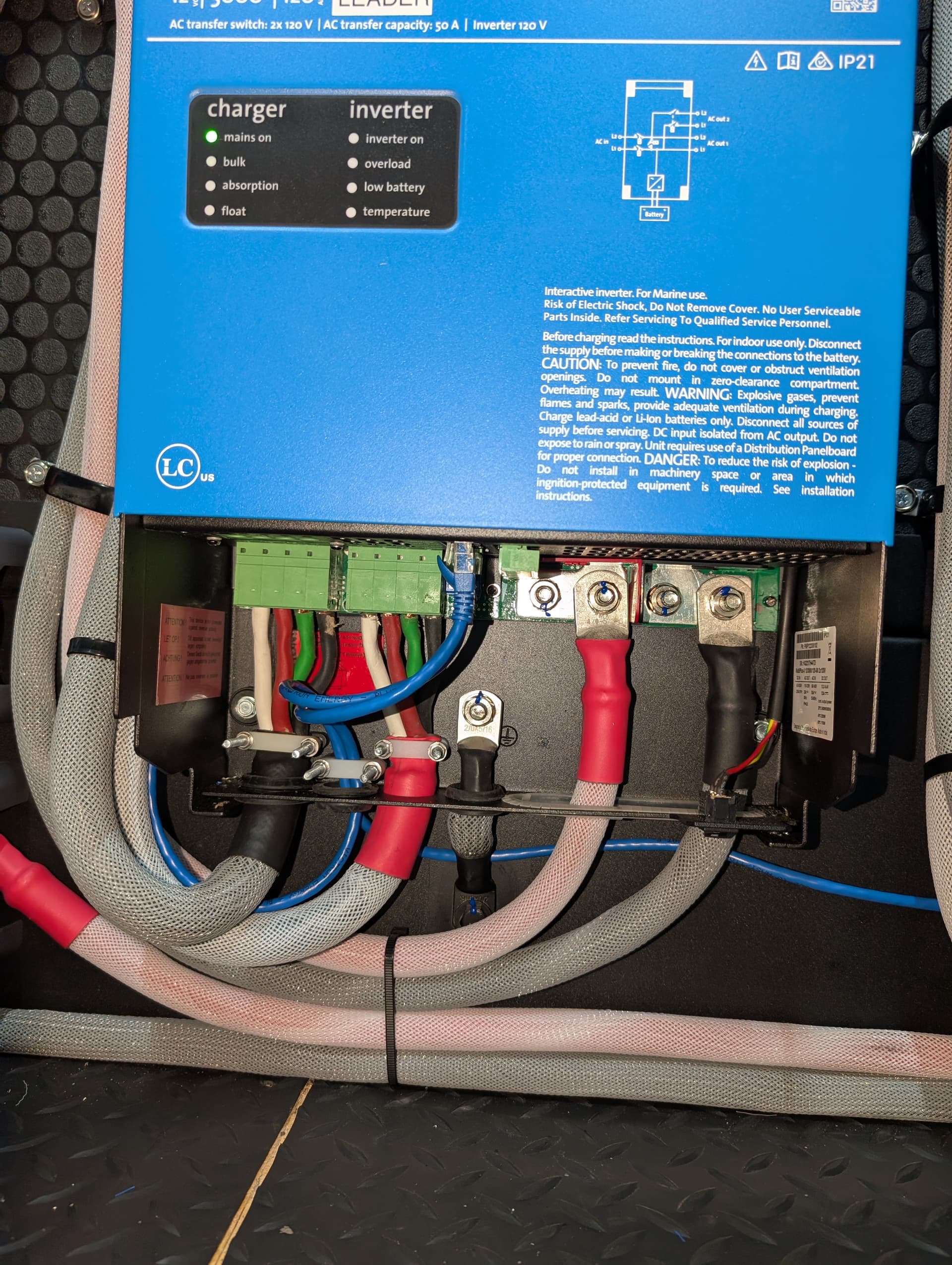
Equal Length AC and DC Cables
Cerbo GX controlling
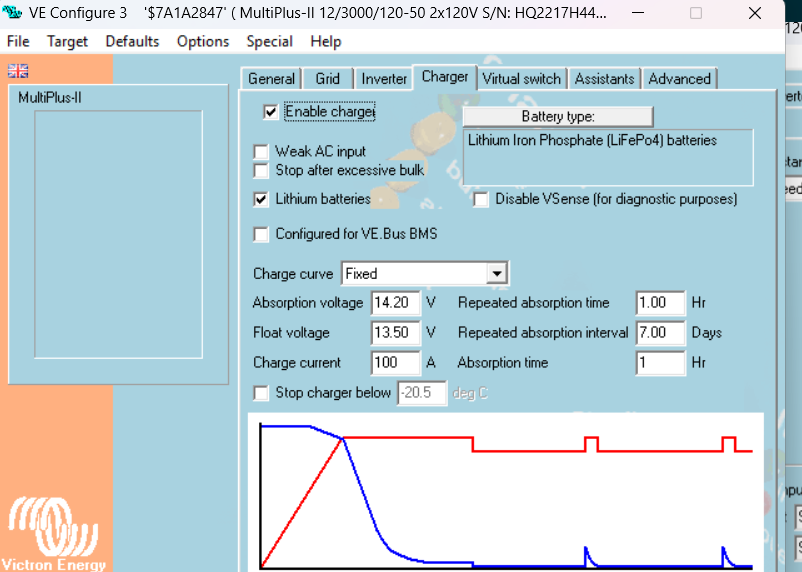
Latest Firmware on all units (MP v556, Venus v3.62)
Lynx Distributor acting as bus bar with x2 400A Victron 80v Mega Fuses
The issue:
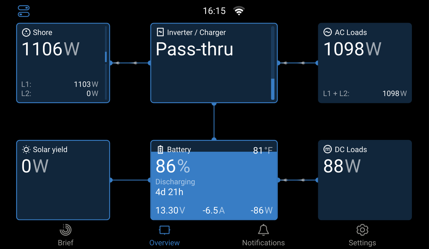
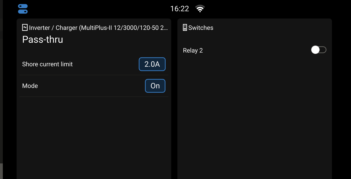
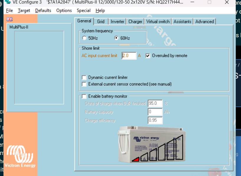
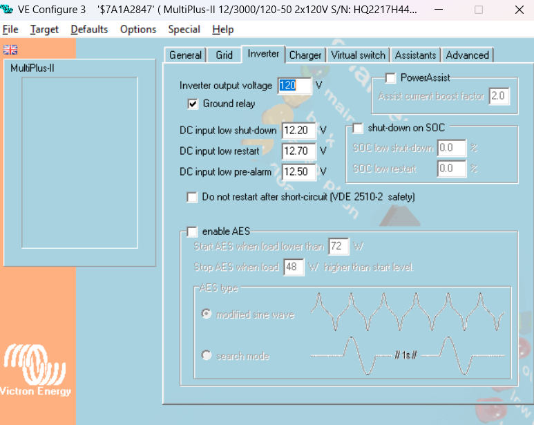
The system does not seem to be respecting the input current limit of the System. In the first picture, the system has an Air Conditioner running that is pulling ~1100W. But my current limit is set to 2A (see 2nd pic). In VE.Configure I have turned off PowerAssist, because otherwise, we would not be able to Current Limit below 19A (9.5A x 2 MP = 19A). If the Client only has access to 15A Circuits they could very easily trip the 15A Breaker (x2 Air Conditioners ~= 2200W or 18.3Aac). I am wondering why the Multiplus’ are pulling more than 2A-4A from Shore if it is set to 2A? How and why is this possible? Additionally, it is not heavily dis-charging because of this. All Battery Discharge Energy is due to DC Loads. So I know it is not going into some Faux Power Assist mode.
Any help would be appreciated. More photos below. No Virtual Switches or Assistants used.
With power assist disabled, the ac input limit will only limit the battery charging output to try to stay under the ac input limit. If the ac demand goes above the ac input limit then battery charging is effectively disabled (dc charger output set to 0) and the ac load will continue to be supplied until the breaker trips. Disabling power assist effectively ‘disables’ inverting while the ac input is connected. The minimum current limit with these inverters in parallel and power assist enabled is 18.6 amps.
You have 2 basic options with the existing equipment if you require lower ac input limits. (There are other options, but additional equipment would be required)
Reconfigure the multi’s for split phase and disable ‘switch as group’ in the configuration. If there are multiple aircon units make sure they are on opposite phases.
Provide an mk3 adapter to the customer and instruct them how to reconfigure a single mp2 for stand alone operation when lower ac input limits are necessary. This can be done by simply switching off one of the multi’s at the physical switch, and reconfiguring the remaining unit. no additional wiring or switching is necessary. Obviously being that this is a customer rv this would be the least desirable solution. (I use this method in my personal rv)
As stated above, there are other options as well but these 2 would be the simplest.
I am interested in Option 1. When we do this installation with 2 Multiplus-II 2x120 units, we configure them in Parallel in VE.Bus System Configurator. This is because we take the 50A/240Vac shore power connection and parallel into both Inverters, then their outputs are combined and sent to the AC Panel.
We do this because we do not want our customers worrying about what loads are on L1 vs. L2 when on a shore connection with a single line (15A, 20A, or 30A). In installations done in split phase with Two Multiplus 12/3000/120-50 120V (PN: PMP122305122), we have noticed that if the customer is plugged into 30A shore power, the max charge rate of the Leader Inverter of 120Adc, is sometimes not enough to cover the Inverting Load of the Follower Inverter.
Example: A space heater plugged into L2 can pull 1800W, and the charging from the Leader is only 120Adc (~1600W), and thus, we are discharging our batteries while on shore power; while pulling a load that is well below what a 30A/120Vac connection can provide.
Our solution, we thought, was to do a parallel 2x120 Multiplus installation. This would allow a single Line shore connection to be split between both units and then be passed along to L2 from shore without having to Convert/Invert through the battery. Additionally, the customer could have access to up to 6000VA of power on L1 and L2 (not at the same time).
If we were to do a split-phase Multiplus-II 2x120 installation, would that be the best of both worlds? And how would that physically look? Could I still split L1 and L2 ACin into both units? How would ACout be wired? Would L1 for leader and follower be the same voltage and thus be able to parallel together? The split-phase setup for Two 2x120 units confuses me a little.
I hope this all makes sense… I will continue to do some research and read into the manuals a bit, but any advice would be welcome!
If you were to change to split phase you would need to rewire both inverters inputs and outputs. L1 to inverter 1 and L2 to inverter 2. That being said, there are obvious pros and cons to both a parallel setup and a split phase setup. I always discuss the pros and cons of both setups with my customers and they overwhelmingly choose the parallel option. Given that the vast majority of campgrounds and rv parks will have at least a 30 amp shore connection available, I prefer the parallel setup. With a minimum ac input limit of 18.6 (and the inverters place about a 10% buffer on that) even a 20 amp outlet will usually be fine. (Unless it’s a GFCI, then that opens up another can of worms). Unless there is a need for 240 split phase such as a minisplit or electric cooktop, I see no benefit to putting the inverters in a split phase configuration for the majority of installations. I don’t want my customers calling me on a weekend from a campground wondering why their batteries are draining even though they are plugged in.
The L1 to Inverter 1 and L2 to Inverter 2 holds even when using 2x120 Multiplus’?
And I agree, despite the issues with Parallel, I tend to think it is the better system. It is frustrating when we have customers that only have a 15A outlet at home to connect to…
It seems the simple solution would be to just lower the minimum input limit of the 2x120 to be much lower to account for at least dual Inverters. Especially given the 2x120 is obviously made for 50A serviced RVs in North America. Also, the 2x120 has a much higher minimum it comparison to other 12v/3000W Multiplus. MP 12/3000 120V is 4.5A compared to 9.5A for the 2x120.
Also, why is there a minimum limit on the MPs? It seems pointless for RV applications, but I am sure there is a reason.
Yes, when configuring 2 of the 2x120 for split phase they still have to be wired one inverter on each phase. When in split phase configuration the L2 input of each inverter is essentially ignored like it doesn’t exist. Shore L1 goes to L1 input on inverter 1, and shore L2 goes to L1 of inverter 2. There would be no connections to L2 input or L2 outputs of either inverter.
As for your question about ‘why’ the minimum current limit, I believe it has to do with the way the inverter is designed to provide power assist, while also preventing grid feedback when a load suddenly drops off. In ESS mode the minimum current limit for parallel 2x120 is 2amps, so they certainly are capable of operating under those conditions. However ESS is NOT to be used in mobile applications because of the potential to have power present on the shore cord when disconnected.