I have strange situation. I have regular phase detetcing screwdriver, you knwo that when you touch it and put it in phase (line, hot) lamp inside glows…so when i do that in sockets that are connected to grid, all ok, one shows phase and other doesnt. But when i do the same test no matter do i touch N or L wire comming from MultiPlus II that is in inverter mode, screwdriver alwasy glow…aka shows phase detected. Why?
Is this normal? Electrical stuff, motors and so on works ok, so…i dont understadn why from socket screwdriver “works” but when it comes to MultiPLus it acts like it’s broken, but it can not be broken it uses real phase and my body as groud to make led glow, so this means that N from MultiPlus is also dangerous.
Or maybe victron just makes crappy electricity? So you sayin AC power screwdriver is accurate but measuring victron it some how stops working? :DDDD Worst joke ever. I need better response than that, this one belongs to propaganda section. I would agree with you if in both cases it would show phase in grid ac and in victron output, but it only shows phase in both lines that comes from victron. NEVER EVER EVER seen incorect work of such device. And i used it like 20 years in my life.
Such screwdrivers don’t tell you how much voltage there is.
They can (but shouldn’t) be used for a quick check but if you are unsure about the result you should use a two pole voltage tester or digital multi meter in the next step.
So use a digital multi meter to measure the actual voltage before make assumptions about the quality of a product.
(L to N; L to PE; N to PE)
Also read in the manual about the ground relay (floating neutral).
I agree with Matthias here, - these “screwdrivers” just glow if there is a small current flowing. And therefor maybe 1V difference is enough. And as they are not standardized, that’s why one of these is lighting up, while the other does not. That’s why it is not an accurate reading.
An other aspect could be a neutral drift in your installation. Could have different reasons, but must not be a problem at all.
You the first who made assumtions about bad screwdrivers If from wall socket works ok, and from inverter doesn’t, it’s not logical to blame the tool.
Anyway, so i probably have earthing problem. I’ve disabled ground relay, connected ground to my grid ground and in the grid’s box (dont know term in english for this) there is bond between ground and neutral, but that bond is for grid ac. that now have my ground from inverter connected to grid’s ground too and ground relay (aka bond) is disabled.
I dont think this is the best way to be connected, but once, i think, i saw image from Victron and they sugested such connection to connect ground (PE) to grid’s ground. which is logical if grid power is down, but in my case my grid power is ON (but it’s NOT connected to inverter, inverter only inverts and have no AC in connected nor it exports to grid), so i have part of my house stuff feeded by Victron AC and rest of the house from grid both systems share single earth/ground whatever correctly it’s called.
Those neon screwdrivers will glow at anything over ~90V, dc or AC. Anyway, so i probably have earthing problem. I’ve disabled ground relay, connected ground to my grid ground and in the grid’s box (dont know term in english for this) there is bond between ground and neutral, but that bond is for grid ac. that now have my ground from inverter connected to grid’s ground too and ground relay (aka bond) is disabled.
First: Don’t disable the ground relay, except in special circumstances. If we refer to the grid side of your utility box as the upstream side, and anything that follows is the downstream side. The grid box normally provides the Neutral Earth link - The Ac then goes to the inverter, so when in pass thru or charger mode, the N-E link is in the main board. When the AC in (upstream) drops, and you are in invert mode, the Ground link is provided by the inverter ground relay.
In an unbalanced three phase system there is current that moves over neutral (an electrical enginee sizes them afeter logginga site suitably). This is actually quite normal.
Also re enable the ground relay, it creates the ground neutral bond for safety reasons.
PS also get a proper meter. You unite literally don’t know how dangerous those screwdriver ‘meters’ are. I cant believe they exist.
Without the ground relay the output voltage of the inverter is split in half (more or less).
You will have around 115V from L to PE and also 115V from N to PE and between L and N you have 230V.
(With a 230V MultiPlus)
Ok to be sure, what i suppose to do?
I do NOT have grounding rod,connected to Victron. So to have grounding i connected my house’s ground (PE) to Victron’s PE. And disabled ground RELAY. To avoid situation when Victron bonds PE + N and my house instaliation already have bonded PE + N.
But how can i have both? To have proper grounding/earthing(?) and also do not have problem of this topic?
I dont want to enable grounding relay - because this will make GRID neutral and MultiPlus neutral to be connected together which may lead to problems and so on.
Most of devices that Victron feeds are outside, like lamps and so on so i need earth to protect people if electricity starts to flow in metal of the devices and RCCBs fail or be to slow and so on to protect people. Cause it may be rainy and rccb 30mA may be still to much to kill people if they are wet. And late ron i connected victron to feed electricity to some of lines in my house. So had to disable grounding relay. If it only supply electricity to the outside - relay would help cause in case of problems it will make short and trip the circuit breaker. But in case of being also connected to the house makes a problem but i do want to feed electricity to my some devices in house cause i have too much os solar and i want to be able to use it inside the house too
Thanks both for the input.
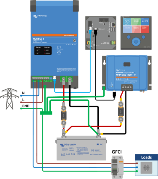
Drawn some simplified diagram to make things easier to understand.
I used this diagram from Victron which is the same as mine [i did not connect PE to the chassi/case of victron] but i just dont feed MultiPlus with grid power
[quote=“Tomas, post:10, topic:33039, username:tommix”]
PE + N and my house instaliation already have bonded PE + N
[/q
Is this before and after the inverter?
The inverter connects its neutral to ground. Which is usually regulation as gnd/n bond is made a source. With no grid the source is the inverter.
As you cna tell im not english speaker but i dont understand why it sos hard for you to understand me? I said many times inverter is NOT connected to the grid. Or what are you saying? To enable relay? to disable?
Ok will try to explain the last time if i fail than i give up.
What i want is to have 2 different energy sources GRID + SOLAR (multiplus).
Those 2 energy sources feeding end devices. Grid is never connected to MultiPlus.
If Solar fails, battery dies and so on - end devices will auto swicth to GRID (ATS installed).
Because many items that are fed by MultiPlus is outside in backyard, i wanted to have earth connected, but i do not want to make new one by diging earth putting rods and so on. So i connected AC OUT’s PE wire to GRID’s PE, cause grid have good, by standards made earth.
To NOT have 2 PE+N bonds as per every textbook, i disabled BONDING in Victron. So only in grid’s utility box bond exists.
The problem is that that bond is between grid’s N and PE, not victron’s PE and N. Thats why i have “phase” on neutral (as per my udnerstanding).
IM AFRAID to enable bonding in victron because this would mean that PE wire will be connected (bonded) to GRID’s N and with Victron’s N. IS this safe?
i want to ground end devices, not victron chassi, nobody will touch victron. So my end devices are grounded because their PE wire is connected to grid’s PE. So when end device fault current goes into end device’s chassi it goes to PE (as with all metalic devices in market). And end device’s PE is connected to grid’s PE. so everything is logical and should work.
Also all devices connected to RCCB for double safety.
who’s using GFCI ? it looks liek you read someone elses text not mine, with every piece of info i get response about non related stuff. Maybe im lcking infoa nd yours lookes like not related. But for RCCB to work ground is not even used at all. So in my case rccb will work.
So if i enable ground relay and 2 DIFFERENT energy sources will be connected together via N is not an issue? asking this for a 5th time… dont know how to ask more directly.
So looks like mys etup is correct and ground relay MUST be turned off and floating neutral is just side effect of setup which is correct, but with side effects.