Hi, I found it confusing to read Victron Wiring Unlimited and to have system schematics IMHO contradict eachother. Could you please elaborate on the correct way to distribute power within a large battery bank.
I’m wiring a 100Kwh batterybank consisting of 6 15Kwh 48v packs to 3 Multiplus II invertor/chargers.
Wiring unlimited states:
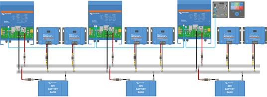
In the schematics I find:
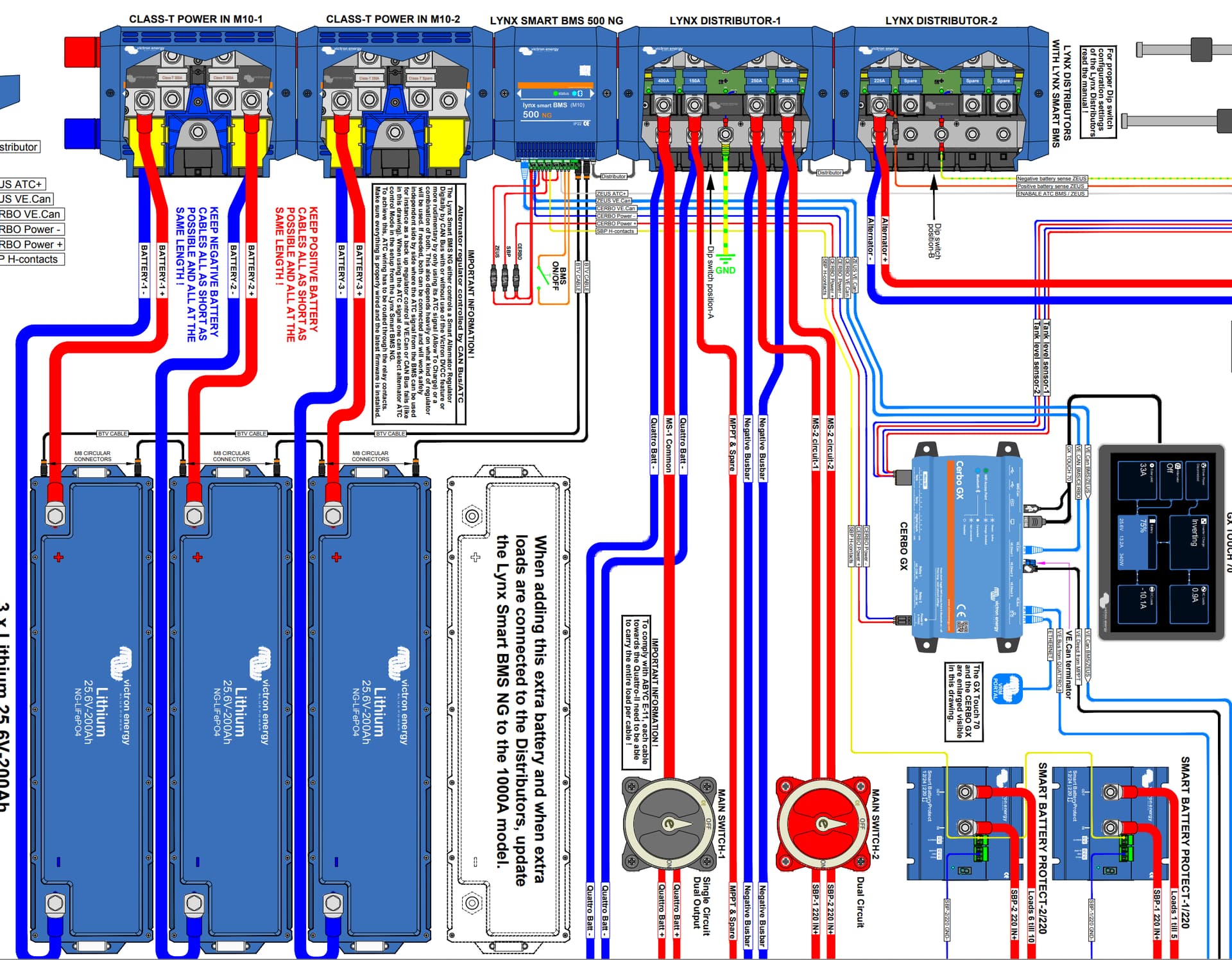
Which is correct for not unevenly loading/unloading the first connected battery?
A: Wiring unlimited is right and I should alternate battery and Multiplus or
Thus: [battery1][invertor1][battery2][battery3][invertor2][battery4][battery5]][invertor3][battery6]
B: the schematics are correct and I should the battery + and gnd wired to opposite ends of the rail on the input side of the lynx distributor).
Thus: [invertor1][invertor2][invertor3][smartbms(as contactor)][battery123456+][battery[123456 GND]
Please adivise and provide an understandable explanation.
Thank you. Kind regards.