It is unfortunate that your system does not work in the way you expect.
Mine works following the charge state reported by the shunt and the inverter charger settings (charging curve and times). I chose this way because the shunt is a more accurate measure of voltage and current as verified by other measuring instruments.
Please let us know if/when you find with a solution
This is the very same problem as in JK V17 BMS. It’s not really flipping between charging and loading, it’s just a display result of bad software in the JK BMS. This happens not only at absorption, but every time when PV-power and load+selfconsumption is almost the same.
When you measure the current to or from your battery with another tool, you will probably notice that charge currents are measured quite accurate, but discharge currents are measured 20% to high. When my BMS displays a discharge current of 18 A my independent amperemeter says it’s only 14 A.
This behaviour has been introduced with one of the last V17 firmwares. Since then the BMS reports the SOC quite correctly.
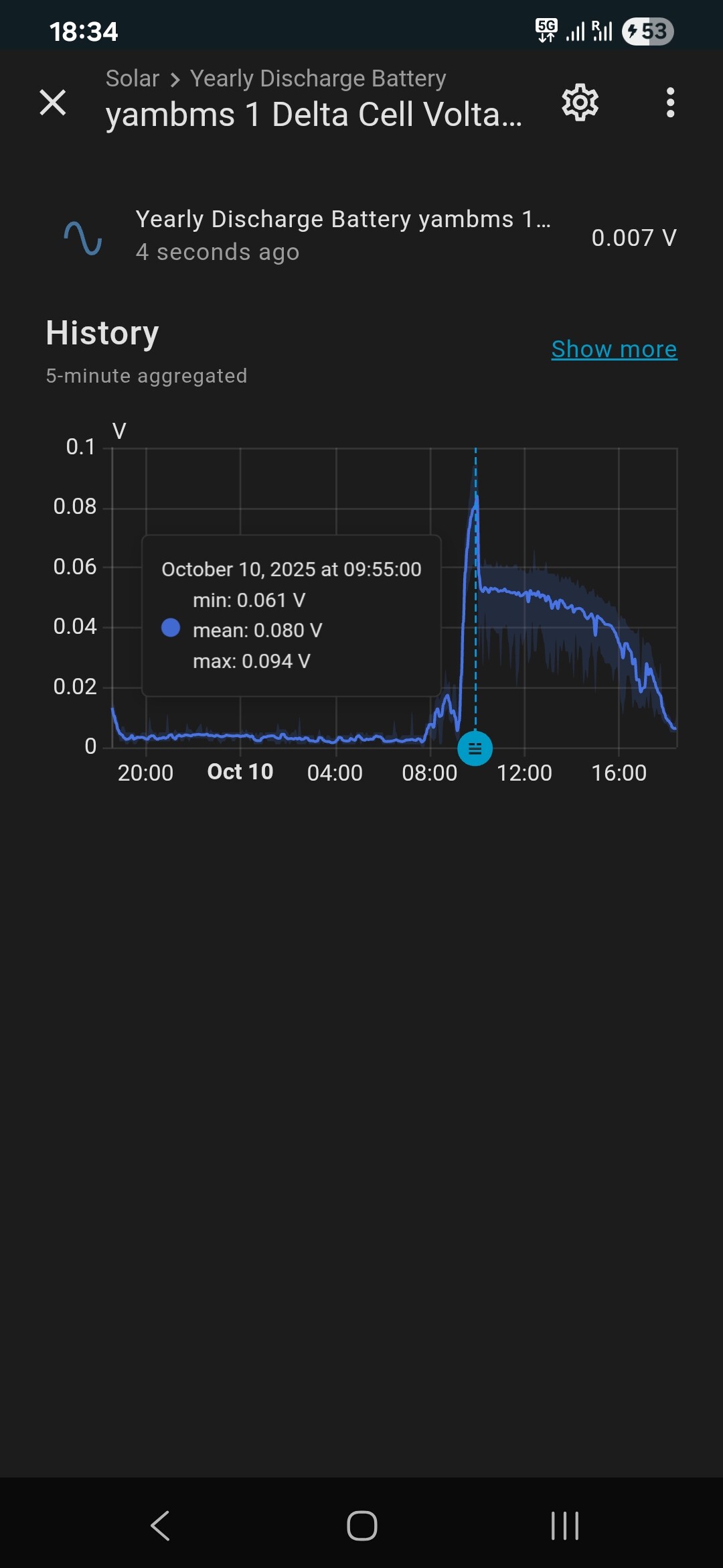
I’m pretty sure that the change in the voltage difference between the cells has nothing to do with the jumping. You’re currently in the absorption phase, and that’s where the balancing of the cells takes place.
My cells were already very well balanced from the factory, and to even begin balancing, I had to reduce the trigger difference from 10 mV to 5 mV. I set my system to start balancing as soon as the first cell reaches 3.45 V and the cell difference is at least 5 mV.
But to be clear: the problem of the display jumping between charge and discharge has nothing to do with Victron. It’s coming from the JK BMS.
On my side, the unbalance is starting when the cells reach absorption and current is under 20A. Until there everything is fine.
The problem is somehow related on victron ecosystem. For example if I use mppt (standalone) to charge the battery, everything works great. Bulk, absorption, float, all perfect. Means that jk is working correctly until is added to multiplus, cerbo, Ess.
In this case you probably don’t have an inverter running and therefore you don’t have a load on the battery. I have already told you that the jumping in my system can not only bee seen at a full battery, but also always when AC load + self consumption is almost the same as PV power. In both cases the system is close to zero power from the battery, and should only jump between a few watts in and out. But because of the wrong current measurement of the JK BMS the jump distance is much larger.
Please: just do an independend measurement of the current which is going in or out the battery. In my video you can see the charge/discharge power is jumping from +500W to -500W in not time. In my grid the Multiplus-II is not allowed to follow the load faster than at 400W/s, so this alone would be a good sign that there is no real power jump. But just see at the values from the MPII/cerbo in my video: neither the AC load nor the power going to the grid nor the solar power are changing. And this is impossible when the battery power is jumping with 1000 W difference.
No, the values of the battery in my case as well as in yours are reported by the JK BMS. Victron has nothing to do with it, and the victron numbers clearly state that there is no real power jump!
The JK BMS has problems measuring small currents… mostly during balancing.
However, since you want to set up a 12V system, there is nothing standing in the way of the JK BMS. With this low voltage, you have larger currents flowing through the BMS, which can then be measured more reliably.
With larger 48V systems, you have small currents in the base load… which can cause problems with the SOC over a longer period of time.
There is now also a current FW that fixes minor problems.
But if the shunt was poorly constructed, even that won’t help
No solution from my side. I’ve reported to JK support and I hope they can improve the firmware in the future. Until then is working like this. The bms can is disconnected from cerbo, and I use BMV-712 for controlling the charging.
Maybe Victron developers can do something to improve the compatibility with Jk. Are many users with same problem. I’ve built some batteries for Deye and Easun inverters and everything works great there. Somehow only with victron are the problems…
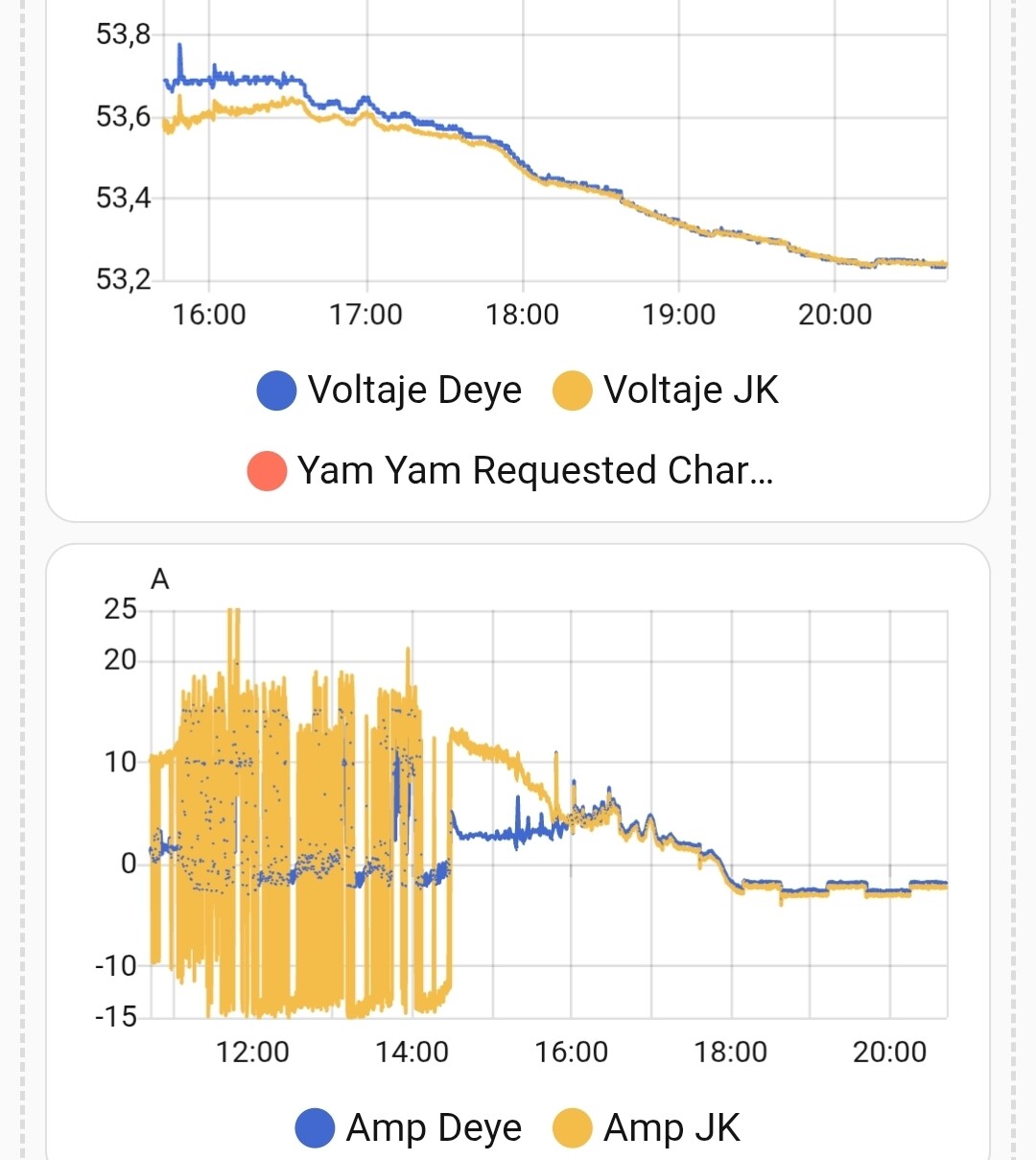
an - 15A is a little big noise I do see + and - 3.2A around 0 amp.
Reason JK is measuring peek current and not average current.
These peek currents are real there, multiplus II are producing them.
With DC current probe an oscilloscope, you can see that the DC current is real noisy.
At the moment you disconnect grid input this noise is way less and JK can measure under 3.2 amps.
JK never managed to change their way of current measurement, just use smart shunt or lynx shunt for SOC and current measurement.