Home ESS between Rennes and Fougeres, France

Hello

I started with AC-coupled PV Hoymiles inverters for self-consumption, under the regimen the french grid operator allows (Enedis CACSI) up too 3000Wc without too muchn paperwork, which I admin I’m not very fond of.

First 1500Wc with 4 modules in early 2023

Then 3 additional modules bringing it to 2700Wc in late 2024

With this I have a DIY water heater PV router.

With the uprade I ended up with PV excess I could not entirely shove into the water heater. Adding to that, my local grid has a below-average reliability that is unlikely to be a transient condition, the charm of living on the countryside.

So I took the dive and added an inverter :

  • Multiplus-II GX 48/5000
  • 2 Pylontech US5000 batteries

Final result with the MP-II besides the main electric panel

I had to cram all of this in a dwindling available space, as its placement had definitely not been something I had planned for when we renovated this house in 2021-2013, a refresh from bare stone walls with little else being kept.

I used Legrand DLP trunking to hide the cabling, with the added bonus that you can clip sockets on it, I used that to keep an RJ45 to expose the VE.Bus connector so I don’t need to remove the Multiplus cover to use VEConfigure with the MK3.

Hiding the cabling between this trunking and the MP cable glands needed a little improvisation, I used 20mm rigid conduit.

And to hide that, as well as the Multiplus power switch that’s way to exposed to mishaps, a custom made cache from a bent plastic panel.

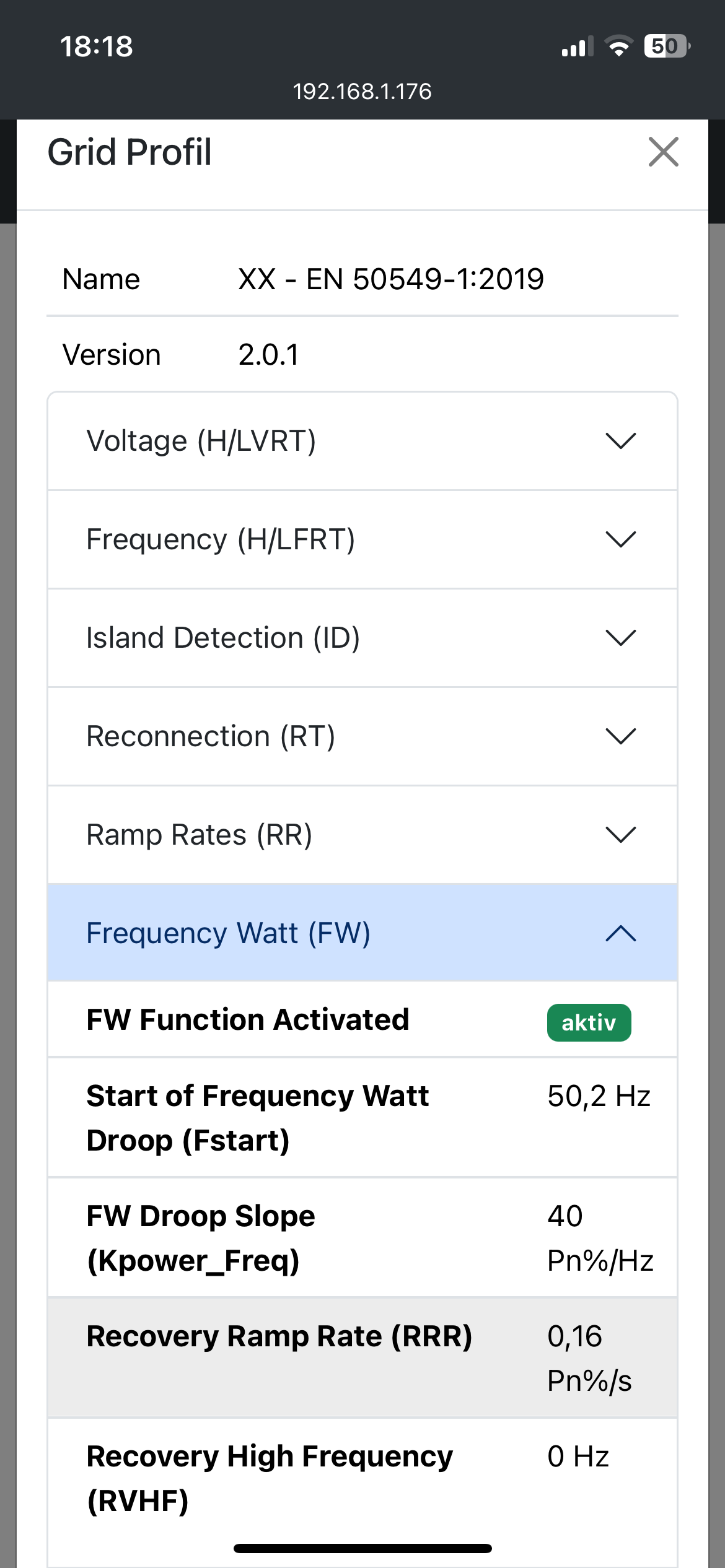
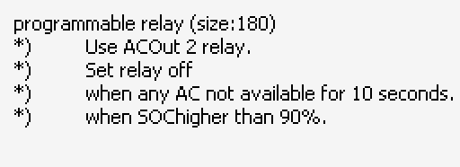
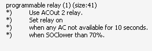
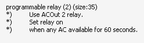
The PV inverters remain AC coupled. Since Hoymiles is so far not certified by Victron (I hope they could be, someday not too far) there is a risk should they fail to timely limit / cut their power while off grid when the battery is fully charged.

I have considered the options of DC-coupling my PV, but the scattered locations, cable lenghts, made this unpractical and unreasonably expensive.

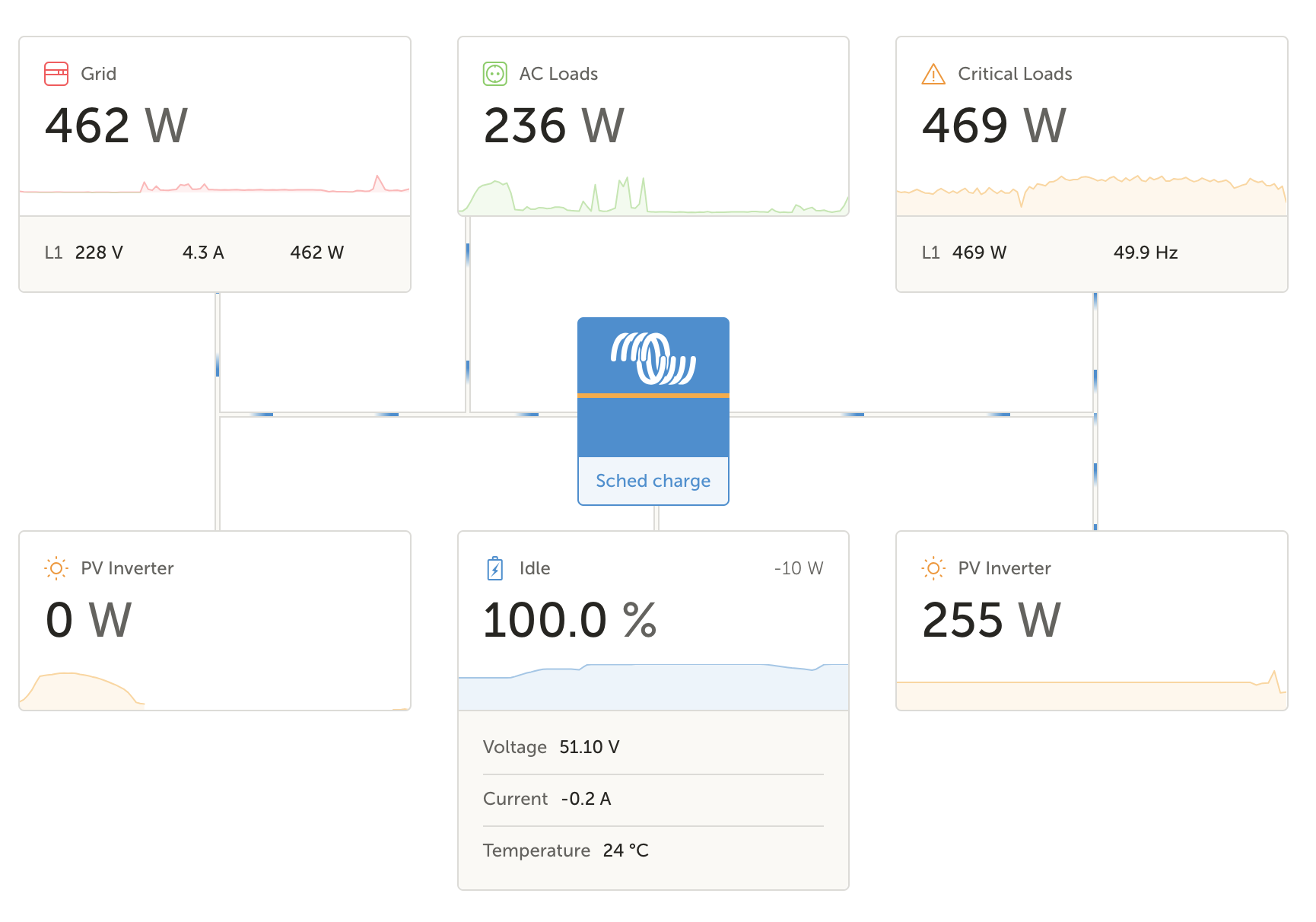
So, they remain AC coupled on the MP input side.
I have, however, added switches on the panel that let connect them on the MP output, under close supervision, in case of emergency, such as a long grid outage during day, to top up the batteries and see them through the outage without cutoff.

On the automation side, I’m really just starting, this system has been running less than 2 weeks.

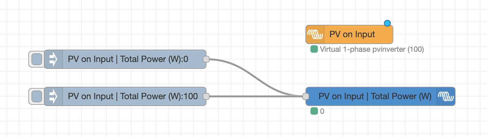
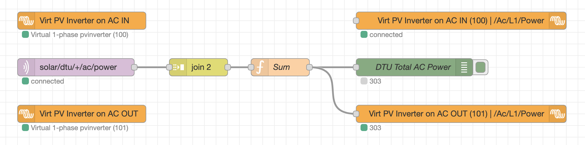
Still looking at the possibilities of nodered, I was already planning to run one on my homeserver but having one directly on the GX controller is definitely a perk for availability.

Right now I have a flow for my water heater, which still needs improvement to work well with ESS.

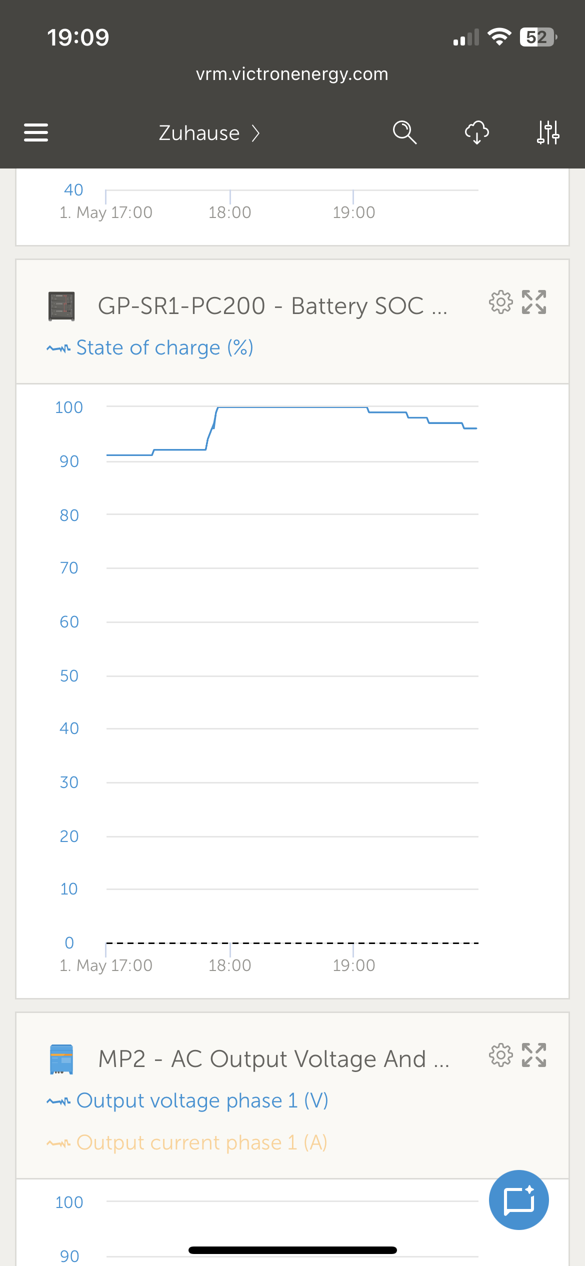
What I’m looking for is to let any PV excess of the day go into the water heater until it’s charged, then let the excess be used by the ESS for the battery. Ideally, with the batterylife algorithm still kicking in when needed to raise the ESS active SoC.

I ran across this

which is interesting but right now I’m not wanting to modify the OS without knowing where I’m going. It’s not as if I had a lab MP; if I screw the one I have I’ll have to deal with the outage while I reinstall it.
I am also keeping an eye on the memory usage of the MP-II GX board, since this model has only 512MB and with nodered loaded it’s already quite filled, that’s an additional factor making me wary of adding running services, third party or not, on the OS.

Well, while the hardware implementation is mostly done, I still have work to do to bring this system to expectations.

4 Likes

Belle installation ! Très propre, j’aime beaucoup votre solution pour cacher les tubes en bas de l’onduleur.

Pour le couplage AC, si vous n’êtes pas certain que les onduleurs se déconnectent bien en cas d’augmentation de fréquence, il y a la solution de les raccorder sur AC out 2, et de programmer le relais avec trois assistants pour couper AC out 2 si pas de réseau et soc>98% par exemple

Il me semblait que la sortie AC2 déconnectait dès qu’on passe off grid.
La possibilité de commuter les onduleurs en aval est pour pouvoir recharger la batterie pendant une panne de réseau, avec la contrainte de surveiller et déconnecter à temps pour ne pas approcher la zone d’incertitude.
Je peux aussi faire ceinture et bretelles en réduisant la puissance des onduleurs par la DTU (j’ai une passerelle OpenDTU) quand off grid et que le SoC dépasse un seuil.
Même si je ne miserais pas entièrement dessus, car l’automatisme peut être défaillant et le dégât potentiel sur le multiplus est réel.

For those who wonder, this is about my setup to move AC coupled PV (hoymiles, not certified with victron) downstream of the inverter. The suggestion was to use the AC OUT 2, however I believe it always disconnects when off grid. And my aim is to be able to charge the batteries during long grid outages, with the constraint of keeping a close eye and disconnecting the PV from the inverter before the SoC is too high.
Another safety I could add is to limit PV power via OpenDTU when off grid and the battery Soc reaches a threshold. Though I’ve no intention to leave that unsupervised; if the automation for any reason, fails, the damage to the inverter can be very real.

Par défaut, le relais ACout2 est deconnecté si pas de réseau, en effet.

Mais il est possible de modifier ce comportement avec l’ajout d’assistants dans la programmation du multi.

Je m’en sert souvent pour piloter la résistance du chauffe eau en site isolé quand les batteries sont pleines.

C’est bon à savoir.
Maintenant, comme je ne le savais pas, je n’ai pas prévu la place dans le tableau pour les disjoncteurs aval de AC2.
Si je veux rester cohérent, les disjoncteurs de protection de sortie du MP-II sont dans le tableau ESS, qui n’a plus qu’un module de libre; un 32A tiendrait, après ça passe généralement en 2 modules.
Réflexion à faire, si je peux exploiter cette sortie dans le circuit sans devoir faire un patch sale.

Bonjour @pkannoglou

you can integrate the Hoymiles with OpenDTU and OpenDTU-dbus. Each single inverter will show up. I have 4 hms and 1 hm running.

Factor 1:1-rules is satisfied, so you can connect the Hoymiles to AC-out. They continue during grid failure. You should configure frequency shifting. In case of 100% SOC, the MP2 increases frequency and the Hoymiles will reduce power linear until switch off. Double check the French grid code, but should be similar to German grid code referring ARN-4105. With OpenDTU, you can read out the grid parameters in your Hoymiles and you can see the frequency shifting events.

Frequency shifting is the official method to throttle AC-PV when off grid and each grid tied inverter must implement it.

You should add at least one MPPT to restart your system from sun during grid failure when SOC is 0%. This is named “black start”.

With current MP2 you can control AC-out2. Using relay assistant, you can open and close AC-out2 based on SOC to cut non-critical loads.

I use a Shelly for my water heater.

Have fun and enjoy the sun in your nice house!

Thanks for the info.

That’s henne49/dbus-opendtu, right ?
I see you have HMS & HM devices mixed, so, I guess, the 2 types of radio (NRF & CMT). Do you have a dual-head opendtu (I don’t), or you run 2 instances of dbus-opendtu, one for each DTU ?

Having some modules DC-coupled with an MPPT was an option I considered before committing in this installation, but the cost was too high. The modules groups are respectively 38 meters and 16 meters from the MP-II and battery, so I had to choose between low voltage and expensive cabling, or voltage above the 120Vdc limit that makes an insulation controller mandatory by regulation.
So the cost of the black start capability wasn’t worth it. I really hope the grid reliability doesn’t degrade further that I would regret that decision.

The possibility to use AC2 and reprogram its relay is something I’ll have to look into, as yann also suggested.

About frequency shifting, some people including my distributor have expressed doubts that, until tested and validated by Victron, there is a risk (that would be off-warranty).
Even if the MP-II shifts its frequency up based on SoC only (not feed-in power in AC out), the moment the grid fails remains a dangerous situation if the inverters are not quick enough to reduce.
In this case, there is nowhere for excess power to go, except to fry the MP if it lasts for too long, or maybe cause it to cut off.

Hi @pkannoglou

I have the open alliance app fusion board with both radios.

All grid tied inverters certified for the European grid need to be fast, when switching off based on frequency above some 52hHz.

Frequency shifting is the only method supported by Victron while off grid and official supported with Fronius.

The factor 1 rule shall ensure the energy while switching off OV-inverters can be absorbed.

I tested it with my system successfully. HMS get throttled and switched off. The hm-600 get switched off but does not restarts as it has a wrong parameter for restart frequency. Without a Hoymiles DTUpro I am not able to change the parameters.

Please find attached screenshots from grid code setting of my HM-600 and HMS-2000

The second screen shot show high frequency recover = 0, why the HM does not restart.


Good info to have at hand.

From what I’ve gathered looking into other posts here that quote hoymiles, those micro-inverters rather tend to cut abruptly and too early, going straight from 50% to 0, and not to wake when frequency drops back to 50Hz.
In any case, if this happens I’d have to manually cold-restart the inverters when the battery can receive charge again, by disconnecting/reconnecting them to the MP-II.

One thing I must decide quickly is if I’ll move the PV inverters to AC OUT 2.
If I do, I may have to do so before I take the regulatory inspection otherwise their visa might be moot even for this little change. I’ll be charged for this paper, it might as well remain valid.

What I understand is, by default the AC2 will immediately disconnect when grid goes off, so at this stage there should be no additional vendor warranty risk tying PV inverters there rather than upstream.

I wonder about how the MP-II will measure power flows in this setup.
Is there an accurate diagram somewhere of the MP-II power wiring with its relays (I’ve seen that I think) and measurement current transformers ?

@pkannoglou

AC out 1 & 2 are connected parallel with the 2 having a relay.
The MP2 has an internal current meter which measures both outs together.

Yes, by default relay for out 2 opens when mains is lost. Behavior can be changed by “relay assistant” in VeConfigure.

Yes, PV inverters on our 2 which get disconnected on loss of mains would be save, but the same as connected on AC in.
It just gives the opportunity to change it via the relay assistant without rewiring.

My Hoymiles can be throttled. The ramp down power out put defined in “frequency watt” shown in picture above.
50,2Hz = 100%
With each additional Hz, reduce bei 40%.
You configure the ramp rate for your MP2 in VeConfigure in PV-Assistant (off grid) or in ESS Assistant for ESS.

The HM-600 has a wrong setting for recovery high frequency (after shutdown at 100% SOC and no consumption) why it needs a power cycle, e.g night.

I discounted mains and waited until 100% SOC while pulling 2-3 kW. The MP2 increased frenzy to 51.x Hz and throttled the Hoymiles partially.
My SmartMppt reacts faster on throttling. Though the Hoymiles stays at around 2kW and the SmartMppt regulates the power changed due to clouds.

In any case, I would recommend to add a single panel with a small MPPT to recover from low SOC. The single panel would power the DC bus, making the MP2 starting and building a micro grid (island). As soon as the micro grid is created, the Hoymiles will start and provide the majority of power.

I hope this helps you…

No joy @pkannoglou

Pls find attached advanced graphs from May 1st 2025, when I disconnected the mains.

100% SOC was reached appr. 17:45.
Frequency increased to 51,1Hz.
Hoymiles and MPPT (purple) throttled.
The MPPT increased power appr 18:10 and 18:50.

I have 1x SnartMppt 150/45 and 3x HMS-2000, each with 4 Trina Solar Vertex S+ 425Wp panels. Plus a HMS-1000 with two Vertex S+ 425 and the HM-600 with two Vertex S+ 380Wp.


In Germany, all grid tied power producer need to reduce power based on frequency according VDE-AR-N-4105 since 01.09.2005.
Starting at 59,2Hz, the producers need to reduce power linear anti 51,5 Hz where they need to switch off.
Though all Hoymiles support this throttling.

The time to switch off in case of conditions outside normal operation is defined as 200ms max.

  • loss of mains
  • High frequency
  • Low frequency
  • High voltage
  • Low voltage

I assume, France has similar requirements as we both are part of the connected European grid.

The “factor-1-rule” should ensure the surplus power during the event of loss of mains, can be absorbed by the batteries and the transformer in the MP2. Though the PV inverter need to throttle down to zero within 200ms, which they do.

Is there something special to disable AC OUT 2 default relay behavior, aside from adding assistants for it ?

Like this, switch off above given SoC

Back on below a threshold with some hysteresis

And back on when grid comes back

à partir du moment où il y a des assistants qui l’utilisent, le comportement par défaut est inhibé il me semble

Dans tous les cas, au détail de la config près, la possibilité change la manière de câbler.

Je vais garder mon sélecteur pour mettre le PV au choix sur le MP2 OUT 2 ou sur l’arrivée réseau du TGBT, de la même façon que pour OUT 1 je veux pouvoir mettre le MP2 en bypass et garder le reste en fonctionnement, charges secourues et production PV.

Mais je vais ajouter un disjoncteur pour OUT2. J’en profite pour insérer un interrupteur différentiel HPI en amont des couplages PV AC.
La question réglementaire sur ce point devient académique et pas un potentiel motif de rejet, avec un HPI 30mA en amont des AC 30mA des coffrets PV, je devrais garde un brin de sélectivité sur les courants de défaut puisque les HPI ont une courbe retardée.

Thanks to @yann and @BjoernK for the recommendations, I have implemented this in the cabling and assistants.

I now have

  • AC OUT 1 to critical loads subcircuit of the main electrical panel
  • AC OUT 2 to AC coupled PV inverters

Both with a bypass inverter each, that allows to reconnect them directly to the grid in the event of a maintenance of the Multiplus.

I programmed the AC OUT 2 relay according to my 3 Veconfigure screenshots above, and changed the ESS config to enable frequency shifting.

One disturbing thing though : I have the Victron AC Current sensor measuring the PV power output, and I had already noticed the thing is really inaccurate, unless I’ve a faulty one, but my vendor did seem to find it is within tolerance.
At power above 1000W the error is less than 50W, acceptable. But when the power nears 0, I still get a reading of 200-300W, and that’s more of a problem.
It’s not even crosstalk of the neighbooring power cables in the sensor’s aux input, I tested the sensor with a free cable out of the main conduit and the result was similar.

The more annoying thing is, this reading


is the sum of the actual Multiplus output power (measured by its internal current tf) and the measurement of the AC current sensor.

First, this does not seem faithful to the node label (power output of inverter/charger is a different thing from power consumed on ac out side).

And, with the sensor inaccuracy it leads to a polluted measurement.

I’ll have to change my flows to substract


from it before consuming it, wherever I need the actual Multiplus output, not a calculation of the AC OUT side power.

That, or ditch this sensor altogether because I have far more accurate measurements from my DTU. Just sad that having 2 types of micro-inverters and 2 opendtu rather than a single dual head one, it seems difficult to use opendtu dbus integration. If there was a way to feed the PV power to the GX device via a NodeRed node, I already have the DTU measurement in a MQTT topic of my local broker.

@pkannoglou

please check in Venus OS 3.6x large / node red Victron palette the option of a virtual device. Maybe there is an option for PV inverter. Then you should be able to feed MQTT into that virtual device.

BR Björn

I just upgraded to 3.62.
It gave me a little scare, everything seemed to be back online after the GX reboot but the grid meter nodes were disconnected and claming I had no such device.
Probably just the time for nodered to fetch data, it settled back after a few minutes.

Playing with that right now

I suppose that’s how it’s used; the example flows from node-red-contrib-victron (node) - Node-RED don’t seem to contain examples for this one yet, probably too recent.
Adding this lets a fake PV inverter show on VRM, input side, but the values don’t update.

Well, got it wrong the first time.
I found this sample node-red-contrib-victron/examples/Virtual Device: grid.json at master · victronenergy/node-red-contrib-victron · GitHub

Those are the nodes to use.

This works and shows in VRM

Time to go disable the AC sensor assistant and replace that with MQTT feed from OpenDTU.

Perfect

(I know 300 watts for 7 modules is not great. Thunderstorms are not great for PV performance :slight_smile: )

1 Like