I’m new to the forum and excited to join this community—greetings from Germany!
I’ve already found lots of valuable info here, and now I’d like to ask for your advice regarding my system setup.
I have a Victron setup in my campervan that I would like to optimize. Currently, I have:
Victron MPPT 100/50 (charges only the house battery)
Victron Orion DC-DC 12/12-30A (charges the house battery from starter battery/alternator, controlled by engine run detection)
Note: The house battery is a Lithium Iron Phosphate (LiFePO4) battery, and the starter battery is a conventional lead-acid battery.
I plan to add a second Orion DC-DC (e.g., 12/12-9A, possibly isolated), switched via the MPPT’s virtual load output (using the VE.Direct TX Digital Output Cable and a relay), so that solar surplus can top up the starter battery as soon as the house battery is full.
Planned wiring:
Input of new Orion DC-DC from the house battery (via fuse and relay)
Output to starter battery
Remote input of new Orion controlled by the virtual load output relay from the MPPT
Here are my main questions:
Are the inputs of Victron Orion DC-DC chargers (isolated or non-isolated) definitely short-circuit proof? Could reverse/backfeed current from one Orion into the other cause any damage?
Has anyone run two Orions with different charging profiles (LiFePO4 for house and lead-acid for starter) in the same system? Any interference or issues if one Orion supplies current “against” the input of the other (e.g., one active, one off)?
Any tips for configuration (engine run detection, voltage thresholds) to prevent device conflicts?
How critical is galvanic isolation (isolated vs. non-isolated) in this scenario, given the rest of my setup is already isolated?
Technical detail:
Can the Victron VE.Direct TX Digital Output Cable drive the Orion DC-DC remote input directly, or does there always need to be a relay or another form of isolation in between? Any real-life experiences here?
Thanks in advance—it’s my first post, so I really appreciate any help as I get started!
You can use the VE.Direct TX output cable from an MPPT to connect to the remote H terminal of the small Orion directly, but only because you want to use the Orion to charge the starter battery. The Orions remote terminals are referenced to the input voltage. If you want to do the same on the bigger Orion, you would need either a relay or an isolated remote on/off cable.
Check the datasheets for short-circuit proofness. But that would only be of interest for the output. A shortcircuit on the input just means 0V input voltage for the Orion.
Theres no reverse current possible afaik.
You might be able to define the smaller Orion as a DC load, so you could connect it to the GX device over VE.direct. But you cant use them in the same VE.Smart network.
I suggest to check your local regulations (VDE i guess) concerning grounding of DC systems in vehicles. Using the house batteries DC system with a floating/ungrounded negative pole might not be allowed. So isolation goes out the window anyway.
If allowed, using two isolated Orions, each charging the others battery, will maintain isolation.
But in general, why not connect the MPPT to the starter battery and use an Orion XS between starter and house battery? To me seems the simpler solution, the starter is kept fully charged, and the house battery can still receive the full 50A of solar if available. Or use a second 12-12/30 in parallel to the existing one to maintain isolation. Or depending on the actual solar power installed, you might not even loose any house-battery-charging power by keeping only one 30A Orion
At first, I had a thinking error: I can actually connect the input of my Orion DC-DC 9A directly to my positive and negative distribution point and control it via voltage monitoring, just like my other Orion. In my case, it switches on at 13.7V and off at 13.3V (the MPPT is set to 13.4V absorption and 14V float). After sunset, or once the MPPT is no longer supplying power, the battery voltage typically settles around 13.3V. That should work, right?
Regarding VDE, based on the information I’ve received, this setup is compliant as long as positive and negative are properly connected at the distribution point and no unintended connection to chassis ground exists. This aligns with standard practice for 12V systems in motorhomes.
The installation has been running flawlessly for five years, so I’d prefer to keep it as it is.
I dont think this would work well when only voltage controlled, i feel like its just going to end up wasting energy since both Orions would try to charge their output battery, which is in turn the input of the other.
Id use the remote terminals, on the big one to only enable it when the ignition is on (you can still use engine running detection) and on the small one with the ve.direct output cable from the MPPT for example
If you have a 12 or 24V MultiPlus or Quattro you can use its trickle charge output to charge the starter battery, even if the MP is off and the house battery gets charged from an MPPT for example
Or maybe a dual output mppt unit
One output for the house battery and one for the starter battery (that one could be really small, like 5A or so…) That would be the ideal solution for me!
But for now, I bought a second DC-DC Orion (9A) and still have to install it — just means more wiring work again… But well, at least the Victron stuff always works!
Voltage control has worked really well for my Orion for the past 5 years, as an alternative to ignition signal.
Maybe I didn’t explain the Orions clearly. The existing one is already voltage-controlled off the alternator and charges the LiFePO4 house battery while driving, following the appropriate voltage curve.
Now, if I connect a second Orion to the house battery input (voltage > 13.5V) and use it to charge the lead-acid starter battery (lower charging voltage) via the output, there really shouldn’t be any conflicts (since both Orions are isolated).
If the house battery is full and there’s still PV coming in from the roof, the 9A Orion would charge the starter battery. And if I’m driving at the same time, the 30A Orion tries to charge the house battery. But in that scenario, nothing should interfere: the 30A won’t charge, since the house battery’s already full, and the 9A won’t charge, because the alternator keeps the starter battery above 14V (and I can configure both thresholds in the Orions’ settings).
I’ll just try it out when the 9A Orion arrives—shouldn’t be any risk of damaging anything…
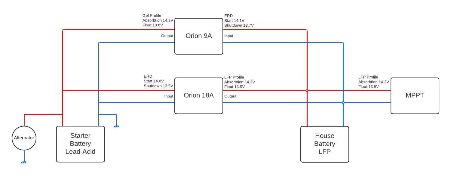
What i meant with “Voltage control wont work” is not that the Engine Running Detection will not switch on, but rather that it will switch on more than you want, and on both Orions at the same time. This is not about isolation or not, it works as good or bad using non-isolated Orions. I hope a little schematic makes things clearer
If the MPPT has sun, it will charge the house battery up to 14.2V. At 14.1V the 9A Orion will detect its “engine running”, so it will enable charging the starter battery. In this example up to 14.3V. However, the 18A Orion is set to 14.0V ERD, so it will in turn also enable its charging of the house battery.
This circle will settle at some power level, no real harm there. But the issue is, each conversion has its efficiency, so you will end up wasting energy. As soon as the MPPT has no sun anymore, the two Orions will drain both batteries by trying to charge eachothers, until the first battery falls below the ERD shutdown voltage.
Same situation when the alternator is supplying power.
This wont blow up, it works to a certain point, but its not a nice way
Edit: You use a 30A Orion not 18A, but the issue is the same. Also, please let me know how it ends up working, im curious to know if im wrong
Thank you very much for your effort! Okay, I understand the problem, but I still think that it might work reliably due to the chosen voltages. It will take a bit longer: the Orion has arrived (used), but unfortunately, I didn’t notice that it’s a regular Orion without the Smart features… My mistake, but that’s how it is now.
I haven’t implemented it yet because I’ve noticed I have a different problem. It’s not summer that’s the issue, but winter (i.e., the standby time). In summer, the car rarely sits long enough for the starter battery to discharge significantly. In winter, it’s different.
I’ve found a different solution: I’ve connected a permanent charger to the starter battery and adjusted the values in the built-in Victron DC/DC converter low enough so that it passes through during charging. This keeps both the starter battery and the auxiliary battery fully charged throughout the winter.
It would be nice if the DC/DC had a summer/winter switch where I could store 2 different charging settings, but I can live with that for now—there are only 3 values I need to readjust so that the DC only charges when the engine is running.