DC coupled charger inverter with DVCC

Hi,

I currently have an ESS setup with a Multiplus-II, Smartsolar and pylonthech batteries. As I have no interest in feeding back excess energy into the grid and particular oddities relating to the local grid setup (3 phase delta) and regulations, I want to change my setup to ‘off-grid’ but with grid backup.

To achieve this (and to comply with local regulations), I need to DC couple a charger with the DC bus. And the charger must not be able to act as an inverter.

Current setup: Grid => Multiplus => DC bus <= Batteries/Solar
Wanted setup: Grid => Charger => DC bus <= Multiplus/solar/batteries

The key point here is that charger is not, and cannot be an inverter. Ie, if I would use a multiplus as dedicated charger by setting the switch to ‘charger only’, I would still not comply with local reg.

So my question is:

  • Is there a victron charger that can be used in this situation. And i’m thinking about DVCC. Also the dedicated 48v chargers all seem to be stand-alone units
  • Or, is it possible to have a multiplus (or other) factory locked into charger mode (as that would be accepted by reg.)
  • Would it be possible to use a standalone charger in combination with smart batteries (BMS) if this charger cannot communicate with the battery. ( BMS is already connected to the cerbo), in terms of voltage, charge current, state of charge etc.

Thanks for your input!

Victron has no 48V charger that connects to a GX device.

In their standard configuration a multiplus has grid feed-in disabled. Further configuration options regarding feed-in are dependent on the chosen grid code. The grid code can be set only once. Maybe there is a grid code that complies, this would save you the trouble of installing a second inverter.

I don’t think so but it should not be necessary. You can set the correct charge voltages in the standalone charger and maybe control it with a relay output of your inverter or GX device (do you use a cerbo?). If you want to control charge/discharge current a smartshunt may be necessary.

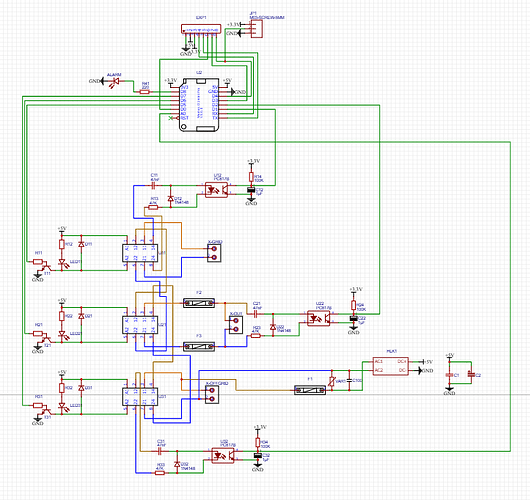
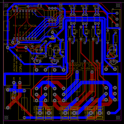
I use a ATS (automatic transfer switch) to provide backup power to my off-grid powered devices. A big disadvantage of using a charger is the sum of conversion losses. Your charger/BMS/battery/inverter all have between 2-20% losses that will add up as a sum of all losses in devices. The losses are significant during dark winter days when electricity prices are highest. Therefore I prefer to use an ATS. I built mine myself. They are mainly ESP32 controlled relais with AC-sesnsors based on optocouplers to measure voltages in between switching sequence steps. The are controlled by Node-Red to save the batteries lowest 20% charge.

Gerd, do you have a schematic of your setup (not the ats, but the whole thing).

Could you also elaborate on what is connected/disconnected with the ATS?

Thanks

I have page based schematics off segments but I can’ access them from here. But I will describe you the ATS implementation part.

An ATS has 2 inputs grid and offgrid, 1 output for loads, a wifi connection provided by the ESP to Node-red.

The ATS have redendant PSU’s (powered from both inputs)

My house installation has several breakers powered by 3 phases L1/L2/L3.

My offgrid plant contains 3 inverters but all offgrid so asynchronous from the grid.

1 Inverter is MP2 48/5000 the output is generating what I call phase L4. has its own RPI GX.

1 inverter is Phoenix 24/2000 the output is generating what I call phase L5. has its own RPI GX.

1 inverter is only a 24/500 and is only powering my Raspberry Pi’s running GX / internet modem / mesh acces point’s. So dedicated for communications.

This makes it possible to remotely update the inverters while powering the IT part with i dedicated inverter. The inverter also serves as a backup.

I built 6 MQTT controllable ATS and they are hooked up to loads I want to automate for summer / winter depending on battery SOC hysteresis

Those 6 are placed between the breakers and loads using the grid input / load output.

The offgrid inputs are connected trough 30mA / breakers to the L4 and L5 off grid inverters.

For non automated loads I used ATS switches that simply are factory made and use a priority/backup power selection for offgrid/grid.

They contain smaller loads like toilet single LED lighting, Doorbell power, basement lighting, and so on, things the system can handle even in the winter.

I hope I informed you enough. More questions,?just shoot.

Am I correct to understand, that you have a true off-grid installation. No charging from the grid. And in cases when there is insufficient off-grid power, you will transfer parts of the load with ATS’ to the grid, bypassing the off-grid installation?

In any case, this is something that could work for me, only I had hoped to be able to do grid charging, and make full use of dynamic pricing.

Thanks

That is correct.

The way I see dynamic pricing:

When prices are low there will be sun and i charge things myself.

When prices are high it is dark and it is better to consume the power directly trough an ATS without efficiency losses.

That way of thinking only applies if you have sufficient solar panels.

For people without solar panels that purely have DESS i can understand but they have to be aware that they are subjected to future formula/policy/pricing changes.

Kind Regards,

Gerd