Hello everyone,
I’m checking back in.
First of all: Thanks to Alex – the hint with the Little Endian format was the key!
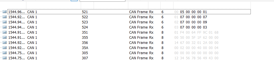
Now all values (voltage, current, SOC, cell_min, cell_max, Tmin, Tmax) are arriving correctly at the Cerbo.
It’s sufficient to send the 4 messages to keep the system “happy.”
void Send_BMS_0x351_DynamicCVL(uint16_t ccl_01A, uint16_t dcl_01A)
{
    CAN_TxHeaderTypeDef TxHeader = { .StdId = 0x351, .IDE = CAN_ID_STD, .RTR = CAN_RTR_DATA, .DLC = 8 };
    uint8_t TxData[8] = { 0 };
    uint32_t TxMailbox;

    extern int32_t u2;       // Systemspannung in mV
    extern int32_t current;  // Strom in mA (positiv = laden, negativ = entladen)
    extern bool cvl_reduced;
    extern uint32_t cvl_reduce_start;

    uint32_t now = HAL_GetTick();
    uint16_t cvl_01V;

    if (ccl == 0)
    {
        // Ladeverbot → Ladegrenze absenken
        if (!cvl_reduced)
        {
            cvl_reduce_start = now;
            cvl_reduced = true;
        }

        if ((int32_t)(now - cvl_reduce_start) < 10000)
        {
            // Für 10 s → ganz sperren
            cvl_01V = 0;
        }
        else
        {
            // Danach → Entladung weiterhin erlauben
            cvl_01V = (uint16_t)(u2 / 100); // Systemspannung in 0.1V
        }
    }
    else
    {
        // Laden erlaubt → hohe CVL für MPPT
        cvl_01V = 520;  // 52.0 V
        cvl_reduced = false;
    }

    // CVL
    TxData[0] = cvl_01V & 0xFF;
    TxData[1] = (cvl_01V >> 8) & 0xFF;

    // CCL
    TxData[2] = ccl_01A & 0xFF;
    TxData[3] = (ccl_01A >> 8) & 0xFF;

    // DCL
    TxData[4] = dcl_01A & 0xFF;
    TxData[5] = (dcl_01A >> 8) & 0xFF;

    // Discharge voltage (nicht genutzt)
    TxData[6] = 0;
    TxData[7] = 0;

    HAL_CAN_AddTxMessage(&hcan, &TxHeader, TxData, &TxMailbox);
}


void Send_BMS_0x355(void)
{
	CAN_TxHeaderTypeDef TxHeader = { .StdId = 0x355, .IDE = CAN_ID_STD, .RTR = CAN_RTR_DATA, .DLC = 8 };
	uint8_t TxData[8];
	uint32_t TxMailbox;

	uint16_t soh = 95;          // 95 % → ×1
	uint16_t soc_hr = 8044;     // 80.44 % → ×0.01

	TxData[0] = SOC & 0xFF;
	TxData[1] = SOC >> 8;
	TxData[2] = soh & 0xFF;
	TxData[3] = soh >> 8;
	TxData[4] = soc_hr & 0xFF;
	TxData[5] = soc_hr >> 8;
	TxData[6] = 0;
	TxData[7] = 0;

	HAL_CAN_AddTxMessage(&hcan, &TxHeader, TxData, &TxMailbox);
}

void Send_BMS_0x356(void)
{
	CAN_TxHeaderTypeDef TxHeader = { .StdId = 0x356, .IDE = CAN_ID_STD, .RTR = CAN_RTR_DATA, .DLC = 8 };
	uint8_t TxData[8];
	uint32_t TxMailbox;

	int16_t voltage = (int16_t) (u2 / 10);         // mV → 0.01 V
	int16_t current1 = (int16_t) (current / 100);  // mA → 0.1 A
	int16_t temp = (int16_t) (Tmax * 10.0f);       // °C → 0.1 °C

	TxData[0] = voltage & 0xFF;
	TxData[1] = voltage >> 8;
	TxData[2] = current1 & 0xFF;
	TxData[3] = current1 >> 8;
	TxData[4] = temp & 0xFF;
	TxData[5] = temp >> 8;
	TxData[6] = 0;
	TxData[7] = 0;

	HAL_CAN_AddTxMessage(&hcan, &TxHeader, TxData, &TxMailbox);
}

void Send_BMS_0x35A(void)
{
    CAN_TxHeaderTypeDef TxHeader = {
        .StdId = 0x35A,
        .IDE = CAN_ID_STD,
        .RTR = CAN_RTR_DATA,
        .DLC = 8
    };
    uint32_t TxMailbox;
    HAL_CAN_AddTxMessage(&hcan, &TxHeader, alarm_flags, &TxMailbox);
}


void Send_BMS_0x373(void)
{
	CAN_TxHeaderTypeDef TxHeader = { .StdId = 0x373, .IDE = CAN_ID_STD, .RTR = CAN_RTR_DATA, .DLC = 8 };
	uint8_t TxData[8];
	uint32_t TxMailbox;

	// Umrechnung Spannungen in mV
	uint16_t Zell_min_mV = (uint16_t) (Zell_min * 1000.0f);
	uint16_t Zell_max_mV = (uint16_t) (Zell_max * 1000.0f);

	// Umrechnung Temperaturen in Kelvin (ganzzahlig)
	uint16_t Tmin_K = (uint16_t) (Tmin + 273.15f);
	uint16_t Tmax_K = (uint16_t) (Tmax + 273.15f);

	// Zellspannung min
	TxData[0] = Zell_min_mV & 0xFF;
	TxData[1] = Zell_min_mV >> 8;

	// Zellspannung max
	TxData[2] = Zell_max_mV & 0xFF;
	TxData[3] = Zell_max_mV >> 8;

	// Temperatur min
	TxData[4] = Tmin_K & 0xFF;
	TxData[5] = Tmin_K >> 8;

	// Temperatur max
	TxData[6] = Tmax_K & 0xFF;
	TxData[7] = Tmax_K >> 8;

	HAL_CAN_AddTxMessage(&hcan, &TxHeader, TxData, &TxMailbox);
}
Message 0x351 is a bit confusing, and that’s exactly where I’m stuck right now.
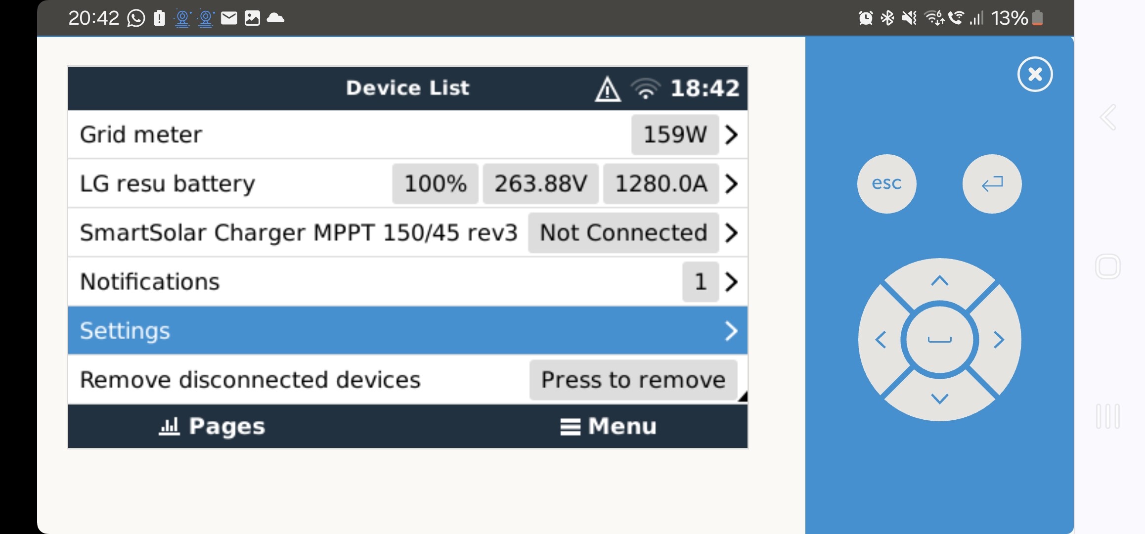
In addition to the Cerbo GX, the Multi, and the DIY battery, I also have an MPPT 150/45 in the system.
I’m using a Li-ion battery (12s). This means I have a voltage range of 36–50 V, and here’s the issue:
If I want to discharge at full power, I have to set the CVL value (which is actually supposed to be the charge voltage limit…) to the current battery voltage or slightly below. The MultiPlus uses this value to regulate discharge current and increasingly limits it as battery voltage drops.
If I set CVL to 52 V, I can only discharge at max 7 A at 42 V → not good.
Solution: I lower the CVL value — but then the MPPT “thinks” that the target charge voltage has already been reached and stops charging → also not good.
Its written down in the “Victron CAN-bus BMS Protocol” application note, point 1.5.3.
Either I’ve misunderstood something, or the Victron ecosystem is more tailored to LiFePO4 cells, which have a much narrower voltage range.
DVCC is enabled for voltage and current. All values are provided by the BMS.
Is this normal? Is it supposed to work like this? Or is it possible to use Byte 6&7 of 0x351 for discharge voltage?
Is there any meaningful setting or workaround?
Is there a way to export the whole setup so someone with more experience can have a look?
Paul