Built this little setup to run my pool pump (working really well) but I think it could be improved to stop the controller from trying to charge the battery bank at 99% The solar panels make just a bit more or just a bit less than the 430watts my pump needs This works well but causes the charging to constantly bounce between charging and idle when production is right at that level. I’ve read I could change some settings and stop the charging function until the battery reaches 90% I think this is hysteresis ? (Don’t charge till 90% and then only charge to 98%) Is this possible with my current setup? My gear is 100/50 controller, cerbo gx, smart-shunt, 5 200w panels and 4 200ah batteries. Thanks in advance for any suggestions.

hi Roy!
as far as I know (and by now I learned a lot…) there is no “buit-in Victron way” to limit charging to a certain SoC. BUT you have everything to do that perfectly as ever you like.
You just need to run a minimal script on the cerbo which controls the charge target voltage by setting the DVCC Maximum chrage voltage depending on the SoC info of the SmartShunt.
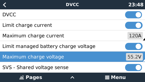
When I want the system to charge the battery, I set the max charge voltage to bulk level, when I don’t want it to charge further, I set it to float voltage. The MPPT chargers drive the loads then but SoC is kept steady (does not bounce…).
Since this setting is a limitation, you need to adjust the bulk voltage of the MPPT charger slightly higher, e.g. +0.1V. Since that never gets reached, the MPPT does not switch to float, so you’re fine.
If you run the script (e.g. Python) on the Cerbo, you can read the SoC directly from the dbus and write the charge voltage limit to the dbus. This is quite simple.
I’m runing that script on an external Raspi, so I’m utilizing MQTT to read and write the values, but I have some sample scripts on how to access dbus, also (and there are many on the inet). If you are not familiar how to do I could help you.
greetings!
Phil
ps. my script looks like that:
while True:
    soc = get_soc()
    if soc > 85.0 and voltage_is_high:
        set_voltage_limit(float_voltage)
        voltage_is_high = False
    elif soc < 84.5 and not voltage_is_high:
        set_voltage_limit(bulk_voltage)
        voltage_is_high = True
    time.sleep(30)
by the way - are you situated in Australia or somewhere the sun always shines? 1000Wp PV (700..750W charger capability @“12V”) with over 10kWh battery capacity is a little bit ‘uncommon’.
with your 450W pump load there are only 300W left to charge the accu - it will take about 35 hours to charge if the battery is empty. Or isn’t the pump running continuously?
I use node red to control charging. This is a flow I use to drop the charge current based on voltage. SOC is too unreliable and voltage is king. What this flow does is adjust DVCC as the voltage rises. Depending where you set the limits this will allow the battery to charge to 99% before setting the current to 0. As the voltage drops the allowable charge current will increase. You can adjust the range where you want to start reducing the current to get the desired response from the system. All you need to do is change the nodes and input the voltage from the system either the MPPT voltage or shunt voltage.
ADJUST DVCC ON VOLTAGE 12V.txt (7.3 KB)
The dvcc charge voltage only applies when using managed batteries.

We discussed this internally a while back.
It is completely unsupported to use it with unmanaged batteries, it was also confirmed that it did not work for unmanaged batteries.
Victron has been clear this is a setting for temporary use to assist with specific batteries (BYD/Pylon) that can have balancing issues when new, so we really do not want to encourage its use on an ongoing basis, so anyone doing so, does at their own risk.
In your example you appear to have a managed battery but have chosen to ignore it for management.
The parameter overrides CVL, without a BMS physically connected there is no CVL and no external control of the chargers by the BMS, DVCC reverts to the inverter/charger algo and CVL should not override that in this instance.
Maybe it has changed recently, but that was the consensus at the time. There was a reason it was called “Limit managed battery charge voltage”.
I am running Node-RED on a demo Venus OS I don’t want to mess up my live systems. All the flow does is reduce the charging current. There is no controlling BMS, and the charge voltage will be set in the MPPT. There is no Multiplus in this system. All the function does is output a lower current based on the battery voltage. Instead of using DVCC, you could just adjust the max charge current of the MPPT, but I’m not sure if they go down to 0A. I’ll have to have a look tomorrow when the sun’s up. You could also disable the charger based on SOC. I’ll write a function for that tomorrow
Thanks for this, I need to do a bit more reading to fully understand the implications and requirements. It seems like a feature that would be often required.
My setup does seem a bit unusual perhaps as I want to use it to back up my sump pump when the pool is not in use. I’m near Buffalo NY so we get decent sun in the summer and not that much in winter, hence the over sizing. It’s 12v now but I intend to install a multiplus unit this fall and switch over to 24v. I have 8 panels, but right now I have 1 catching morning sun exclusively to help restore the batteries until the pool kicks on at noon each day and then 4 panels in the sun for the afternoon when I want to pool running. If this all works as expected I’ll add another panel to each set (2+6). Perhaps a super simple way to achieve this until I install the multiplus is to run the pump in the AM to draw down battery level in the AM and then let it work to run pump and recharging without the chance it bouncing all afternoon. Really appreciate the info, lots of reading to do on my end as I learn more.
Just ordered a raspberry pi to run a few functions - including node-red as I have a lot of home automation stuff going on as well. Thank you for this flow.
You don’t need a Pi. You can install Venus OS Large and Node-RED will run directly on the Cerbo GX. I do run a couple of Pi’s instead of the Cerbo, but I also have another one with Venus OS on there for testing code before I put it on a live system.
This is what it looks like on my system. I have the scale node set to decrease the charge current above 13.6V. What this does is allow the system finish off the bulk charge without tripping a BMS or hitting the absobtion stage 1-2 hours before the battery is ready to start absorbtion. I dont know why this is not a feature already. I understand your pain and you could tune it so you dont even hit absorbtion and just remain in a bulk stage with a max voltage. As your system draws down the battery the current will ramp up.
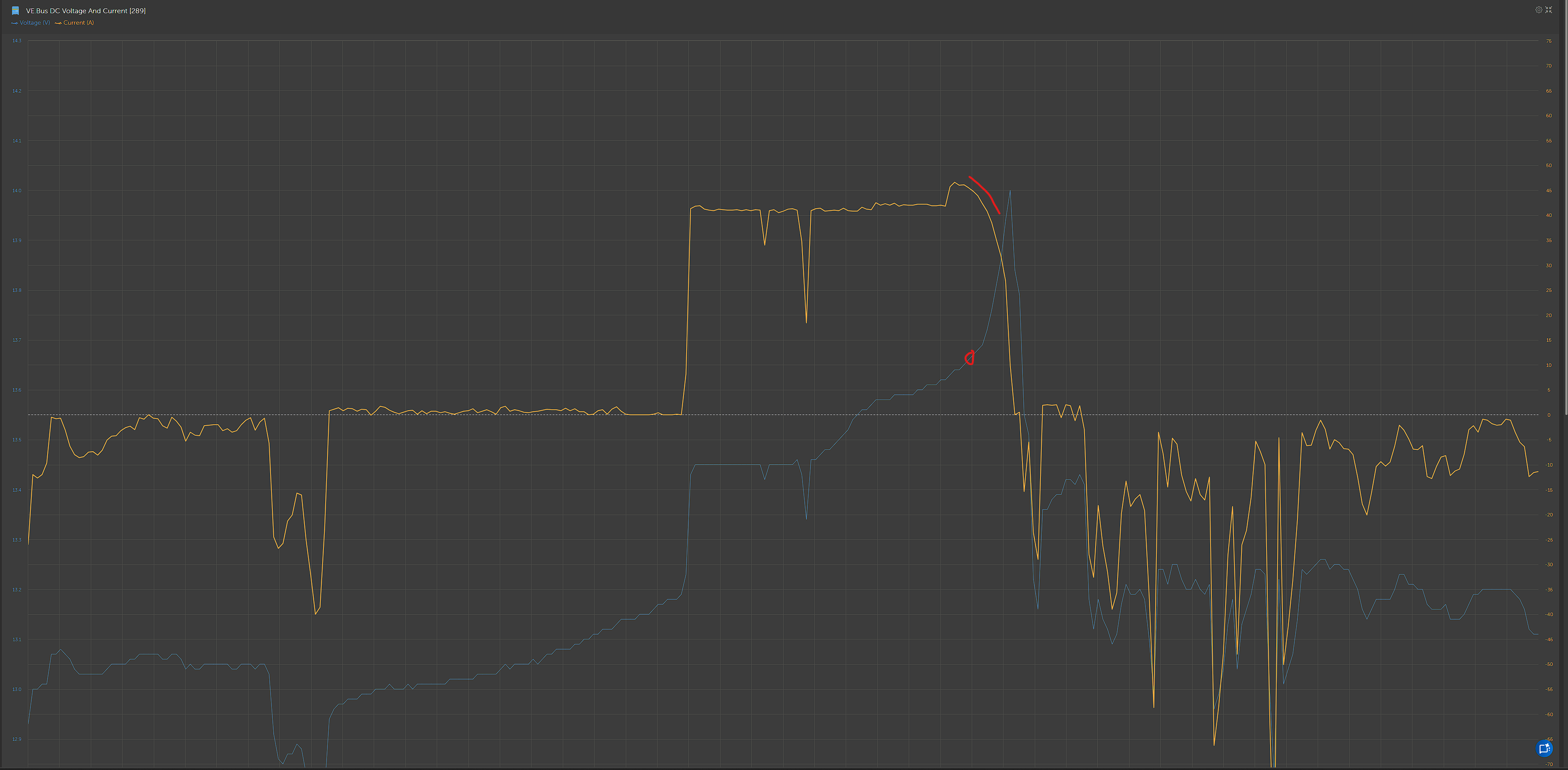
The sun’s up, I put a little system together. It works really well. I have a 100/20 and an inverter with about 100W of load. I have limited the charge current to 10A max with DVCC in the function just for testing. When I take the inverter load off, the voltage rises and the charge current is reduced, stopping the MPPT going into absorbtion and remaining in bulk. I have the MPPT absorption voltage set to 14.6V, so it won’t hit it. I also made a few tweaks to the code that were needed.
System breakdown, Venus OS large with Node Red running. MPPT 100/20 provides the voltage, a 600W inverter for the load.
Most update code in the lower post.
I made a few adjustments after doing some research. DVCC is, by design, a bit sluggish to respond. To work around this, I added code to smooth the changes, giving the system time to adjust.
I also added a node that monitors battery voltage and disables the charger if it goes over 14.2 V, then automatically re-enables it when the voltage drops back down. This way, if there’s an overshoot, it doesn’t have to wait for DVCC to react.
This is something I’ve wanted to improve for a long time, so it’s been a good deep dive. I also linked the SmartShunt to the MPPT so the current readings are accurate and not just a stale-data problem.
I just made an edit to V3. It’s smooth now. In the video, I apply a load of 10A to the inverter. The shunt measures the battery. Any load applied is matched by the MPPT with this algorithm up to 20A.
Nice to do a longer video, but it will hold 14V after the load is removed. The load is 150W, the MPPT is maxed out can deliver the full 20A, only supplying the loads. I turn the load off, and you can see the current go to 0. I have it set to 14V, but you can set it to anywhere you wan,t and it will not hit absorption or float and use every bit of solar. If you want to set it to 13.6V, you can.
You can run a balance charge when you need to.
DVCC 12V ADJUST LIVE SYSTEM V3.txt (16.1 KB)
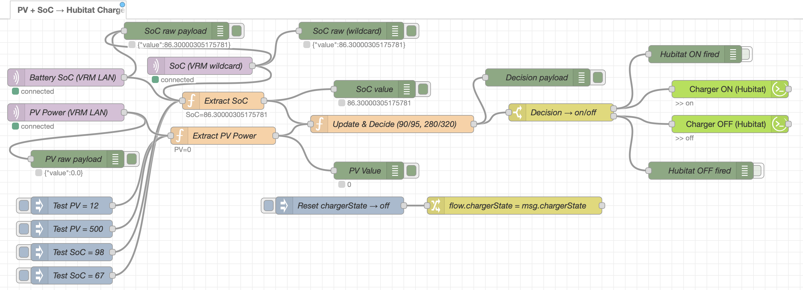
Owen - thank you for the work here, I’m starting to get into Node-red. You’re clearly lightyears ahead of my knowledge but you inspired me to learn more. I can see why having a test environment is a must, can I build a simulation of my actual setup on another platform such as pi? I made this flow after lots of trial and error and assistance from ai. This flow monitors SoC and PV so that when they drop below a threshold, it talks to a Hubitat controlled switch to turn on / off a battery charger. If solar production jumps up or SoC goes above threshold the charger is turned off. There is still a good chance that on a sunny day I’ll have the bounce problem, which with your examples I can mitigate. This was more of learning project, as I wanted to try integrating another system asI have an extensive home automation setup. Now I’ll try to integrate both. There is a significant amount of optimization I need to do and then I’ll clean it up - it’s messy but functional. I’ve got a more optimized flow, with some enhancements, but it took so long to get this working I’m wanting to test it in a non-production environment first - this is my first experience working with json, so feel free to chuckle at my kindergarten level work.
You can put Venus OS Large on a Pi and use Node Red. You can’t build a virtual system, but you can load the demo modes so you get some Victron gear to test some of the nodes like chargers, shunt multiplus, etc. Once you start Node Red, you can’t stop.
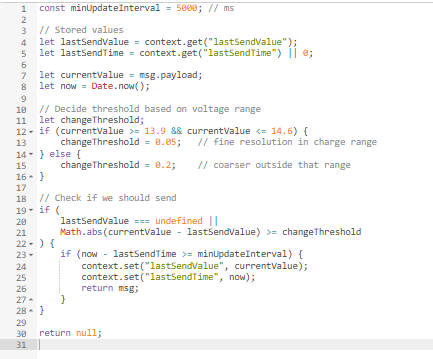
I did make a small change to this flow I added a slightly higher precision when the voltage gets higher. I find the 12V battery will spend 95% at 13.6V, but above that, it does not change enough to kick the charger back in, letting it go from 14V to 13.7V before kicking back in.
The hard part is looking at the load on the CPU and trying not to write values too often.