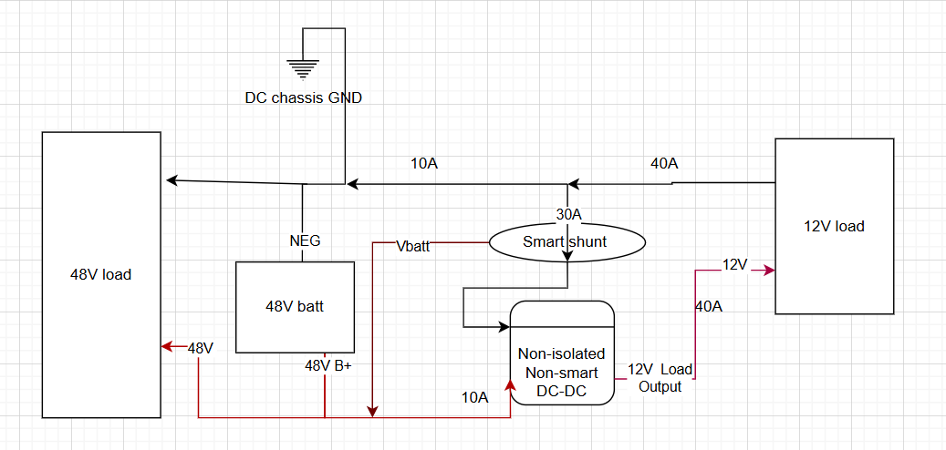
I want to use a smartshunt to monitor a non-isolated DC DC. Because its non-isolated, we know the current on the shared negative will be the difference between that on the input and output positives. We know the ratio between the input and output voltages. Therefore , mathematically, we can predict what the current should be on the shared negative , going through smart shunt in the below diagram.
e.g if its a 48v to 12v DC-DC, input current 10 amps , output current 40 amps, the shared negative should be at 30 amps (ignoring conversion loss).
If we can then tell the smartshunt to “divide its measured current by 3” before reporting it to cerbo (it’d be operating as an DC energy meter) then we have an approximately correct answer in Cerbo for the power input to the DC-DC (10 amps). Good enough for this application. By changing the shunt value in software to 3x less than what it actually is, it should be feasible to do this.
Question1 : the shunt value on BMV can be changed in software. The shunt value on SmartShunt can not. But I would assume it must be hardcoded in there somewhere as the BMV and Smartshunt are almost identical menus. Is it possible for it to be exposed, some hidden software setting?
Question2: Any way to mathematically operate on the value after its inside Cerbo? I have looked around in NodeRed, can do maths there of course, but there doesn’t seem to be a way to do it before it shows as a device in Cerbo.
Question 3: any chance victron will release a high-side version of smartshunt?
other points:I have already researched high-side shunt monitoring: It doesn’t work with a victron smart shunt. Other brands of smartshunts that are suitable for high-side, don’t work with victron so getting the data into victron becomes hard. Likewise other monitoring techniques like hall effect sensor. any “I did this already and here is how I did it” would be great.