Hi all, I am having an issue with this diy install.
The product is multiplus ii, connected to the grid via AC input only. I want it to supply the load from the batteries (no pv) to cover the house consumption, no export, no being off grid. From what I understand this should be achievable under my setup.
Multiplus has been set up with ve configure as UK country, and ess assistant has been installed.
It is managed by the raspberry pi via mk3, ct readings are provisioned from MQTT. Battery is jk bms.
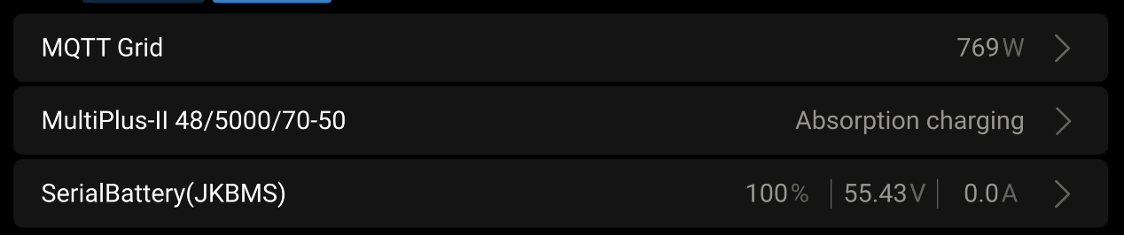
System charges the battery with no issue, however, under any combination of settings (ON, Inverter only), there is a supply from the inverter. I feel like there is something very obvious which I am missing, so please help me
Silly question is the multiplus switch in the correct position? What is providing the grid reading? May need a proper solution ie the Victron cable CT the VM one or the ET112 or the other one to integrate directly and insure no issues with the integration ie the spoof could be the issue
5.1. On/Off/Charger only Switch
The switch is located on the underside to the bottom right of the product.
The switch has three positions. The centre position 0 is Off. The I position is On, and the II position is Charger Only.
When switched to ‘I / On’ (rocked towards the front of the unit), the product will come into operation and the inverter is fully functional.
Hi,
your settings look ok from what you showed. It’s quite unusual that there is no current from battery to MP2. I assume you have some sort of fuse between the DC-input of your MP2 and your battery. What sort of fuse is that? Can you measure a voltage difference (yes voltage, not resistance) between fuse input and output? If so, the problem might be the fuse.
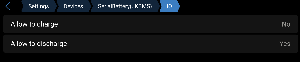
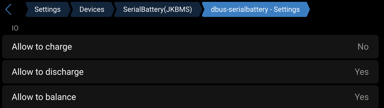
btw, how has your battery been charged? Your bms settings do not allow charging
not silly at all. It was indeed set in the position 2 DOH
I have completely forgotten about it and was concentrating on the software side of things. It has switched into the inverter mode, and while some settings are still wrong, at least its inverting now. I can work with it
@strombreite no idea )) this was not the first day I have been struggling with it, so probably it was a different iteration of settings (I am assuming you are referring to the Inverter only?)
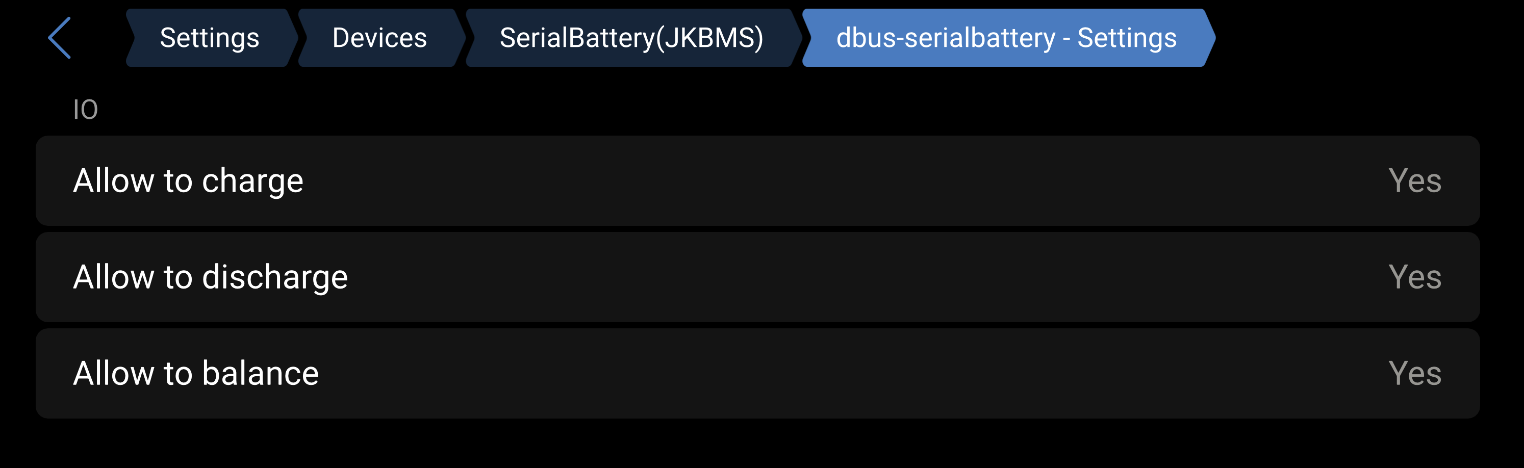
Well, from my own struggling with serialbattery I remember that you can set the limits for discharge current in both the serialbyttery config and the bms itself. The one in the bms is the actually limiting one.
How did you connect the bms to the Pi? RS485, Modbus, bluetooth…
Turns out it was even sillier for some reason. In inverter only it was limiting to 40w, once I flipped to ON it went full throttle.
Live and learn. For now I will keep it in on with scheduled charging for the night in ess until I fine tune eveyrhing (need to turn. off the charging when the car is charging as well, fun staff).
Thanks for all help guys, appreciate.
P.s. rs485, with jk bms v19 bluetooth was not working properly for some reason.