I am looking for an adjustable output voltage MPPT solar charge controller. I have LFP power packs that have a rated voltage of 41.6 volts (13 cells at 3.2V). I need an MPPT solar charge controller capable of handling an input from my two 400W solar panels in parallel Pmpp 400W, Isc 11.14A, Voc 45.30V, Impp 10.77A, Vmpp 37.13V, Vsys 1000V with an output charge voltage capable of being set to 46.8V. Can any MPPT solar charge controller on the market fit my needs? When I asked AI this question it pointed to the MPPT controllers Victron SmartSolar MPPT. The power packs are all in parallel. I am new to this so be kind.
You will need to rewire your modules in series to use a Victron MPPT charge controller. The minimum start voltage from the modules needs to be 5V greater than the battery voltage.
The 3.2V seems to be a fairly low voltage, most LiFePO4 run from 2.5V/cell flat to 3.65V/cell at 100%. 3.55/cell which is a good nominal for max V, gives you 46.15V, which all but the smallest MPPT’s can cope with. 13 cells is an odd number, most packs use 15 or 16 cells in series.
800W @ 46V gives ~17A, so the SmartSolar MPPT 100/20 (up to 48V) would suit this requirement.
The 100/20 MPPT is what you want. It does charge 36V batteries with a firmware update. It will have a 36V profile for 12S, 3.65V cells, 43.8V max charge 38.4V nominal at 3.2V. You should be able to adjust the voltage for your battery. At 3.2V, yours might be LTO chemistry. You will also have to series connect the panels. They are not voltage matched and the charger will not start unless you are +5V above the battery voltage.
7-7-2025 Victron energy chat.pdf (381.8 KB)
Take a look at the attached which shows a picture of my system an a little more about what I am trying to d. I have six 400W 48V panels in my backyard.
I just need something to charge the power packs because the 400W maximum input is each head unit is just not enough.
I am going to attach the power pack manual so you can see what I have. I think the manual and the picture in my PDF will give you a good idea of what I have.
Power Pack +1000 EN.pdf (2.3 MB)
I tried to attach the head manual, but it would not let me.
Thanks, Genmann
Genmann
Zero E head EN.pdf (4.6 MB)
Here is the manual for the head unit.
Genmann
The 100/20 will work. The input you want to use is rated for 20A. If you set it to 36V and adjust the voltages for a 13S to match the battery. Here you can see the demo for the Victron app.
You will have to series connect the panels Voc 45.30V, Vmpp 37.13V. You will need 41.6V + 5V to start charging, so 45.3V is too low. If you series connect them, you will get just over 90V and 74.26Vpp. That will give you about 800W in 74.26V x 10.7A.


Owen, I think I am starting to understand what your talking about. What do you mean when you say: Adjust to voltages for a 13S to match the battery? I can connect two panels in series. Can you give me the complete description of the Victron 100/20 your recommending?
Is there some type of wiring diagram for two panels connected in series connected to the Victron 100/20 your recommending? I see some listed as Smart solar controllers and some not, can you explain the difference?
I am excited that there is a product that will work! Now I just need to better understand how it is all wired and how it works with my power packs.
Genmann
You have a 13S battery. The standard 36V is 12S, so you have a higher voltage. Download the Victron Connect app, and you can see what settings you can put in using demo mode, like I have.
There really are no diagrams. I have done this sketch. The voltage needs to be below 100V when you connect the panels. The smart has Bluetooth built in; this is the one you want.

Owen, I received my MPPT 100 / 20 SmartSolar charge controller.
Now I understand the wiring you show no problem, but I want to make sure I don’t have issues by hooking up in the wrong order or having a configuration issue.
My power packs have a XT60 input that is finger safe and has no voltage at the two terminals when nothing is plugged into the power pack.
With the current FIRMAN MPPT 400W rated controller (that I am removing to use Victron) you hook up one 400W panel to the MPPT and the output XT60 reads about 46 volts during the day.
When you plug in the FIRMAN MPPT XT60 into the power pack you hear a relay click and then the current is allowed to charge the power pack. So I need the Victron XT60 output to be live to get the power pack relay to pickup and allow charging current to the power pack batteries. The Victron will not see any power pack battery voltage until that internal power pack relay closes.
Before I go any further I want to make sure the Victron MPPT will have voltage at the XT60 allowing the battery pack internal charging relay to close.
I am hoping your answer is YES!
I was reading the manual and I think it says to connect the battery (my case XT60) to the Victron controller and let the controller automatically pick the battery voltage. But I also believe I read that if you connect the PV to the controller first it defaults to 12V batteries. This is all new to me. I just want to make sure I don’t destroy the Victron SmartSolar charge controller.
Anything will help.
Thanks, genmann
There are a couple of things you can do.
The MPPT will tolerate being hooked to the panels for a short time. It will turn on when the sun hits the panel in the morning and output the absorption voltage. You will need to check what the relay does when the battery is full. If it opens, you may have a problem where the MPPT is at full solar for long periods.
Ideally, you would want another battery before the tower. I would look at setting up a 3S 12V AGM battery, 20AH. It will be able to produce 1C or 20A to the input. The AGM will charge to 14.9V EA or a pack voltage of 44.7V. All you will need to do is hook them up and set the MPPT to 36V. On the output from the battery, use a battery protect and set it to disconnect at 13.6Vx3 40.8V. This will keep the AGM full.
The other option is to set up a capacitor bank using 3S 16V-83F Farad Capacitor Super Capacitor 2.7V-500F, for example. You will need to be extremely careful you do not overcharge them, so you will still need a battery protect on the input.
You will have to do some experimenting to see how everything works.
Owen, I don’t think the relay opens when the battery is full. I can recall removing the XT-60 when the pack was at full capacity using the FIRMAN MPPT solar controller and I recall hearing the relay click (open). Each time I plug in the XT-60 the relay clicks and the head unit shows the wattage going into the battery stack.
So I want to understand the steps to test the relay.
- Do I try to do any configuration prior to wiring up?
What is the order of the next steps?
For example- Do I first connect the panels in series and connect them to the Victron MPPT?
Next- do I connect the XT-60 wires to the MPPT
Lastly, do I plug in the XT-60 into one of the power packs of the stack?
What should I look for? How long can I keep it connected.
I really appreciate your help.
If you can make a step by step list to help determine how the relay functions.
Thanks, genmann
You could power the MPPT up using the power supply AC-DC charger that you have, or connect any battery with a voltage up to 48V. Without any solar connected put these settings in like I posted previously.
You can plug the XT60 into the battery tower, then turn on the solar and see how it works.
If 48.6V is too high and the tower goes into over-voltage protection, you may need to lower it, 45V for example.

Owen, I really appreciate your help. I don’t have a AC-DC charger - my FIRMAN MPPT solar controllers hook up to the solar panel DC output and then to the power pack.
I do have a 12V AGM battery. Are you saying to hook up my 12V battery to the solar input on the Victron solar charger or to the batt connections on the Victron solar charger?
I am hoping that at some point I can somehow connect my phone to the Victron solar charger.
Now at this time I can only see the DEMO screen and there is no 36V selection, just 12V and 24V.
At some point do I get connected to my Victron solar charge controller and move to a screen where I put in the values you posted? Can I put those values into my Victron solar charger without actually being bluetooth connected to the Victron?
Any ideas are welcome.
Thanks, genmann
Use the mppt calculator to be sure that your 90ish V won’t get too near the 100V limit for a 100/20 in colder weather.
It’s not worth the risk.
Just hook it up to a 12V battery without solar if you have one and change the settings. There will be 12V, 24V, 36V, and 48V options for the 100/20 you might need an update to the firmware. Choose 36V and adjust the voltage to match your 13S battery. Most 36V systems are 12S, so you have a slightly higher voltage. But you also need to test what you can input without exceeding the voltage limit on the tower’s input.
Owen, well I set two Victron 100/20 solar chargers up just like you said and hooked two panels in series and both worked to charge the stacks.
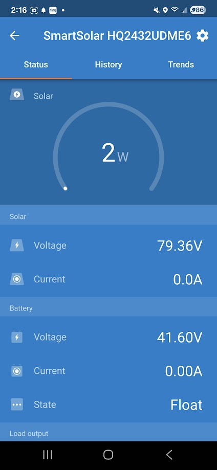
Now they are on float with no power because the stacks are full.
With Float at 41.6V when will the Victron chargers kick back in?
Now in each head unit I have an EC5 connection and one of the same solar panels plugged into it.
I have 6 solar panels in total. Two in parallel feeding a Victron and going into one power pack in one of the stacks. I also have the same thing feeding the other stack. Three panels go into each stack and the two stacks outlets are paralleled together.
Now the EC5 is putting in about 60W into each of the head units now and each stack is about 97% full. The Victrons are in float mode and not putting anything into the power packs on either stack.
The Victrons BATT has the float voltage at the XT60 connectors, but no current is flowing.
When will the Victrons start charging the stacks?
I put more load on the stacks to see if I can draw down the stored power, currently at 97%. I think the stacks were at 100% before I added more load and the sun is starting to go down.
Both stacks started in Bulk mode and I had to leave, when I got back both Victrons were in float mode with the stacks, I think one said 100% and the other like 99%.
I am just letting them run and see as the batteries discharge, will the Victron MPPT solar chargers kick back in?
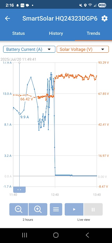
The voltage peaked at about 83V at one point. for each Victron. 81.77V now when in Float and stacks around 97%
I put one Victron in one stack yesterday and the other Victron today.
I had no faults show up on the head unit and it all appeared to charge up okay.
Each head unit has a MPPT solar charge controller in it along with a 3000W inverter.
Checking the SmartSolar app the float voltage is in the status is 41V. 40.93V ish
My main concern will the Victron MPPT solar chargers start charging again when the stack loses some of its stored energy?
I recall something about 5V above the battery voltage, but I am not sure where I got that.
Your thoughts would be appreciated.
genmann
You might be able to ignore the float voltage and set everything to 46.8V. Bulk, ABS and float all the same 46.8V. It’s not clear how the input works. It might have its own MPPT and not be connected to the battery. The Victron MPPT is not necessarily a charger; it just supplies the regulated voltage to the input. Everything seems to be working. The best thing about Victron gear is that you can get it to do whatever you want.
You also might want to try dropping the voltage down a little. You dont need to be at the max input voltage. Try half a volt and see how it performs.
Also it seems to be working fine you have done a good job.
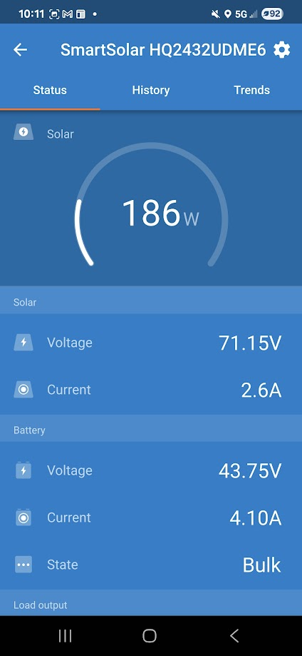
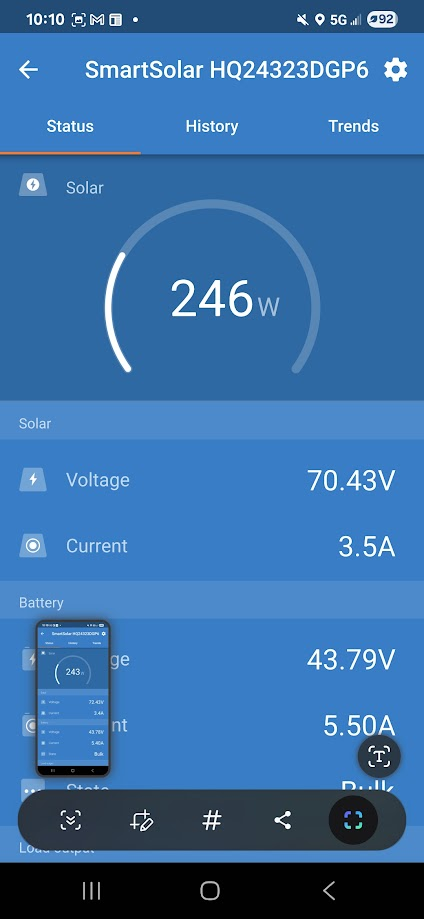
Owen, today when I got home both MPPT controllers were in Bulk mode and working fine. I did nothing with changing any settings. We got a nice sunny day.
I will watch what I have and see if I need to change anything in the future.
I will keep you posted.
Thanks, genmann
That’s a good idea if you tweak anything, post it. Someone else might be interested in solving the same problem.
Understood. Thanks for your help.