LiFePO4 battery config for UPS purposes

Hello All,

There is a situation where an MP2-3K is used together with a 16S 5kW LiFePO4 battery for providing UPS services in the rare occasions of grid failure.
The battery is charged up to 56.24 V in order for the battery to reach above 56V (3.5V per cell) and balance properly.
So the absorption voltage is set to 56.24V and is kept for 2 hours, time during which the battery balance nicely at no more than 10mV difference between cells.

In this moment, with the use of the Virtual Switch AC input ignore feature, the system is set to charge to 100% SOC with about 0.15C and then to slowly discharge to 30% SOC.
Based on consumption, the cycle is repeating at about 3 days. Charging 6 hours, absorption 2 hours, 72 hours discharge.
But if a grid failure is happening when the system is at a low SOC (e.g. 40% SOC), then the backup time is quite short.

Now the interesting part…

I was thinking to set the float voltage to about 53.12V (3.32V per cell) in order for the battery to indefinitively keep a stable state of about 85% SOC and be ready enough to provide power for short emergencies.
Because the MP2-3K charger section in the VE configure doesn’t provide for LiFePO4 batteries things like storage voltage and re-bulk voltage, how the system will behave in this situation?
Will it enter storage mode or not during the waiting periods between grid failures? If yes, at which voltage? Is there a storage voltage setting for LiFePO4 batteries, that can be modified?
Will it enter re-bulk mode? If yes, when? Because reabsoption can be set, both as period and duration, but re-bulk no…

I believe that keeping this way at about 85% SOC is better, because it can provide longer back-up power if grid fails.
Also, the 85% SOC is quite a conservative SOC and keeping the battery for longer periods at these voltages/SOC is not hurting the battery.

I want to keep the system as clean and lean as possible, so no ESS assistants and no Node-Red solutions, please.

Thanks in advance for any opinions!
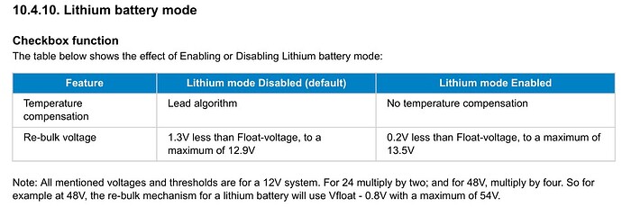
Now I’ve seen on the “VC configuration guide for VE.Bus products”, that the re-bulk voltage for 48V Lithium batteries is hardcoded at 0.8V below float voltage. Can somebody confirm this in the case of MP2 devices, without any assistant installed (e.g.ESS) ?

Quite scattered information among various docs…
Maybe the above/below wont hurt to be introduced in the Multiplus 2 manual too, because it’s a VE configure option…

Because when you try context help for Lithium batteries on the Charger tab on an up to date VE. Configure 3, the following happens.


My observation from my battery, is that my cells floated at 3.3375v will no longer accept charge.
And will have a Soc that will hover around 98%.


Given that my battery is charged by solar, and is fully charged better than every second day, my absorp time is low.
My battery also experiences 120 days a year that the temp is 35c plus.

My BMV is dialed in, pretty accurate for a month or so.

Thanks for sharing your experience.
3.375 or 3.325?
From your graphs, 13.3V / 4 = 3.325V

Batt voltage @ float = 13.35v.
Suits my 6 1/2 year old cells, with my use profile.

Modern cells might be different!
zzz.

Thanks for clarification. :+1:
Did you tried a capacity test now, after 6.5 years, to know the real state of the cells after submitting them to your “treatment”? :slight_smile:

Alex, this is solved in new BMS firmware using timers for different charging modes. I previously shared a new BMS operation algorithm. Huge thanks to Andy, he put the squeeze on JK.
The only drawback is that the timers have a limited time, but they will work cyclically, comparing the current voltage with the settings.

I was asking from the MultiPlus 2 perspective, if it will enter storage or re-bulk mode…
But now, on the test system, more than 24 hours and no storage mode with the lithium mode checked.
As per re-bulk, the second message in this thread seems to have the answer. It will also be tested.

Oh, unfortunately I don’t have such installations with long-term storage. I can’t check. Everything is in a cycle. And if I’m not mistaken, using BMS CAN + ESS + DVCC, the settings in the Victron Charger configuration for LiFePo4 with a fixed curve are ignored.
Correct me if I’m wrong.

No, you’re perfectly right.
The test system now has DVCC and BMS control disabled.
Of course after carefully study of previous cycles and their voltages for proper setting them into the MP2 charger section.
The great loss is the automatic charging voltage “tuning” near the top end, based on max cell voltage, but, maybe one day, I will write my own script to do exactly what I want: modify the charging/float/re-bulk voltages dynamically, based on conditions, at the script level.
Many will say, use Node-Red, but no, no additional overhead for the system for something that can be done in a couple of dozen script lines and anyway, it’s particular to my case.