I’d like to run these tests again over the weekend.
It worked three months ago during a test and also during a grid outage.
But now, with this nearby lightning strike, it didn’t.
Which transfer switch are you using?
I’d like to run these tests again over the weekend.
It worked three months ago during a test and also during a grid outage.
But now, with this nearby lightning strike, it didn’t.
Which transfer switch are you using?
The transfer switch on the ac out side of the multi’s, @BjoernK did say something about taking one rcd out I’m not sure how your regs are but not having as many RCD’s would make it less susceptible to nuisance tripping.
I imagine it’s due to the lighting and testing was all done from the switch rather than the ac in rcd trip? Try it with the RCD test function and see how the system behaves with that
Be careful as I see an EV charger down the line ultimately that needs a type B protecting against higher DC leakage not sure what else is protected by that RCD ie heat pump, not knowing the regs I’ll refrain from answering that question as it’s too dependent on a lot of parts ie what else that RCD protects and your regs.
Typ B is only needed for DC residual currents. As the Multiplus has a transformer, a DC residual current is not possible.
Don’t know the rest of your PV system, but either for the Multiplus nor for the grid you don’t need a B-Type RCD.
To your problem:
When the system worked before, also in a grid outage situation (as you said), then most probably something went broken thorugh the lightning. We all know, that such an event can produce various problems with different effects.
Do you have an Surge Protection Device? What is the status of this SPD? Did it trip? This could cause a RCD to disconnect.
Edit: I see this yellow component, but inside it look only like a terminal block… is this the SPD?
I don’t have an SPD in my installation.
There is a thermal heat pump present in the critical loads.
Only the RCD on the grid side, which is a Type A, had tripped.
After restarting the system, I first switched the RCD back on, then toggled the transfer switch — and everything started working again.
The question remains: why didn’t my critical loads receive power?
That yellow component you see is just a cable distributor.
Don’t know where you are located and if a SPD is not required by regulations, but anyway it would be usefull to be better protected.
Regarding your problem, - Why did you say, or how did you recognize, that the MP2 are pushing still energy to the “system”. You did not answer the question from Björn to that. If there is no grid available, and the MP2 are still generating 12kW, then it is only possible on the AC_Out side, this must be then your critical loads.
But I have an other idea, - as you say the system is now running again, why don’t you try to just disconnect the grid to simulate a grid outage and to check if the system behaves as you expect?
If it does what you expect, then it maybe was a side effect of the lightning strike. If not, then you better can analyse what is going on and with our help we can better identify what is wrong.
I’m located in Flanders, Belgium.
The reason I assumed the units were still trying to deliver power was because of the sound they were making.
I didn’t check the indicator lights to see if the inverter was actually on — that was my mistake.
I’m planning to perform that grid disconnection simulation over the weekend, when I have a bit more time.
I prefer doing these tests early in the day so the system isn’t under heavy load.
Thanks again for your support!
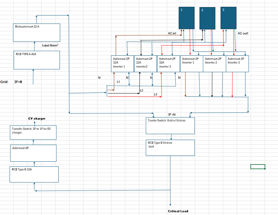
I ran a few checks: 1) When I disconnect the grid using the main switch in the grid cabinet, everything works normally — the backup activates. 2)But when I turn off the RCD, which also tripped during the lightning strike, it doesn’t switch to backup and everything goes dark. The MultiPlus inverters remain on with the grid indicator showing green
@Erik2 I’m still saying it’s the switch the neutral from AC out is linked to AC in using the grid switch actually cuts dead the neutral and L12&3 revisit how the neutral works and make sure the neutral isn’t linked across to AC in from AC out. I did think you had a 4 pole transfer switch? But the neutral just looks like a make and break on the ends of the transfer switch
@Erik2 Hi mate that looks like the kiddy so how it looks to me 1,5,9,13 are your CU critical load ie fuse box side the bottom from what it looks like to me is your switching side, but what ever you do label the phases on that switch otherwise it’s going to be a very bad day! “I WOULD USE A CONTINUITY TESTER WWITHOUT INSTALLING IT” it looks like 14 and 16 will connect to 13 so if you make this an L1 on 13 then 14 and 16 would have to be L1 too also pay attention to what poles are connected as I do believe when switched pin 2,6,10 and 14 are connected to 1,5,9,13 meaning that pins 4,8,12,16 are floating till you change it in the other position test to see if this operates how I’m saying be for connecting the unit. Me personally I’d test my theory and safely remove the grid neutral from that transfer switch a shut down and isolation maybe necessary to carry this out safely then once up and running turn off the RCD and see if the system goes into backup if so you’ve found the problem. Hope that helps
Some famous DIY Youtuber from Germany tested different 3/4p transfer switches if nutral closes first and opens latest as needed for such network.
The Hager - also stated different by Hager -, does NOT open N later and closes N earlier according to their measurement with a DSO. The floating phases can damage your loads.
That why I use 1-0-2 switches Kraus&Naimer KA63B. T904.VE2.F437
Input to the switch are either grid OR MP2 ACout. Output from the switch are the loads. Between switch and load I have my RCD-breaker combos.
The ACin is connected to the grid in parallel to the switch.
With the switch I decide if the loads are connected to either ACout OR to grid and parallel to ACin.
With this configation N of ACin and ACout are never connected.
On ACin and ACout I have 3+n breakers (today I would use 4p breakers) wiht 50A/line for the MP2 5ks.
If switch is set to grid and both breakers (AC:in, ACout) are open, I can maintain the MP2s savely.
Why 3p+N or 4p breakers?
Why are 4p breaker better than 3p+N?
A 3p+N breaker observes the 3p, but not N also it disconnects N.
A 4p breaker oberserves current on 3p and N. If the load is not balanced, like in a house with different 1p+N circuts on euch phase, the N can be overloaded in rare cases.
In Germany we need RCDs only for end user circutes not within the closed disctribution cabinet.
On cascades, each higher level RCD need to allow higher leakage current. E.g. end user: 30mA, next level: 300mA.
The MP2 does not like RCDs on ACin.
pls find a picture of my cabinet fully wird prior to installation.
Left: critical loads ACout2
Middle: normal loads ACout2
Right: Grid with SLS and surge protection
Left down: Port with breakers to MP2s
Top: Ports to loads
Each circuit has it’s own combi RCD/breaker
The Sontheimer transfer switch you have is fine. I have the same type as 63A version and it works. It is a 4p (3p+N) switch with leading/lagging N.
The blue “bridge” you see between both N is the output side. There are also black “bridges” or busbars for each phase btw.
So you have 4 inputs an each side at the bottom (in sum 8), and on top you have 4 outputs on each side that are just connected together. In this case the switch is mounted upside down, that’s why it may look strange.
The question here is, if the cabeling is correct. I would also assume that something with the N is not right. Please check again the path of the N connection.
@BjoernK Thanks for the info re first and last switching of the neutral as said we mainly operate single but every day you hear something new that the DNO is pushing for 3phase which sounds like 3 times the headache ![]()
So it’s as I initially theorised, the AC in and AC 1 neutral are connected @Erik2 would need to see how to separate these, without having that switch or being able to see the diagram on the operation of it, i can only advice to alter the design.
@BjoernK are you talking about a switch before the Transfer switch? This would work, but no safe isolation if @Erik2 wanted to service the multi and the house run from the grid OP would need another switch to isolate the multi out but the fundamental issue is the neutral is in constant connection via transfer switch.
You and @Jetlag seem to have knowledge ie worked with the transfer switch that OP has, can you not offer @Erik2 help on what is Consumer Unit side ie load, grid and gen? So they can look at the positing of the neutral so they are not linked over to ac in form ac out ultimate @Erik2 this is your issue. I’m sorry I could not be of more help
@BjoernK is this OffGrid Garage? Have you got the link to the video?
Regarding the topic, - as I mentioned, I also assume the N connection is somehow not correct.
The diagram seem to be ok, but we all know in reality the cabeling is much more weird and does not look that straight. So please go thorugh it and check if there could be a wrong connection somewhere that will cause this problem.
Btw, - the last time it seem to be much more present, that someone asks for help for something and the outcome is an overseen failure in the harness… ![]()
Regarding the video, - I assume it is an other video. Might be this one from Mr.Mining or maybe this from FdS. But Offgrid Garage is off-grid, - Andy has no focus on such grid- / offgrid switches.
![]() yes Andy is Off Grid, thanks for the vids I’ll take a look at it. Yes wiring is normally overlooked as the system is so malleable the configuration is almost endless, hopefully I’m not forced to change out my single phase as I love (KISS Keep IT Stupid Simple)
yes Andy is Off Grid, thanks for the vids I’ll take a look at it. Yes wiring is normally overlooked as the system is so malleable the configuration is almost endless, hopefully I’m not forced to change out my single phase as I love (KISS Keep IT Stupid Simple)
First and foremost, a heartfelt thank you to everyone who provided support. The issue has been resolved — it turned out to be a faulty residual-current device, which has now been replaced and the problems are gone. Thanks again!![]()
![]()
Was it the RCD device at the grid input?
Then it might be an effect of the lightning strike. That’s why it would be very useful to install a SPD…
Yes, it was the RCB on the grid side, and thanks again for the advice — I’m going to install a surge protector for the future.