SOC matters if you are running an ESS, which is what this topic is about, choosing to use the worst method to calculate SOC will ruin an ESS.
If you don’t have an ESS and don’t care about SOC, then go wild, but for most domestic use cases it is a critical variable for efficient operation and with external chargers and multiple inverters, not using a shunt remains a terrible idea, stated numerous times on many topics, and as per Victron’s guidance.
For small 12V and such systems, that is a different application, but on larger systems with more moving parts, do not rely on the internal metering.
Trust me it’s not a problem. If you have a specific DC load or charger that is not able to be measured with victron use a shunt. I have grid-tied solar and MPPT just not enough to show how well it works on a big system. This is a 450/100 not at 100% with grid-tied inverter charging these curves beat anything I could get with a shunt. My batteries do have their own shunts that I can check but they a within 10-30% of what the system estimates. I take this 48V system 36kwh to 0% with amazing precision and most batteries at 2.6V min just about to disable discharge. Mind-blowing never saw that with a shunt.

Edit, this day last was the first full charge. Just understand, it’s monsoon season and lots of clouds and rain. 8500kw of solar on a 450/100. East and west fasing.

Export

I found one, which is a 0% to full charge curve. The 70% to 100% is a little steep but with 2hr of absorption, the appropriate current is absorbed. I never had SOC curves this good with a shunt it would be 100% way too early.

I found another deep discharge and charge from 8%. After 15 days of not hitting 100% with charge and discharge based on ESS and MPPT and critical loads.

Hi Jeroen,
I finished my system recently and i’m having this same issue. Discharging the batteries (very short) when there is access PV exported to the grid. I have an SE PV inverter connected to the AC-out.
In my opinion this shouldn’t occur not matter what the SOC is. when there is access PV exported tot the grid the battery should not be discharged.
Did you ever manage to solve this, or narrow it down?
I am also experiencing this strange behavior.
The battery is discharged even though there would be way enough pv power available. Then it recharges the battery from solar.
There is something seriously wrong in the control algorithm. It takes the wrong voltage level. The cut off voltage of the battery should be below the maximum voltage on the DC bus to ensure power flow from the MPPT directly to the inverter. It seems it is switched … It can’t go higher than the battery voltage and then it discharges it again.
I think the problem is not happening as pronounced with the grid feed in limit set to below 200W. Because this minimal power does not generate as big of a voltage drop on the bus, so the controller does not freak out.
Upon further testing I also found that it can do way higher grid feed ins than 200W without issues if the value is slowly ramped up. Like 100W more every 1 minute. This way, the controller has enough time to settle and does not get into this oscillating behavior.
So anyway, Victron needs to fix this as it is clearly a control algorithm issue.
What I see here is only a very small load of -16W and -38W and that appears to correspond to DC Loads (from the Multiplus II).
I had to switch on the setting: “Has DC system” under Settings → System setup in order to get to see it (GUI V2).
Might require a voltage sense cable setup. Anyone here using that already?
Update: this is no longer an issue for me.
My batteries are fully charged by solar. As usual. In a Node-RED flow I check the SOC and consumed amp hours, and when the latter is zero (0) then I set the max charge current setting for DVCC to zero (0). Just to be sure that it won’t be hammering the charged up batteries.
It may keep charging for a little while. With ampel wattage. Until it hits the set pack voltage. Which is 55.2V or 3.45V per cell in my case. Why? That’s because the SmartShunt and JK-BMS are not showing 100% identical values. But after a while, it starts to idle and it does so for hours already. You get it into the Idle state by disabling the maximum inverter power. I set that setting also to zero (0).
Next. I check the power draw , in the same flow, and when that becomes a positive value, meaning that the solar isn’t producing anything anymore. Or not enough. Then I re-enable the maximum inverter power again by writing a -1 to the max inverter power setting. Basically disabling it and the setting will be grayed out again.
Hope this helps anyone here.
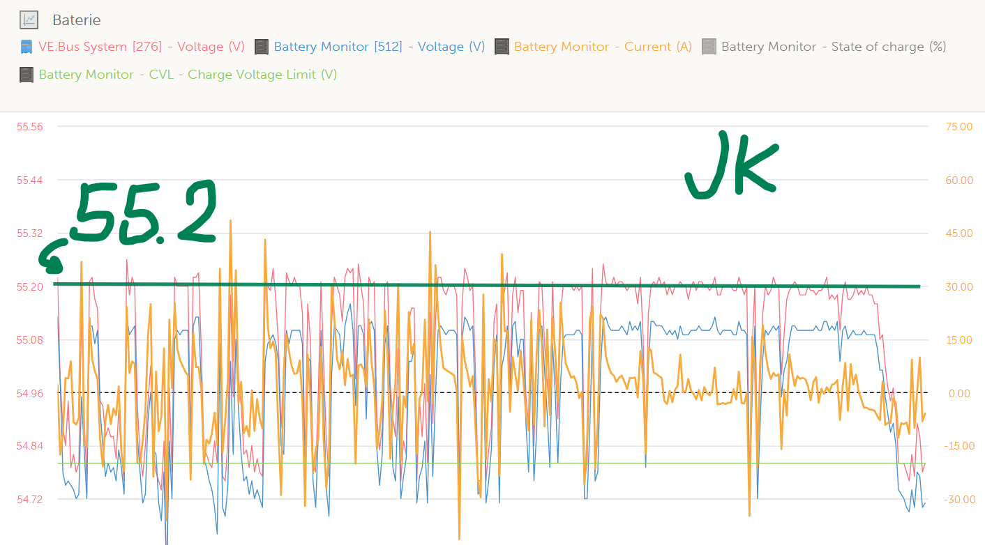
I maybe found a possible cause and it is VE.Bus System - Charge voltage setpoint.
It is probably send by BMS, bacause on other systems it is different or even changing almost every minute (JBD).
On JK Charging voltage setpoint is set at 0.4V higher than CVL. It changes with float from BMS and is again 0.4V higher.
Victron then limits charging voltage not to the CVL from battery but to “Charging voltage setpoint”.
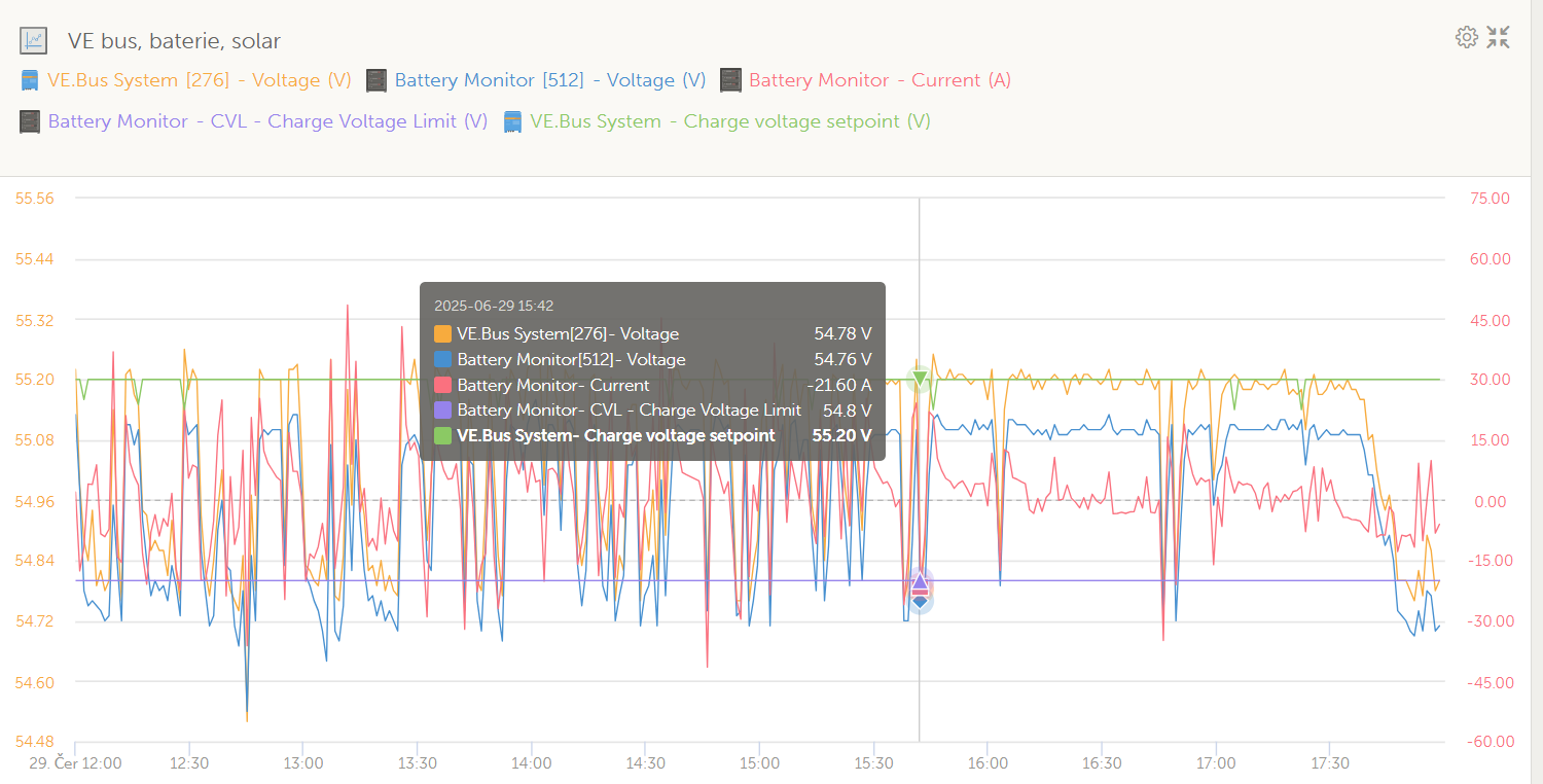
JK:
Battery CVL (float test): 54.8V
VE.Bus System - Charge voltage setpoint: 55.20V
CVL < Charge v. setpoint
Difference MINUS -0.4V
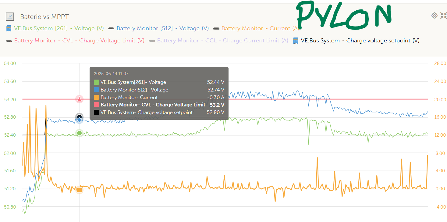
Battery CVL: 53.2V
VE.Bus System - Charge voltage setpoint: 52.80V
CVL > Charge v. setpoint
Difference PLUS 0.4V
Based on victrons guide. It should be set lower than CVL.
• Charge Stages:
Most Victron chargers go through different charge stages, including bulk, absorption, and float.
• Absorption Phase:
During absorption, the charger applies a constant voltage (the “charge voltage setpoint”) to the battery, allowing the battery to reach its full capacity.
• Float Phase:
Once the battery reaches the charge voltage setpoint, the charger switches to float mode, maintaining a lower voltage to keep the battery topped off without overcharging.
• Setting the Value:
The “charged voltage” setting in Victron devices is often used to calibrate the battery monitor as full, and it should be set slightly below the target absorption voltage (e.g., 0.2V less).
• Importance:
Proper configuration of the charge voltage setpoint is essential for battery health and longevity.
• Examples:
• For a 12V battery, the recommended absorption voltage might be 14.4V, and the charged voltage setpoint in a battery monitor would be 14.2V.
• For a 24V battery, the corresponding values would be 28.8V and 28.4V
Also discussed by me with more data in this thread from 27.6.2025 - Ignores discharge power to float voltage - #82 by k3ivi
I have send this issue to JK RnD engineers. Hope it can and will be fixed.
The inverter adds a 0.4V offset when exporting, for normal self-consumption modes it is not added.
Based for what I see it has nothing to do with Charge voltage setpoint, maybe it is adding it to the actual setpoint which is same as CVL? Is this 0.4V addition described somewhere?
JBD is changing a bit all day. If JKs CVL is 54.8V and charge voltage setpoint is 55.2V, battery is constantly being charged and discharged in the region based on MPPTs power and export. So between 54.8 and 55.2 charger can operate as he wants, resulting in what we see.
Pylon has it other way around as I wrote earlier. CVL from battery is higher then Charge voltage setpoint. So charger does not want to go above CVL 52.8V and does not move with voltage lower or higher all the time.
It is also interesting why battery voltage is higher than system bus voltage but it looks like bad battery BMS voltage calibration.
EDIT:
Victron really adds 0.4V to Charge voltage setpoint when selling to grid is enabled:
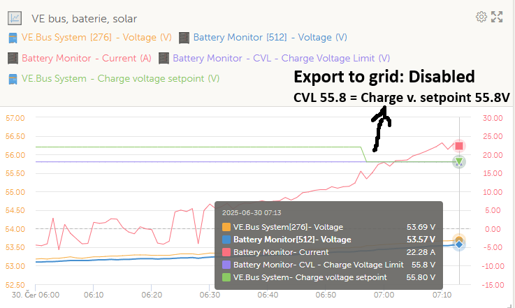

Now there is a million dollar question. How to handle this. I think Victron should disabled this addition somewhere. Otherwise BMS like JK, that does not send maximum charging voltage and does not rely on overcharging of cells to 3,65V to set battery to 100% resulting in disabled mosfets is impossible to set. And these types of BMSes with better charging behaviour will be more and more.
JK cannot send to Victron “Charge voltage setpoint” atleast 0.4V lower all the time to compensate for Victrons bad behaviour in case selling to grid.
Or can BMS overwrite this Victrons +0.4V addition?
And when you check other type of BMS - JBD. Even that does not help and battery is fluctuating between 55.2V and 55.6V (charge voltage setpoint) and causing same bad behaviour.
So does battery really needs to disable mosfets when charged to be able to work with Victron???

JBD BMS with disabled solar sell, again dropped charge voltage setpoint by 0.4V

Workaround: I simulated old fashioned “charge to the limit” BMSes.
BMS settings: RCV set to 3.599V per cell (totall charging voltage 57.5V plus 0.4V from Victron = 57.9V) , OVP to 3.6V to be sure I do not overcharge the cells but still hit OVP alarm and force battery to disable charging mosfets…
And guess what… it works… 0 current flow. Battery is kept charged at 100% while still easily exporting to the grid.


What is a “problem” that BMS is not designed to work this way and sends OVP alarm to Victron. If user is informed that it is normal it is acceptable. Second issue is it does not limit charging current with these high voltages and rely on natural LFP absorption. I think I can work around that with little lower voltage.
Maybe I will count with the 0.4V addition and set charging voltage and OVP little lower.
I have one brand new Multi RS Solar, with a BMS NG and two NG batteries. Attached to it is a single string of PV panels. It couldn’t be simpler.
Yet it continously switches from charging to discharging and v.v.
I believe what @darock says about the control algorithm is the key. I have two other problems (other threads) that are related to not properly detecting the state of the battery due to DC ripple:
-
it fails to sync SoC to 100% because it’s 3-minutes timer gets reset every time a small dip in voltage occurs
-
it fails to end absorption because of the same reason (timer 2h never reached)
-
it thinks the battery is not fully charged so it restarts the whole process of charging it.
These are my hypothesis. The only thing I cannot explain is why it also discharges repeatedly. I can only imagine that many things go wrong and a simple linear explanation is not possible.
Victron seems to be working on the first two issues. I wouldn’t be surprised if it touches the alternating (dis)charging problem as well.
Probably this is caused due to peak shaving. When the soc is low causing peak shaving to stop the system doesn’t switch between charging and inverting continously.
Most likely there will be an option to disable peak shaving completely in 3.70 which solves this issue.