I have my CL 12/100 connect to CCP2 (175A) in my Ford Transit with Dual 250A alternators, i've pulled 160a off it many times before. The van is putting out 14.2v - 14.3v consistently.
I'm using the renewable settings on my multiplus, with it set to stop charging at 13.3v, to give my solar panels and alternator space so i don't waste "free" power. My 10kw bank it usually has 2kw of space for solar/driving.
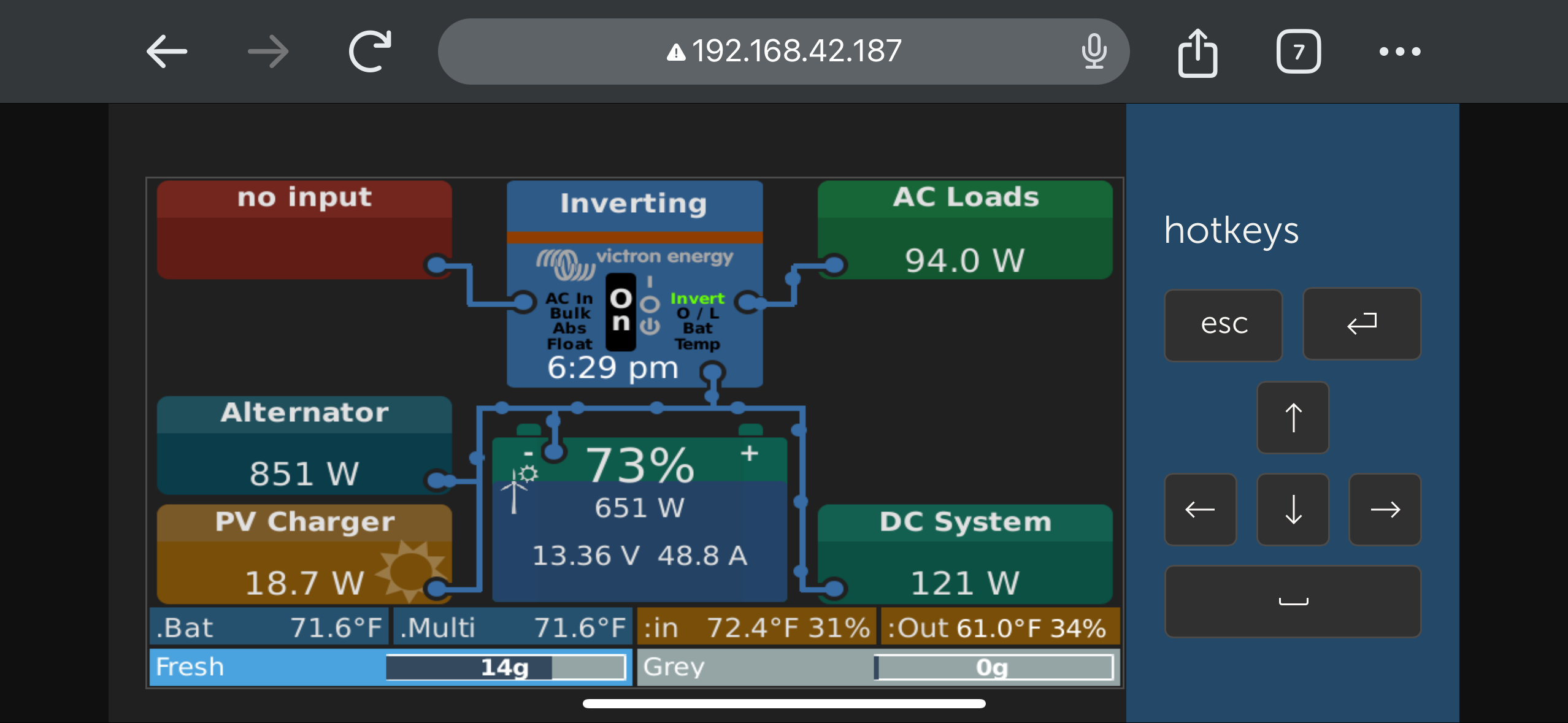
The problem is i can get down to 65% and be at 13.3v if i don't have any heavy loads. But it seems my CL12 starts to throttle when it sees above 13.3v, it drops the output current % and i'm only getting ~800w, or if it see 13.5v it drops to ~600w. If my solar panels are putting out 300w or more it throttles even more.
If i put a heavy load on the batteries that drops the voltage, it will jump back to 100% which is ~90A/1.2kw. Never seen higher than that.
Is there any way i can disable the throttling on the CL12?
asked
CL 12/100 Throttling at 65% SoC on 10kw bank
Went for a drive, it cloudy today and this is what im seeing.
@BadWolf Is there any way i can disable the throttling on the CL12?
Battery current limiting is the function of the battery output fuse . A 125a fuse gives the max current output of 100a.
The input voltage (13.9v) to the BMS is a bit lower than the alternator (14.2). The higher the input voltage to the BMS, the higher the charge current will be.
Check your alternator to BMS cable, and the battery to ground cables are rated to reduce the voltage drop.
I have it set for 100a output, with a victron 125a 58v fuse. I had the 32v version and just recently swapped to the 58v. I did see a charge current % improvement of about 10% with the 58v.
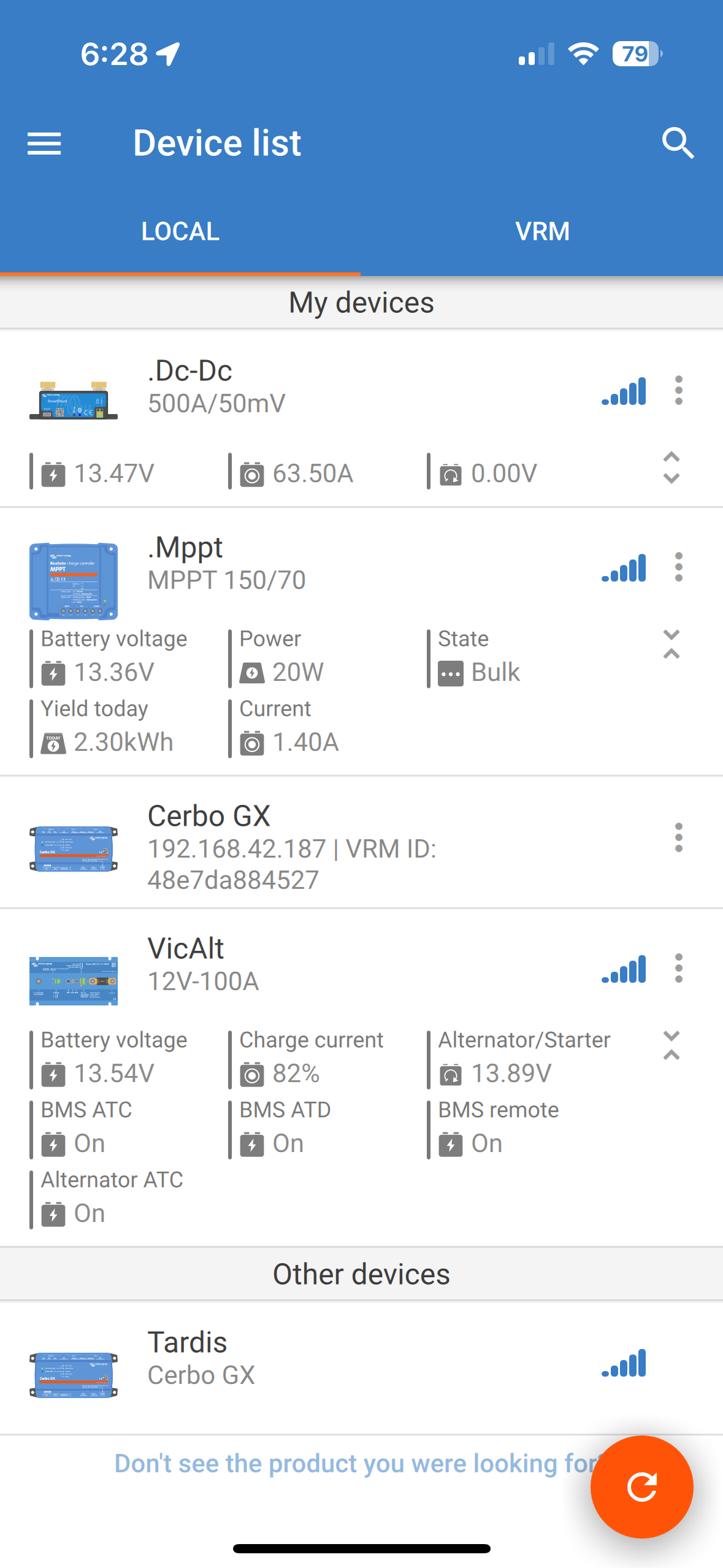
What i'm trying to prevent is the Charge Current % from dropping, it was at 82% in the photo above.
When i used the 100A fuse(that came with it) with the default 90A output max was 75A @ 100% current
When i use a 125A 58v fuse with the 100A output max is ~90A @100% current (was 85A with the 32v)
Using my Klein Volt Meter
When i turn on the CL12 the voltage output on ccp2 drops ~0.1v,(expected) and i'm seeing it at the end of the cable run (4ft 1/0 cu) on the terminal of the CL12. But the CL12 is reports 0.2v lower than that reading.
The fused side that is charging the house batteries shows 0.15v higher than the batteries when charging as well.
If i move the CL12 Ground to the starter battery it does eliminate the 0.2v drop to on the Starter reading but then adds it to the Battery Voltage.
@BadWolf If i move the CL12 Ground to the starter battery it does eliminate the 0.2v drop to on the Starter reading but then adds it to the Battery Voltage.
Given that information you have a 0.2v drop on your negative wiring. Also note that the Gnd for the CL12 has to originate via the Neg post of the battery being charged by the BMS to be accurate.
Further to that, any voltage measurements need to be taken from the BMS Gnd terminal. You can even measure the voltage difference between the BMS Gnd terminal and vehicle ground.
Attached is how its wired. The CL12 ground is attached to my house battery. Connecting it to the starter battery was a test to see if the voltages would change. I have a smart shunt on the ground off the Bus Bar in DC-DC/Alternator meter mode(calibrated to be with 0.4a of my klein clamp meter).
When the CL12 is on but not charging it sees the correct voltages on both side. When it runs it drops ~0.2v more on the starter side than the lug/terminal end measurement with a volt meter.
Ground from house to starter battery has no voltage difference, and my klein shows 0.00ohm resistance between them.
I'm wondering if i have a defective unit since when it runs 100% its always been ~12amp lower than it should be. 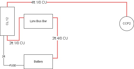
@BadWolf Ground from house to starter battery has no voltage difference, and my klein shows 0.00ohm resistance between them.
No. Cable always has some resistance, and given the currents involved some voltage drop occurs. Use a Voltage drop calculator as taking resistance measurements is pointless. Or you could measure the voltage drop from terminal to terminal for each cable section, and then add the results up.
Using the above calculator gives a voltage drop of 0.15686v for 16ft of 0AWG cable. Add in the extra resistance from 10 crimp / terminal connections, and 2 fuses and you will see the 0.3v of drop is seen in your OP.
Any resistance reduces current flow.
I'm not saying i don't have resistance, my meter doesn't do down to mOhms, i don't have enough to see on my meter. If i could see mOhms I'm sure it would show some resistance.
What I'm saying is measuring voltage on bolt/terminal coming out of the CL12 on the "starter" side to the same grounding point on the house battery, the CL12 is showing 0.2v-0.3v less than the volt meter, in the app.
@BadWolf What I'm saying is measuring voltage on bolt/terminal coming out of the CL12 on the "starter" side to the same grounding point on the house battery, the CL12 is showing 0.2v-0.3v less than the volt meter, in the app.
Your ground voltage reference point should be the Gnd terminal of the BMS. Next best the negative terminal of the battery.
What voltages do the batteries report?