question

ssybert avatar image
ssybert asked

Need help wiring contactor to REC Q BMS w/o pre-charge relay - emitter / collector pins?

Hi all, I asked this question in anther thread as part of a larger issue but think it may be best to be a separate topic as I cannot be the only person with this question.

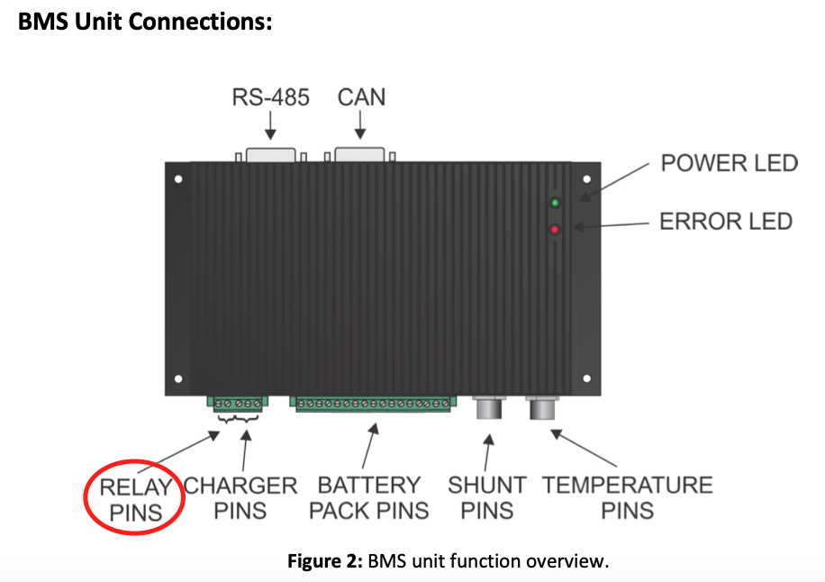
I have a REC Q BMS which I opted not to buy the pre-charge relay for. There is no documentation on how to wire the contactor to the BMS w/o the pre-charge circuit.

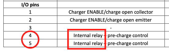
The pins on the BMS which the pre-charge relay would connect to are labelled "emitter" and "collector". I know these are legs of a transistor and doing some research, it sounds like the current flows through the collector, gets amplified and sent out the emitter. In this application, do I just feed the collector with +24v from my battery pack and drive the contactor from the emitter output? Will this just act as an open/closed circuit when the BMS wants to open/close the contactor?

Do I need an additional relay in between the contactor and BMS and NOT drive the contactor directly from the output of the emitter?

I wish there was better documentation on this. I'm leaving for a trip on Thursday and this is one of the last pieces of my puzzle. Any help from anyone familiar with the REC BMS products would be appreciated.

Scott


MultiPlus Quattro Inverter ChargerBMS
2 |3000

Up to 8 attachments (including images) can be used with a maximum of 190.8 MiB each and 286.6 MiB total.

2 Answers
markus avatar image
markus answered ·

Hi,

See screenshots below.

(Sorry for the edit but it might be misleading as it was before)

Pin 5 goes to V+, Pin 4 drives the contractor, this is how I have done it and it works.

Best Regards,

Markus

1 comment
2 |3000

Up to 8 attachments (including images) can be used with a maximum of 190.8 MiB each and 286.6 MiB total.

markus avatar image markus ♦♦ commented ·

Be sure that you use the right pins:

1629226944440.png


0 Likes 0 ·
1629226944440.png (137.6 KiB)
1629227128921.png (27.3 KiB)
baxter avatar image
baxter answered ·

Sorry to hijack this thread.


I am also using REC BMS within a 3ph ESS (3 Multiplus II and one RS450). Is the pre-charge unit needed in that setting? The contactor should always be energized, it is just the line of last defence if something goes wrong with the battery.

2 comments
2 |3000

Up to 8 attachments (including images) can be used with a maximum of 190.8 MiB each and 286.6 MiB total.

markus avatar image markus ♦♦ commented ·
Hi baxter,

strongly depending on size of your Multis, the inrush current could be harmful for a contactor and it will most probably die, if it has to switch on an un-energized system too often or maybe even once. You should refer to the contactors datasheet for info on max. allowed inrush current.

That being said, if you are fully aware of that and use the contactor as a last defense opener and within its rated switching amps only, it will technically work.

If you have grid available, you could use the grid to pre-charge the system, or alternatively you could pre charge the (switched off) system with a resistor. If you use a light bulb as resistor (or 4 12V bulbs in series), you can see the pre-charge process by the glow of the bulbs.

You should ask REC, how to set up the BMS to only switch the contactor on, to an energized system.

When there is no grid available, you could use the light bulb over the contactor terminals to energize the system, only if the BMS detects proper voltage on inverter side, it should switch the contactor on.

BR

0 Likes 0 ·
baxter avatar image baxter markus ♦♦ commented ·
Thanks a lot for your answer and very helpful input!
0 Likes 0 ·