question

niccolaiddis avatar image
niccolaiddis asked

Grounding Off-Grid System - Some questions

Hello everybody,

in the past few months I've been designing the off-grid system for my farm, with the help of an electrician. I already bought (almost) all the components and I'm installing it right now.


Now, I find myself stuck with the grounding of the system, because I'm not quite sure how I should wire the whole system so that it's as safe as it should be.

As a side note, consider the following:

  • I know that it is advised to ask this kind of questions to a qualified electrician who knows the local regulations, but believe me, where I live (rural Panama) it's actually pretty hard to find one, let alone someone with experience with Victron products. In fact, I had to buy 80% of my components from the US because nobody sells them here. (for example it was literally impossible to find flexible wires, I had to buy them on Amazon. Same for 4/0 copper wire lugs and the tool to install them)
  • regarding local regulations, forget about it, there are no specific regulations and nobody checks whether what I'm doing is good or not. The person in charge in this town does not know anything about off-grid systems, and is in fact waiting for me to complete my system so that he can see how it works


I had some help from en electrician online, and of course I studied all what I could find online, but there are some things that I'm not sure about, so maybe you can help me out.

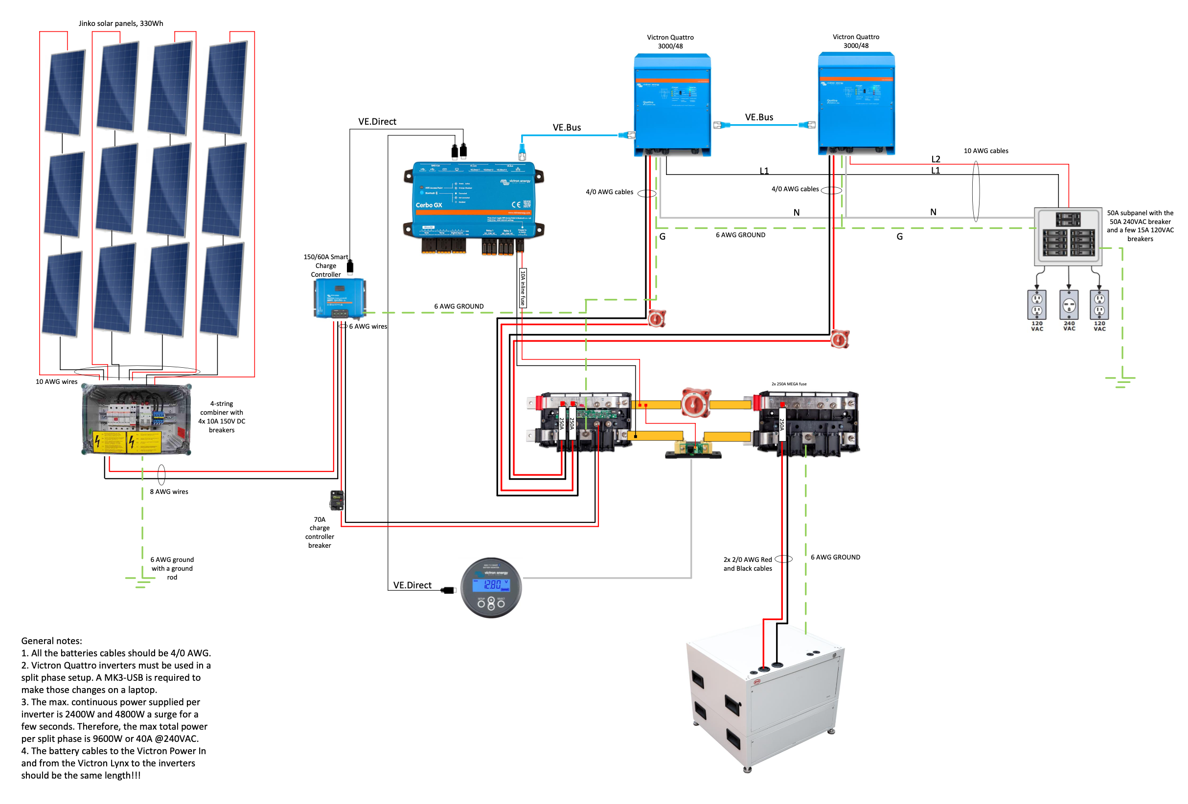
Please find attached the diagram of the system (It's a work in progress).

Electrical Drawing with 1x BYD LVL.pdf

I believe that the grounding wiring needs to be fixed, because:

  • 6 AWG for grounding the inverter is too small of a wire, because from reading Wiring Unlimited I think the wire should be tick enough to be able the carry the full current, which in my case is 250 amps, so the wire should be 4/0 AWG
  • it's not clear what happens between chassis grounding and AC grounding. Is it a floating system? Do I need one RDC before the AC distribution? Does the PV part of the system have a dedicated ground rod for lightning protection?


This is where I'm stuck.

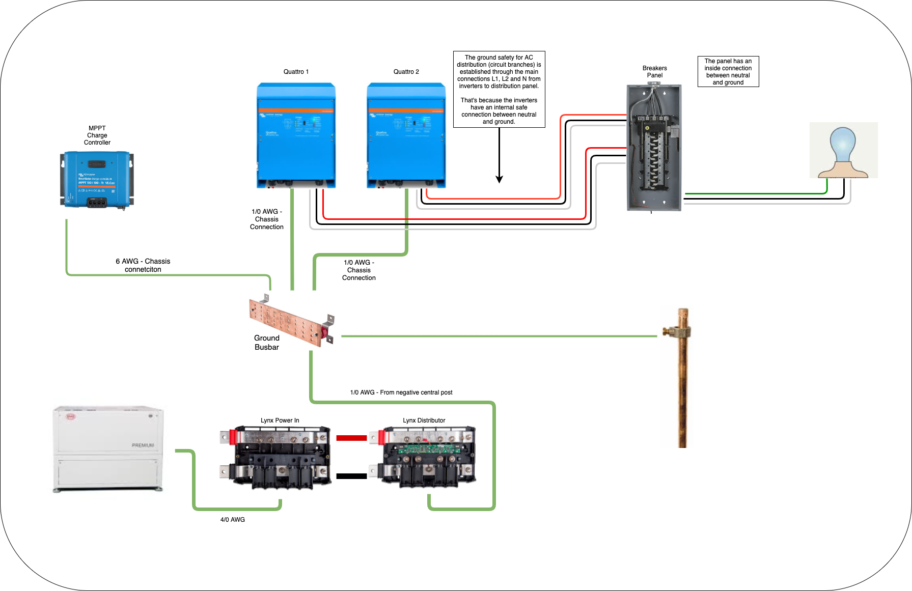
From my understanding, I think the grounding should be fixed as follows:

  • the metal frames of the PV panels should be grounded with a ground rod
  • the ground output of the PV combiner box should be connected to the same ground rod
  • all the chassis of the components (the two inverters and the charge controller) should be connected in parallel with tick wire, and then connected to the central ground terminal of the Lynx Distributor
  • from there, I should run a 4/0 AWG wire to a ground busbar (not shown in the diagram), where I should also connect the grounding wire for the AC distribution panel
  • this ground busbar is connected to another dedicated ground rod
  • there should be a RDC breaker between the inverters and the AC distribution panel.


Well, there's that, not sure what I'm missing, but I'm sure that something is missing in my understanding of the whole grounding deal.


I appreciate any help!


Edit: I added a screenshot of the diagram.


schermata-2021-08-11-alle-45528-pm.png


MultiPlus Quattro Inverter ChargeroffgridGrounding
2 |3000

Up to 8 attachments (including images) can be used with a maximum of 190.8 MiB each and 286.6 MiB total.

5 Answers
Kevin Windrem avatar image
Kevin Windrem answered ·

There are two purposes for the safety ground (aka PE) connection.

First is a path for fault currents. If load develops a short between the hot leg and the chassis, the chassis will be elevated to the voltage of the hot leg unless there is a path from the chassis to the neutral leg at the source. This is different from the neutral conductor run to all loads and normally carries the return current. In normal electrical systems, there is a connection between the safety grounds from the branch circuits to the neutral conductor where the service enters the building. So if there is a fault in a piece of equipment, the current flows back to the service entrance safely and trips the branch circuit breaker or fuse.

There can also be fault paths for the DC side of a system like you are building. A floating chassis could reach the battery voltage and is less lethal but there could still be opportunities for system damage due to the high currents involved. So the same safety ground mechanism should be in place.

The safety ground circuitry doesn't need to be as large as the normal current carrying conductors. It's there only to trip the breaker or blow the fuse and to keep equipment cabinets at a safe voltage relative to "earth". Typically, 1/4 the cross-sectional area is sufficient but check local codes.


The "earth" connection is a continuation of the safety ground to the earth by way of a ground rod. This is a relatively high resistance path and is not a substitute to the safety ground connection to neutral at the service entrance. In fact, a ground rod may not even trip a 20 amp breaker. The purpose of this earth connection is to drain any static charge off the electrical system. Without an earth connection to the safety ground system, a nasty static charge could build up on the chassis of the vehicle or metal parts of a building. Earth connections carry very little current and can be on the small side.


Most Victron inverters and inverter/chargers include two important relays: an AC input relay that disconnects the grid from the inverter/charger core and the AC output; a ground relay that makes a neutral/safety ground connection. The ground relay is open when the AC input relay is closed because the incoming AC already has a neutral/safety ground connection up stream (at the service entrance). But when the inverter disconnects from the AC input there is no neutral/safety ground connection, so the ground relay closes. The ground relay then allows fault current to return to the neutral side of the inverter.

Some generators "bond" its neutral to the generator chassis internally. Some (most?) to not. The reason a generator does not have a neutral/safety ground connection is to avoid issues when the generator is connected to a transfer switch feeding a panel. Transfer switches typically do not switch the neutral connection. So the service entrance provides the neutral/safety ground path (there can only be ONE such connection).

When generators are used in an off grid situation, it's essential the installer creates an appropriate neutral/safety ground connection for the generator.

I'm not sure why but portable generators often do not have an internal neutral/safety ground connection. So its AC output floats relative to it chassis and the chassis of anything plugged into it. If a fault occurs, there is not return current path and the equipment chassis will be connected to the hot side of the AC from the generator. But this is a little less dangerous since the neutral will simply float allowing the hot leg to rest at the chassis ground voltage. That is unless another device has a neutral/safety ground fault!

3 comments
2 |3000

Up to 8 attachments (including images) can be used with a maximum of 190.8 MiB each and 286.6 MiB total.

shaneyake avatar image shaneyake commented ·
@Kevin Windrem Can you explain why you would or would not join the DC - to ground? Like pictured above.


In all my installs I never connect the DC - to ground, other than though some surge protection to avoid any static build up in the DC system.

A lot of the system I work on require isolation fault detection equipment, so DC- to ground would trip the system off but this is expensive for small installs.

0 Likes 0 ·
Fideri avatar image Fideri commented ·

@Kevin Windrem

I understand your thoughts. Given that you understand the subject and Victron equipment quite well, what should I do in the case of many Quattros in parallel in an off-grid context to avoid creating multiple ground/neutral bonds in the system? Disable the ground setting on all but one Quattro? Or this is automatic when operating multiple Quattros in parallel?

Fideri

0 Likes 0 ·
Kevin Windrem avatar image Kevin Windrem Fideri commented ·
Sorry, I do not know the official Victron position on the subject. Hopefully someone from Victron will reply.
0 Likes 0 ·
niccolaiddis avatar image
niccolaiddis answered ·

@Kevin Windrem Thank you for your detailed reply.


I'll try and dissect your reply to see if I can turn it into practical wisdom applicable to my system, like a 5 year old would do.

If I do something wrong it's an opportunity to fix it and allow other people not to make the same conceptual/practical mistakes.


First is a path for fault currents. If load develops a short between the hot leg and the chassis, the chassis will be elevated to the voltage of the hot leg unless there is a path from the chassis to the neutral leg at the source. This is different from the neutral conductor run to all loads and normally carries the return current.


So if something catastrophically wrong happens inside one of the components, let's say inside the Quattro inverter/charger, the positive wire can touch the chassis. At this point, the new path of current could be through the chassis, if someone like me ignores this stuff and touch the chassis together with (let's say) the negative busbar. Now the circuit is close, I'm part of the new path and I'm fried.

For this reason, a ground connection is needed, which is a cable connected to the chassis of the components, back to the negative busbar (which is source, being connected to the battery bank). In my case that would be the central negative connection inside the Lynx Distributor.

When such connection is established, and something goes wrong inside one of the components, the new path of the current will be through this new ground wiring, because it offers way less resistance than my body.


So...lesson number 1: all chassis of all the components should be wired together and connected to the negative busbar.

Am I right?


In normal electrical systems, there is a connection between the safety grounds from the branch circuits to the neutral conductor where the service enters the building. So if there is a fault in a piece of equipment, the current flows back to the service entrance safely and trips the branch circuit breaker or fuse.


This would be the AC side of the system, where a safe neutral/ground connection is established inside the AC distribution (the panel with breakers)?

If something goes wrong in one of the branches (i.e. hot wires touches the metal casing of a lamp), the current has a way back to the source (which is the breaker) through the green ground connection that is (hopefully) provided with the lamp ---> the breaker opens the circuit (and shuts down the current).


Lesson number 2: all branch circuits in AC side, should have a ground from equipment/appliance back to the breakers panel. Also, make sure that the breaker panel has neutral/ground connected together (ground busbar connected to neutral busbar, inside the panel).


There can also be fault paths for the DC side of a system like you are building. A floating chassis could reach the battery voltage and is less lethal but there could still be opportunities for system damage due to the high currents involved. So the same safety ground mechanism should be in place.


I guess "floating chassis" == no ground connection between chassis and negative busbar?

This is already covered in lesson number 1, right?


The safety ground circuitry doesn't need to be as large as the normal current carrying conductors. It's there only to trip the breaker or blow the fuse and to keep equipment cabinets at a safe voltage relative to "earth". Typically, 1/4 the cross-sectional area is sufficient but check local codes.


In DC side, that would be 1/0 AWG, because I'm using 4/0 AWG from +/- busbar to inverters.

So it's not 4/0 AWG as I said, but neither is 6 AWG. Correct?


The "earth" connection is a continuation of the safety ground to the earth by way of a ground rod. This is a relatively high resistance path and is not a substitute to the safety ground connection to neutral at the service entrance. In fact, a ground rod may not even trip a 20 amp breaker. The purpose of this earth connection is to drain any static charge off the electrical system. Without an earth connection to the safety ground system, a nasty static charge could build up on the chassis of the vehicle or metal parts of a building. Earth connections carry very little current and can be on the small side.


So the ground rod is needed to drain the static charge, and being no substitute for a safety ground connection between all the chassis' components (DC side) and all circuit branches (AC side), it should be implemented together with said safety ground connection.


Lesson number 3: a ground rod is a needed addition to the safety of the system. I should connect the whole ground wiring (DC and AC) to a ground rod.


Probably my best bet would be to wire the DC ground (from Lynx Distributor) and the AC ground (from breakers panel) to a dedicated ground busbar, and then to a dedicated rod.


Most Victron inverters and inverter/chargers include two important relays: an AC input relay that disconnects the grid from the inverter/charger core and the AC output; a ground relay that makes a neutral/safety ground connection. The ground relay is open when the AC input relay is closed because the incoming AC already has a neutral/safety ground connection up stream (at the service entrance). But when the inverter disconnects from the AC input there is no neutral/safety ground connection, so the ground relay closes. The ground relay then allows fault current to return to the neutral side of the inverter.


I'm pretty sure that my Quattros do have such neutral/ground internal connection.

And because what I have is an off-grid system, with absolutely no AC inputs for the inverter (no grid, no generator, no nothing), the neutral/ground connection is automatically established by the inverter, inside the inverter.


(I believe there's a checkbox inside the inverter configuration, I just have to make sure that it's checked so that the connection is established).


Which means that if a ground fault occurs, a safe path for the current is automatically established (provided the ground wiring). And the 250 amp fuses are in charge of shutting down the current if something bad happens (same as the breakers for the AC side).


Lesson number 4: if an inverter/charger is powered by both a battery bank AND the grid (or a generator), this whole ground safety connection scenario is a lot more complicated, and is highly dependent of the specs of the components.

Such as:

  • does the inverter have a neutral/ground connection inside?
  • does the generator have a neutral/ground connection inside?
  • are you installing the right ground connections without creating ground loops?


But all of this would not change what happens for the ground connections for the AC output side of the system: the breakers panel and circuit branches (see lesson number 2 and 3).


I hope my attempt will be useful for other people.

Let me know if something went wrong in my analysis!

2 |3000

Up to 8 attachments (including images) can be used with a maximum of 190.8 MiB each and 286.6 MiB total.

niccolaiddis avatar image
niccolaiddis answered ·

UPDATE: some stuff shown below is wrong. I'll update the diagram when everything has been fixed!


Ok I made a potato quality digram to summarize the whole grounding of my system, apart from the PV array which I guess deserves its own grounding rod.

I have a couple of questions:

  • is it correct that I do not have to run a ground cable from the breakers panels to the main ground busbar, as I wrote in my previous reply? Reasoning being that the ground protection for the AC circuit branches is provided by inverters themselves, thanks to their internal neutral/ground connection. Which means that any ground fault in AC distribution will be redirected to the source, meaning the inverters, through the neutral wire.


  • what happened to the RDC/GFCI? Wiring Unlimited says that in my case, I should install it just before the loads, which in my case would be between inverters and breakers panel. So that would mean to install a RDC/GFCI in the L1/L2/N wiring. But I've got two inverters, so should I install two RDCs/GFCIs? That's not clear to me.


Consider that with this system I'm powering both 120V and 240V loads, but it was impossible to find any 240V Victron inverter where I live, so I decided to buy two 120v Quattros and use them in split-phase.


grounding.png (2.9 MiB)
7 comments
2 |3000

Up to 8 attachments (including images) can be used with a maximum of 190.8 MiB each and 286.6 MiB total.

Kevin Windrem avatar image Kevin Windrem commented ·

The breaker panel is NOT the correct place to create a safety ground to neutral bond!!!!! This bond is made in the service entrance (when there is one) and all components down stream of this must keep safety ground and neutral separate. Otherwise you inject neutral current in the safety ground circuits (ground loops).


In the case of an off-grid system with no AC source, the safety/neutral bond is made inside the inverter WHEN it is operating without an AC source. In the case of a generator, the inverter will open it's ground relay and expect the safety/neutral connection to be made upstream. So the generator should create this safety/neutral connection either internally or in the wiring between the generator and the inverter input.

Most of the discussion regarding safety is related to AC wiring. Most DC wiring can have the same issues but since the voltages are less, shock hazard goes way down. A 48 volt battery system could in fact cause a shock in moist environments though.

shaneyake makes an interesting point. I had never considered a completely floating DC system. In an RV for example that has a DC system of loads, the DC negative IS bonded to the chassis at some point. In cars, the chassis is often used AS the DC neutral which could potentially cause ground loop issues. My gut says it is a good idea to have a single-point connection between DC negative and safety ground.

The AC distribution panel does need a safety ground connection. I would use the safety ground bus bar as the common point for all safety ground connections. Some flexibility is possible as long as wire size is properly considered.

An RCD is always a good idea and may be required by local codes. An RCD between the inverters and the breaker box protects the entire system as long as it's trip current can be set low enough. Otherwise, branch circuit RCDs may be indicated (or required by code).


0 Likes 0 ·
shaneyake avatar image shaneyake Kevin Windrem commented ·

I personally would not connect the DC to ground.

If DC- is connected to ground then you could accidentally touch the case of the equipment and let's say a battery lug and you could get a shock or burn. If the DC- is floating then you would have to touch both Pos and Neg Battery lugs, this is a lot harder to do than Case and Pos terminal or lugs.

I would connect battery case to ground but not the DC negative. From my perspective it is safer to have DC system floating, as you would need 2 independent failures before you could shock someone. The grounding connection on the Lynx is mostly for Vehicle installs where the chassis is DC-

1 Like 1 ·
niccolaiddis avatar image niccolaiddis shaneyake commented ·
So your suggestions is to remove the ground wire from the Lynx Distributor to the main ground busbar, while still grounding the battery case to the ground busbar, without touching the Lynx Power In.


Am I right?

0 Likes 0 ·
shaneyake avatar image shaneyake niccolaiddis commented ·
Correct.
0 Likes 0 ·
shaneyake avatar image shaneyake shaneyake commented ·

@niccolaiddis I would actually recommend that you follow the Wiring Unlimited guide from Victron. Grounding is on Page 64 but the whole document would be good for you to read. They do connect DC- to GND.

https://www.victronenergy.com/upload/documents/Wiring-Unlimited-EN.pdf

0 Likes 0 ·
niccolaiddis avatar image niccolaiddis Kevin Windrem commented ·

Got it, I understand that the neutral/ground connection should be made in just one point in the system, and the Victron Quattros do have such connection.


So all the branches' grounds will be connected to the ground busbar inside the breaker box, and then I'll run another wire from that busbar to the main ground busbar, where also all the DC components are grounded.


I'll update the diagram so that nobody does what was shown!


Last question if I can ask...

Each Quattro has the following AC output terminals: Line, Neutral and Ground, as shown below (blue box):


schermata-2021-08-13-alle-102542-am.png

In the manual it says the following:

The Quattro is provided with a ground relay (see appendix) that automatically connects the N output to the casing if no external AC supply is available. If an external AC supply is provided, the ground relay will open before the input safety relay closes (relay H in appendix B). This ensures the correct operation of an earth leakage circuit breaker that is connected to the output.    
In a fixed installation, an uninterruptable grounding can be secured by means of the grounding wire of the AC input. Otherwise the casing must be grounded.                           


Does that mean that if I don't have any AC inputs, that ground terminal should not be used, and I directly use the chassis connection instead (green circle in the picture)?

0 Likes 0 ·
Kevin Windrem avatar image Kevin Windrem niccolaiddis commented ·
PE is connected to the chassis inside the Quatro.
0 Likes 0 ·
Kevin Windrem avatar image
Kevin Windrem answered ·

All of the Victron system diagrams that show ground wiring detail has the Multi/Quatro chassis connected to the battery negative busbar. This will connect the battery negative to the AC safety ground through the internal wiring inside the Multi/Quatro. Also an earth connection is shown to this negative busbar.

E.g.,:

https://www.victronenergy.com/upload/documents/MultiPlus-system-example-3KW-24V-120V-AC.pdf


3 comments
2 |3000

Up to 8 attachments (including images) can be used with a maximum of 190.8 MiB each and 286.6 MiB total.

shaneyake avatar image shaneyake commented ·
@Kevin Windrem Yes, but all of those diagrams are for Boats or RVs and in that case I agree with them that you should connect the DC- to the frame for the boat or RV/van. I don't disagree and in my RV I have bonded chassis and DC-.


For fixed applications, where a reliable ground is present, I don't see why you would do this and I actually think it creates a less safe system.

Main differences I see are that, because of the true earth, any charge that is built up on the cases or grounding system, will dissipate to the earth. This is referring to EMI and static charge.
The other main difference is that the environment is not conductive and if I wire has a cut in it or touches something it is very unlikely it will find a return path and even if it does, it will be such a low current that it won't blow the fuse or trip the BMS.

If you could please explain to me why you think this DC- GND connection is useful or what purpose it is meant to serve, I am happy to learn.

0 Likes 0 ·
Kevin Windrem avatar image Kevin Windrem shaneyake commented ·
With the DC system floating, a double fault could create a fire. Suppose there is a connection somewhere in the system between the battery negative and chassis and that the wire is small. Then a sort in the positive battery lead to ground will run current through the small wire but because it's resistance is high relative to the fuse, the current continues.


With a grounded negative (assuming the connection is large enough to carry the DC fault current), the fuse/breaker will open just like in the AC system.

Yes it takes two faults, or an unintentional negative to ground connection through some device.

0 Likes 0 ·
shaneyake avatar image shaneyake Kevin Windrem commented ·

Yeah, I guess it is a trade of between what you think is likely to happen.


As with Grounded Negative system you still have the possibility of a high resistance fault and fire, you are just hoping it hits the case blows and the fuse. I wonder if you actually have a higher chance of that happening due the fact that houses are fairly non conductive if the fault occurs outside of an enclosure. Like if moist plywood comes in contact with a cut in a positive cable then current would flow through the wood and into the screws holding the Quattro as they are at DC- Negative potential. This would then heat up the wood and set it on fire.


For a lot of the systems I work on we have isolation fault detection equipment. This triggers the BMS to shut the system down if there is a fault.
https://www.benderinc.com/products/ground-fault-monitoring-ungrounded/isometer_isopv425-with-agh420
Or ABB
https://new.abb.com/products/1SVR730660R0100/cm-iws-1s
This is extra cost that I don't think smaller systems need.

In my mind 2 faults are unlikely and you can test for a single fault easily with a multimeter. Could be part of the annual inspection.

0 Likes 0 ·
johnsmith avatar image
johnsmith answered ·

For Land based PV installs:-

A connection to earth of any of the current carrying d.c. conductors is not recommended. However,
earthing of one of the live conductors of the d.c. side is permitted, if there is at least simple
separation between the a.c. and the d.c. side. Where a functional earth is required, it is preferable
that where possible this be done through high impedance (rather than directly).

Connecting to earth is a very complex duscussion and many have opposing opinions. I have pasted the guidelines from our "PV Land" installs here in the UK. Please feel free to digest and comment.

Guide to the Installation of Photovoltaic Systems
38
2.2 Design Part 2 – Earthing, Protective Equipotential Bonding and Lightning
Protection
2.2.1 Lightning Protection
Whilst this installation guide does not cover specific guidance on selection, or application of
lightning protection, it was felt that a brief overview was required as given below. Where further
information is required, this can be referenced from BS EN 62305.
In most cases the ceraunic value (number of thunderstorm days per year for a given installation
location in the UK) does not reach a level at which particular protective measures need to be
applied. However where buildings or structures are considered to be at greater risk, for example
very tall, or in an exposed location, the designer of the a.c. electrical system may have chosen to
design or apply protective measures such as installation of conductive air rods or tapes.
If the building or dwelling is fitted with a lightning protection system (LPS), a suitably qualified
person should be consulted as to whether, in this particular case, the array frame should be
connected to the LPS, and if so what size conductor should be used.
Where an LPS is fitted, PV system components should be mounted away from lightning rods and
associated conductors (see BS EN 62305). For example, an inverter should not be mounted on an
inside wall that has a lightning protection system down conductor running just the other side of the
brickwork on the outside of the building.
Where there is a perceived increase in risk of direct lightning strike as a consequence of the
installation of the PV system, specialists in lightning protection should be consulted with a view to
installing a separate lightning protection system in accordance with BS EN 62305.
Note: It is generally accepted that the installation of a typical roof-mounted PV system presents
a very small increased risk of a direct lightning strike. However, this may not necessarily be the
case where the PV system is particularly large, where the PV system is installed on the top of a tall
building, where the PV system becomes the tallest structure in the vicinity, or where the PV system is
installed in an open area such as a field.
2.2.2 Earthing
Earthing is a means of connecting the exposed conductive parts to the main earthing terminal,
typically this definition means the connection of metallic casings of fixtures and fittings to the main
earthing terminal via a circuit protective conductor (cpc).
Importantly, it must be noted that we only make this connection when the accessory or appliance
requires it. This connection is required when it is considered to be a class I appliance or accessory
and is reliant on a connection with earth for safety using ‘automatic disconnection of supply’ (ADS)
as the fault protective measure.
Guide to the Installation of Photovoltaic Systems
39
As the d.c. side of PV systems is a current limiting generating set, the protective measure ADS is
almost never used and is outside of the scope of this guidance. In these circumstances, where the
d.c. side of the installation is constructed to meet the requirements of an installation using double or
reinforced insulation, no connection to earth between the PV Modules or frame and main earthing
terminal would be required.
Earthing of the inverter at the a.c. terminations will still be necessary where the inverter is a
Class I piece of equipment and must be applied where necessary. Where class I inverters are used
externally (ie field mount systems) careful consideration must be given to the requirements for
earthing.
2.2.3 Protective Equipotential Bonding
Protective equipotential bonding is a measure applied to parts of the electrical installation which,
under fault conditions may otherwise have a different potential to earth. By applying this measure
the risk of electric shock is limited as there should be little or no difference in voltages (potential
difference) between the parts that may otherwise become live. These parts are categorised as either
Exposed-Conductive-Parts or Extraneous-Conductive-Parts
In most PV systems there are no parts that are considered to be an exposed-conductive-part or
extraneous-conductive-part, therefore protective equipotential bonding is not usually required. For
guidance on when to consider protective equipotential bonding please see the decision tree on the
next page.
On the d.c. side of the PV installation the designer will have usually already selected double
or reinforced insulation as the protective measure and therefore the component parts of the
installation will be isolated and will not require protective equipotential bonding.
Guide to the Installation of Photovoltaic Systems
40
Earthing and or Bonding Decision Tree:
5 1
Earthing and/ or bonding of PV array frames
Is the d.c. side of the installation constructed to meet the requirements for an
installation using double or reinforced insulation as a protective measure?
Is the PV array frame an extraneous
conductive part
Is the array frame an exposed
conductive part ?
No protective
equipotential
bonding required
Protective equipotential
bonding as defined in
BS7671 should be applied
Earthing should be
applied if required
by BS7671
YES
YES YES
NO
NO
NO
Fig 10
Guide to the Installation of Photovoltaic Systems
41
2.2.4 Determining an Extraneous-Conductive-Part
The frame of the array has to be assessed as to whether it is likely to introduce a potential into the
installation. This aim of this assessment is to find out if the frame has any direct contact with ground
that would make it introduce a potential.
The details on carrying out these tests are best given in the IET BS 7671 Guidance Note 8 Earthing
& Bonding and this should be referred to before undertaking a test. The principle behind the test is
to ascertain whether or not there is a low enough conductivity between the part under test and the
Main earthing terminal (MET) to say that it could introduce an earth potential.
To find this out a resistance test should be carried out between the part in question (the array
frame) and the MET of the building. Where the value recorded is greater than 22kΩ (most cases)
the part can be considered to be isolated from earth and NOT an extraneous conductive part. If
however the reading is less than 22kΩ, then the part is considered to be extraneous and protective
equipotential bonding, as required by BS 7671, should be applied.
Where the array frame is mounted on a domestic roof or similar, the likelihood of the frame being
an extraneous-conductive-part is very low - due to the type and amount of material used between
the ground and the roof structure (which will mainly be non-conductive). Even in the case of an
array frame being mounted on a commercial building where mostly steelwork is used, it is likely that
the frame will be either isolated, and therefore not required to be bonded, or will be bolted to the
framework or steelwork of the building which will often be sufficient to maintain bonding continuity
and a sufficiently low enough resistance to consider it to be bonded through the structure itself.
Careful consideration needs to be given to systems that are ground mounted as they may initially
appear to be an extraneous-conductive-part. However, as they are usually a good distance away
from the earthed equipotential zone, by bonding them you may well be introducing a shock risk that
wasn’t there initially, and in the case of an installation supplied by a TN-C-S (PME) supply you may
be contravening the supply authority’s regulations (ESCQR 2002). In most cases these installations
wouldn’t require bonding – in such cases the designer must make an informed decision based on the
electrical design of the entire installation, not just the PV system in isolation.
2.2.5 System Earthing (d.c. Conductor Earthing)
There are a variety of possible PV array system d.c. earthing scenarios which can be broadly
summarised as follows:
No earth connection•
Hardwired connection of positive or negative conductor to earth•
Centre tapped array – with / without earth connection•
High impedance connection of positive or negative conductor to earth (for functional reasons)•
Guide to the Installation of Photovoltaic Systems
42
The manufacturer’s instructions for both the PV modules and the equipment to which the PV array is
connected must be taken into account in determining the most appropriate earthing arrangement.
A connection to earth of any of the current carrying d.c. conductors is not recommended. However,
earthing of one of the live conductors of the d.c. side is permitted, if there is at least simple
separation between the a.c. and the d.c. side. Where a functional earth is required, it is preferable
that where possible this be done through high impedance (rather than directly).
The designer must confirm whether the inverter is suitable for earthing of a d.c. conductor.
Transformerless inverters will not be suitable, and an earthed conductor may interfere with the
inverter’s built-in d.c. insulation monitoring. Hence, if an earthed d.c. conductor is required, this is
ideally done in the inverter in accordance with guidance from the inverter manufacturer.
NOTE: In the case of PV systems connected to an inverter, IEC62109-2 (Safety of Power convertors
for use in photovoltaic power systems – Part 2: Particular requirements for inverters), includes
requirements according to the type of earthing arrangement (and inverter topology). These
include minimum inverter isolation requirements, array ground insulation resistance measurement
requirements and array residual current detection and earth fault alarm requirements.
2.2.5.1 Systems with High Impedance Connection to Earth
A high impedance connection to earth of one of the current carrying conductors may be specified
where the earth connection is required for functional reasons. The high impedance connection
fulfils the functional requirements while limiting fault currents.
Where a functional earth is required, it is preferred practice that systems be functionally earthed
through high impedance rather than a direct low impedance connection (where possible).
2.2.5.2 Systems with Direct Connection to Earth
Where there is a hardwired connection to earth, there is the potential for significant fault currents
to flow if an earth fault occurs somewhere in the system. A ground fault (earth fault) interrupter
and alarm system can interrupt the fault current and signal that there has been a problem. The
interrupter (such as a fuse) is installed in series with the ground connection and selected according
to array size. It is important that the alarm is sufficient to initiate action, as any such earth fault
needs to be immediately investigated and action taken to correct the cause.
An earth fault interrupter shall be installed in series with the earth connection of the PV array
such that if an earth fault occurs the fault current is interrupted. When the earth fault interrupter
operates, an alarm shall be initiated. The nominal overcurrent rating of the interrupter shall be as
follows:
Guide to the Installation of Photovoltaic Systems
43
Array size Overcurrent rating
≤3kWp ≤1A
3- 100KWp ≤3A
>100kWp ≤5A
The earth fault alarm shall be of a form that ensures that the system operator or owner of the
system becomes immediately aware of the fault. For example, the alarm system may be a visible or
audible signal placed in an area where operational staff or system owners will be aware of the signal
or another form of fault communication like Email, SMS or similar
NOTE: In grid connected systems, an earth fault alarm may be a feature of the inverter. In such
systems and where the inverter is located in a remote location, the system should be configured
so that a secondary alarm is triggered that will be immediately seen by the system operator. For
systems in accordance with BS 7671 conductors used for earth fault detection are usually cream in
colour.
2.2.6 Surge Protection Measures
All d.c. cables should be installed to provide as short runs as possible and positive and negative
cables of the same string or main d.c. supply should be installed together, avoiding the creation of
loops in the system. This requirement includes any associated earth/bonding conductors.
Long cables (e.g. PV main d.c. cables over about 50 m) should be installed in earthed metal conduit
or trunking, or be screened cables such as armoured.
Note: These measures will act to both shield the cables from inductive surges and, by increasing
inductance, attenuate surge transmission. Be aware of the need to allow any water or condensation
that may accumulate in the conduit or trunking to escape through properly designed and installed
vents.
Most grid connect inverters have some form of in-built surge suppression; however discrete devices
may also be specified.
Note: Surge protection devices built into an inverter may only be type D and a designer may wish
to add additional (type B or C) devices on the d.c. or a.c. side. To protect the a.c. system, surge
suppression devices may be fitted at the main incoming point of a.c. supply (at the consumer’s cut-
out). To protect the d.c. system, surge suppression devices can be fitted at the inverter end of the d.c.
cabling and at the array. To protect specific equipment, surge suppression devices may be fitted as
close as is practical to the device.

2 |3000

Up to 8 attachments (including images) can be used with a maximum of 190.8 MiB each and 286.6 MiB total.