Hi everybody,
We are considering the possibility of installing 3 units of Multiplus II 48/3000/35-32 with one battery in a tertiary building in Spain.
The idea woud be that these 3 Multiplus II, would act as reversible chargers / inverters working in mode 3 and, thus, following the power setpoints established by an external control loop through Modbus TCP. This is for R&D purposes and we only want to make a pilot proving that it is feasible to store electrical energy during night (low kWh price) and use it inside the building during day (high kWh price). Economical profitability is not the focus in this pilot.
AC-IN terminals of the Multiplus II units would be connected to the bars of the main switchboard in the building by means of a 4-pole contactor (among other switchgear). See diagram:
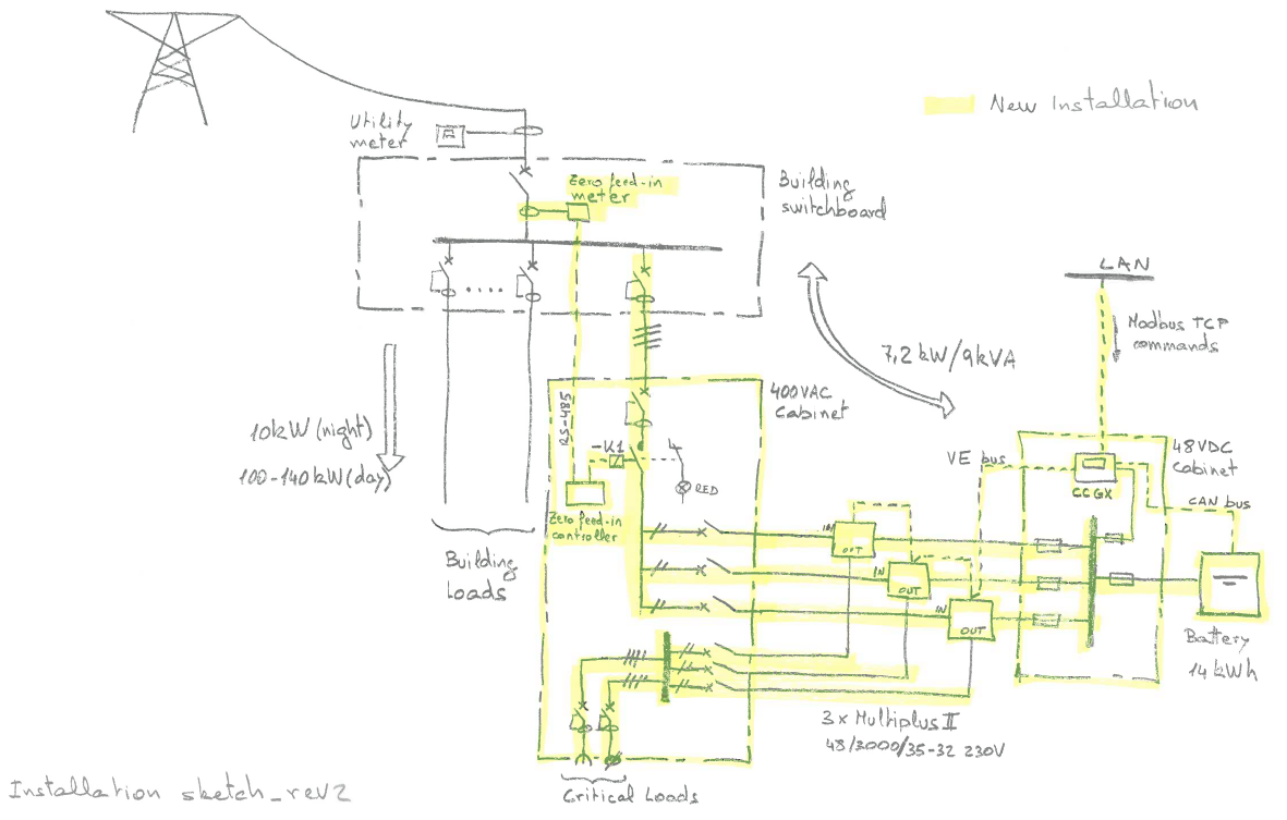
AC-OUT terminals will be idle, that is, although you can see some wiring and switchgear in the diagram to enable future connection of critical loads, this only would happen prior to reconfiguration of ESS to mode 1 (Keep batteries charged) for the multis to act as a UPS. Again, for the purpose of my question, no critical loads will be connected, AC-OUT terminals will be idle, and configuration will be in mode 3 (external control).
Contactor -K1 in the diagram will be governed by an INDEPENDENT system which will monitor energy going through a grid meter and will open the contactor whenever the power generated by inverters is being fed back to the public grid.
The thing is that I don't know how to size contactor -K1 in the diagram. I can see that sizing should take into account two cases:
a) When charging battery, I can assume that current will not exceed 32 A in any case, according to the Multiplus II datasheet.
b) When inverting, I assume that the maximum current through the contactor will be 3000VA/230V= 13 A. But my concern is that here the inverters are working as a CURRENT SOURCE rather that as a voltage source because they are following the Modbus TCP power setpoint.
Therefore, my questions are:
1. Could it be the case that the inverters "push harder" when they see contactor's opening? Would it be enough to put a contactor with rated current of 32 A (Utilization catetory AC-1) to account for case (a) or should I put a contactor with higher rated current (or harder utilization category) to account for case (b)?
2. How long will it take for inverters to realize that they cannot fulfill the power setpoint in the Modbus TCP map and stop trying?
3. Can this situation be harmful for the inverters?
4. In the end, which will be the error status of inverters? Will I be able to rearm them through Modbus TCP or only on-site?
Thank you very much in advance (and sorry for the length of the question).