question

geomz avatar image
geomz asked

Connect CCGX to SeeLevel N2K tank monitor interface

I apologize if I missed something already posted, but I’m trying to connect an N2K SeeLevel Tank monitor to a CCGX.

I am a bit confused as to what I physically need to facilitate this connection.

I have no other N2K “network” or system in place, and only have the CCGX and the SeeLevel (N2K enabled) controller head.

Is there a cable I can buy (or pinouts for a cable I can make myself) to connect these devices directly to each other?

There was a reference made by @mvader (Victron Energy)

https://community.victronenergy.com/questions/6170/rv-c-can-bus-tank-monitors.html

as follows:

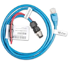
For clarity, the “Victron N2K adapter to which @ben refers is just a plug converter goes from micro-c n2k style to RJ-45 Victron VE.Can style.

No electrical components or software in there.


which makes me wonder if I can connect them directly??


Your help is greatly appreciated

Thanks

CCGX Color Controltank monitorNMEA 2000 - N2K
2 |3000

Up to 8 attachments (including images) can be used with a maximum of 190.8 MiB each and 286.6 MiB total.

4 Answers
geomz avatar image
geomz answered ·

I'm going to put the instructions below, on how I solved this problem --in case others are looking for the same information.
This solution relies heavily on @Kevin Windrem 's tankrepeater instructions (which is no longer necessary with newer GX OS versions).
It is likely quite simplistic for many on this forum, but I could not find one central place for this information, so hopefully it'll be useful to some.


Pieces required:

1) SeeLevel N2K control panel from Garnet.

Note: For some reason Garnet appears to no longer offer this on their website. But I understand that one can contact them and request a "prototype" version that they'd be willing to sell.
Their current solution is an RVC device, which will not work the same.

2) GX device. In my case, I'm using a CCGX.

3) N2K "network".

Note: I do not use N2K for any other system. To build a "proper" NMEA 2000 system requires a bit of hardware and wiring commitment, and I did not want to invest in that. This solution simply connects the CCGX directly to the SeeLevel tank monitor.

3-a) Scrap ethernet/UTP cable (cat-5 or better).

3-b) 3M 37104 plug connector.
Note: Kevin's instructions recommend a 3M 37104-2165-000 FL 100 connector, but with current supply issues, I could not source that, and ended up getting a 37104-2124-000 FL 100 connector instead. This connector is for thinner wire jackets, but worked fine for me. I sourced it from mouser.com and 3M makes several of these 37104 connectors for various wire sizes. Just make sure you stick with the 37104 series (4-pin connector). I'd also get 2 of them, just in case Murphy has his way.

3-c) 1/4 watt 120 ohm resistor. This resistance value is specific to how N2K terminates the bus.

3-d) The handy VE Can-Bus terminator doodad received with your CCGX (blue RJ45 terminator), that was probably tossed in a box somewhere long ago. If you do not have that, you'll need another 120 ohm resistor (see below).


To build the "network":

1) Cut off one end of the RJ45 ethernet cable.

Note: Ethernet cables are made of 4 twisted pairs of wire.

2) Holding the RJ45 connector, with the clip behind, and staring down at it, the pinouts are numbered 1-8 (left to right). Keep the wire pairs together and take note of their individual colors (to use below).
The 4 wires we're interested in are 3-6, 7-8, and we will use them as their existing pairs.
Note: The colors will vary depending on the spec used to make the cable, but in general pin 8 is solid-brown.

3) From the cut-off end of the ethernet cable, strip back the outer cable jacket enough to allow sliding the small wires firmly into the 37104 connector, leaving their individual plastic covers intact.
The 4 wires we're interested in are 3-6, 7-8, and we'll use them as pairs. Wires 1,2,4,and 5 should be trimmed off.

4) Holding the 37104 connector, position 1 is closest to the lock-clip, and is noted on the plug.
-- Place wire 6 (V+) into position 1
-- Place wire 7 (CAN-H) into position 2
-- Place wire 8 (CAN-L) into position 3
-- Place wire 3 (V-) into position 4
Note: There is no need to introduce external voltage into the cable. If you'll be using this setup with additional N2K equipment, you'd introduce power externally, and would likely use a dedicated power cable on the bus.
-- Insert the ends of the 120ohm resistor into positions 2 and 3 respectively to connect CAN-H and CAN-L together. This will introduce a bit of bulk to the connector, and depending on which 37104 connector you went with, you may need to strip the small wire jacket to make it fit. Or you may solder it on to the wires externally.
-- With all wires properly positioned, fully inserted, not crossed or touching each other, and the resistor properly in positions 2 and 3, press the connector end closed. Note: There is a special tool used to crimp that type of connector together, but I just used a set of adjustable pliars with a flat end to press it together.

By the end of it, you'll have one cable with a regular RJ45 ethernet connector on one end, and a 37104 plug on the other end.

Note: If you did not retain or have the RJ45 terminator mentioned earlier from your CCGX, you'll need to fashion a new one. A good way to do that is to utilize the cut-off plug end of the ethernet wire, and terminate pins 7 and 8 to each other with another 120 ohm resistor (trimming back all the other wires).


To connect it all together:

1) Plug the RJ45 end of the cable to either VE.Can jack of the GX.
2) Plug the RJ45 terminator into the other VE.Can jack.
3) Connect the 37104 plug end into the SeeLevel (with the side-clip, it only fits in one way) --and with the SeeLevel, of course, properly wired to its sensors and own power, etc.
4) Reboot your GX

If the wiring is correct, you'll see the N2K device show up, and likely 3 tanks connected.


Optional:

While creating a "permanent" cable might be the more elegant/clean/non-hackey way to build this solution, I actually created a less elegant version using an extra RJ45 wall outlet plug I had lying around.
You can buy those from Mouser or even Home Depot and the like. With it, I can use just a basic ethernet cable, and then do all the termination and break-outs of the cable into the 37104 plug separately using the punch-down slots on the wall-plug (each of which is numbered).
That way, the "wall-plug" is, in essence, a custom connector/dongle for the SeeLevel, and the rest is just basic RJ45 wiring.


Additional:

If you are running a GX OS version prior to v2.70-12, the GX will "bounce" from one tank to the next to the next. Kevin's tankrepeater solution solves that problem with some custom code to better handle multi-device data. But the current/easier solution is to update the GX to the latest firmware.
Once updated, you'll see 3 discrete tank objects on the device list of the GX

You will want to go through the SeeLevel manual for the N2K to configure tank sizes, alarms, etc in order for the tank info to better reflect your actual setup.
There is a capability in the GX to twiddle some of those settings, but not all.

The built-in GX panels will now display a new panel page dedicated to tanks, and the "Mobile Overview" panel will display the new tanks on the side.
Personally, I'm not a huge fan of either of those visual options. While they are very much functional, I much prefer the look of "Flow Overview" panel. For that, I used another of Kevin's great solutions called GuiMods. It not only adds the tanks to the Flow panel, but a whole bunch of other nice visual add-ons as well.
Instructions and installation source material can be found here: https://github.com/kwindrem/GuiMods

Good luck and regards,
GM

3 comments
2 |3000

Up to 8 attachments (including images) can be used with a maximum of 190.8 MiB each and 286.6 MiB total.

Kevin Windrem avatar image Kevin Windrem commented ·
All good except you don't want to connect the V+ connection. It might not hurt anything but the SeeLevel is not powered from CANbus.


I basically did exactly what you did and it works perfectly. A true CANbus implementation is totally overkill and extremely expensive for this application.

0 Likes 0 ·
lothmer avatar image lothmer Kevin Windrem commented ·

b27068bf-380e-412c-8c90-5d6ae78d7774.jpeg
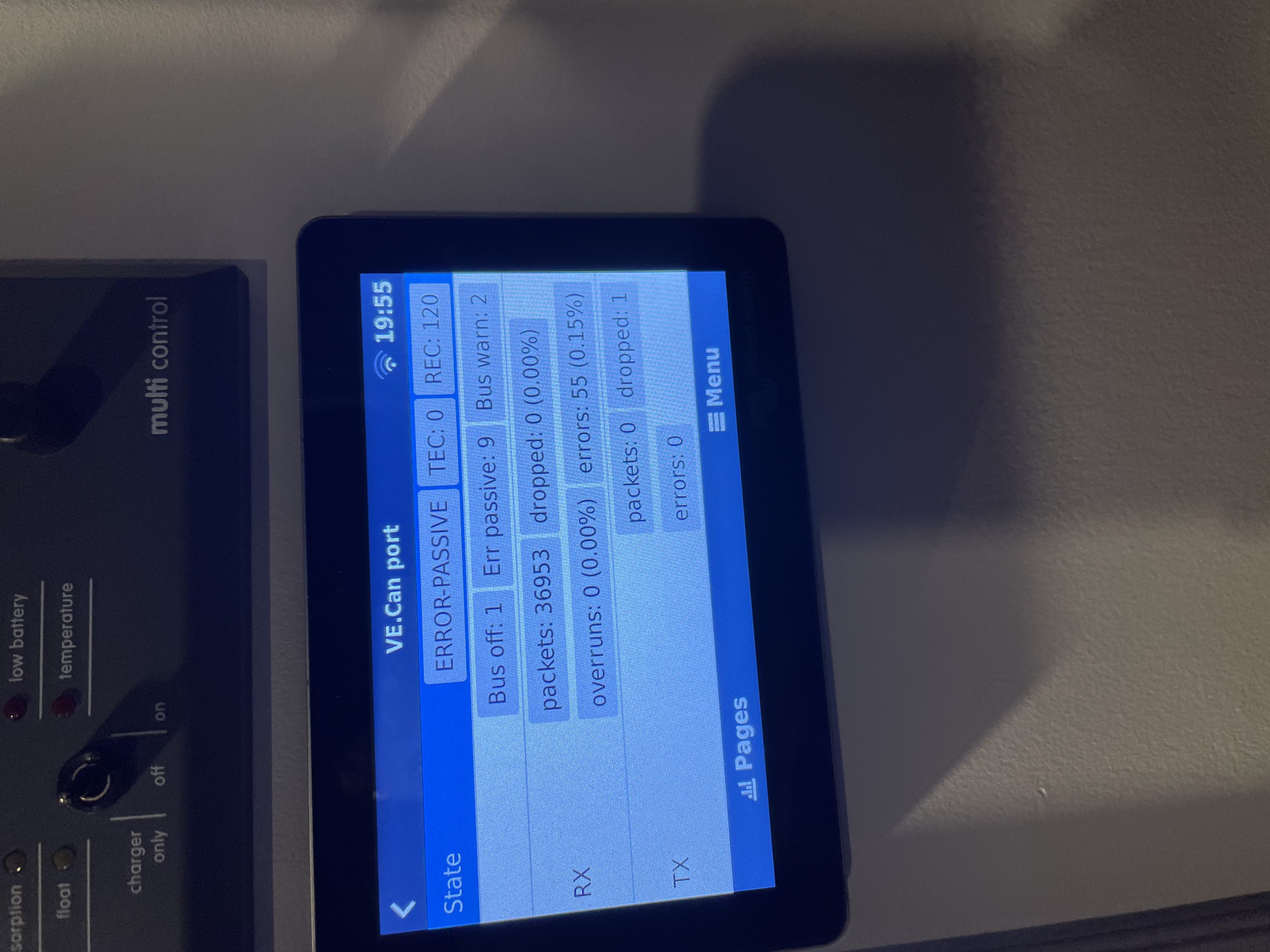
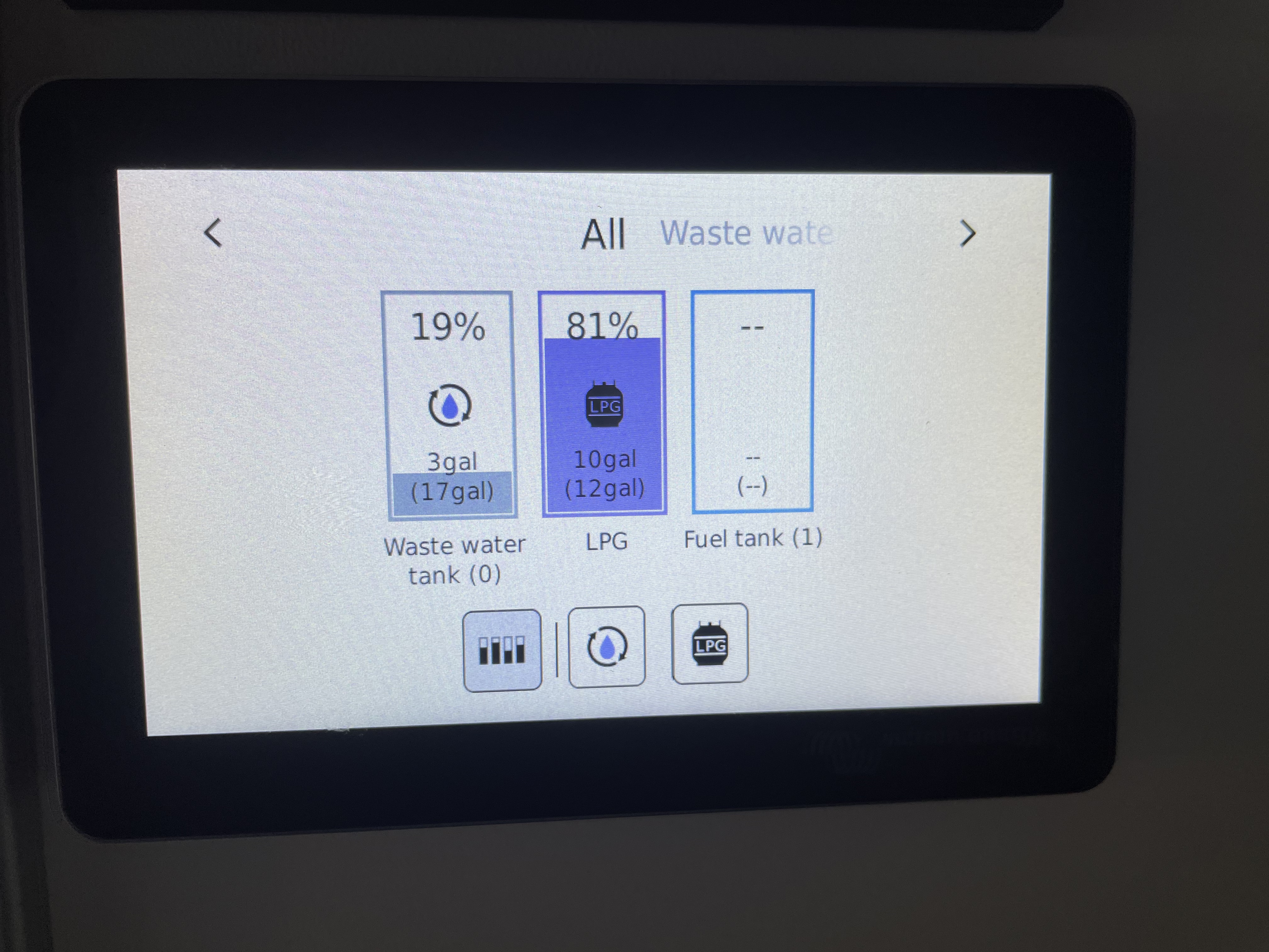
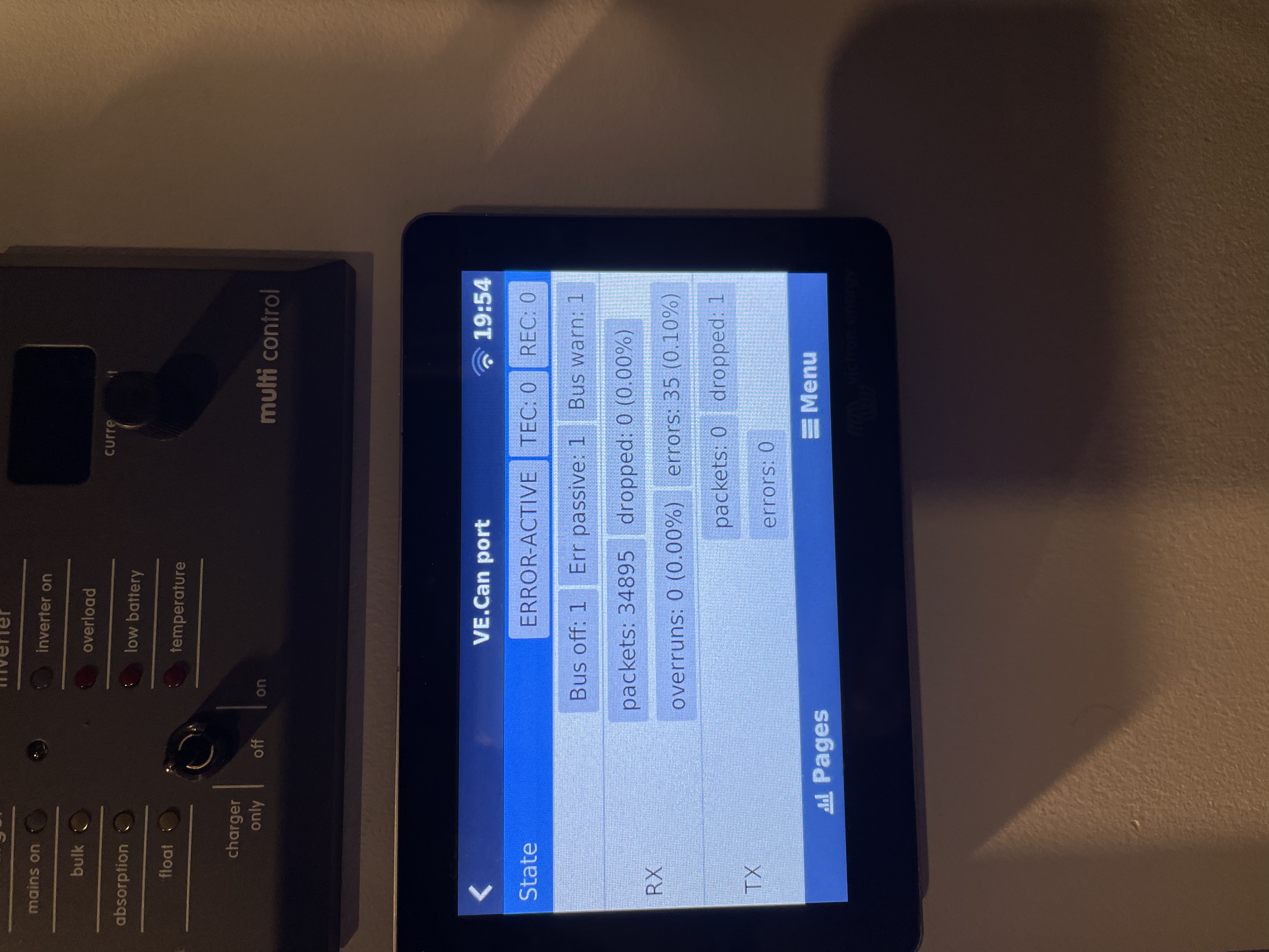
Hello, I followed the instructions above and the CERBO GX initially obtains the signal from the SeaLevel N2K for the water and grey water tanks but then loses the water tank reverting the display to “Fuel Tank” and then sometimes not showing it at all. I can repeat this issue by turning the power off and on to the N2K. Attached are screen shots of the CERBO VE Can port status showing errors. I’m not sure if the issue is with the N2K or CERBO. I’m grateful for any advice.b9e40c30-bc92-49a6-a178-18fd918eb0dc.jpeg

0 Likes 0 ·
lothmer avatar image lothmer lothmer commented ·

Here’s a photo of the GUI Mid tank screen.

0 Likes 0 ·
Paul B avatar image
Paul B answered ·

You will need to make a Can Bus Network. The example below shows two device connections, you can have as many as you want

Terminator to 12v power injector to a tee connector to a terminator the Device 1 connects to the CCGX and device 2 to the sealevel tank monitor you will also have to program the sealevel tank monitor with the correct fluid type as well I would think.

1624176491456.png


1624176491456.png (54.0 KiB)
2 comments
2 |3000

Up to 8 attachments (including images) can be used with a maximum of 190.8 MiB each and 286.6 MiB total.

geomz avatar image geomz commented ·

Thanks @Paul B for the answer above.

While I greatly appreciate the info above, I’m not really looking to implement a whole bunch of extra/thick wires to connect these two devices (6” apart) to each other.

A solution as above would require meters of drop wires, endpoint wire, ends, connectors, et al. Since I have no (current) use for canbus, beyond this situation, I was looking for a simpler direct-connect setup.

I know I can terminate one end of the CanBus with the CCGX rj45 terminator I already have. I can terminate the other end with a simple 120ohm resistor or another rj45 plug wired into the bundle

The tank monitor end will be an RV-C cable that I’ll have to cobble together anyway.

I would like to know the pinouts of the CCGX for can-hi can-lo ground and which pins to inject +-12v onto.

Thanks again

0 Likes 0 ·
Paul B avatar image Paul B geomz commented ·

Victron Supply a drop cable to do this VE Can ti nmea micro-c male ASS030520200 I do not know the pin outs, so suggest that you purchase the correct cable.

1624334413935.png


0 Likes 0 ·
1624334413935.png (67.2 KiB)
littiken avatar image
littiken answered ·

Resurrecting an old thread. I have a Cerbo GX, with Guimods in my Camper Van. The van already has a SeeLevel 709-HP3W system for reading the tanks. I'm assuming this control unit won't work with the Cerbo GX. It looks like both the 709-N2K and 709-RVC are now available for $229. Wish I had a cheaper option, since I already have the other control unit. With both of these available now should I just get the RVC unit? Will it be easier to wire up? Thanks for any help. Rob

4 comments
2 |3000

Up to 8 attachments (including images) can be used with a maximum of 190.8 MiB each and 286.6 MiB total.

Kevin Windrem avatar image Kevin Windrem commented ·
I don’t think there is any support for RV-C in Venus OS yet. V2.90 will have some RV-C support but reportedly to SEND information to MFDs. The N2K version is the one to use for now.
1 Like 1 ·
littiken avatar image littiken Kevin Windrem commented ·
Thanks Kevin. I may just wait for awhile with my current setup, and see what they come out with in the near future.
0 Likes 0 ·
Kevin Windrem avatar image Kevin Windrem Kevin Windrem commented ·
Mopka has ultrasonic Bluetooth sensors that work with fresh and gray tanks but not black tanks. Victron has been working on support for their propane tank sensors and I’m not sure if that will include the fresh/gray tanks. But without a black tanks solution ….

The reason black tanks aren’t supported is the possibility of build-up of solids above the sensor.

There are also some pressure sensors that might work with the GX tank adapter (voltage and current). Plus a bunch of float activated resistive sensors that work with the Cerbo tank inputs directly. The float sensors mount through a hole in the top of the tank so not a great solution if your tanks are mounted under the floor.

0 Likes 0 ·
littiken avatar image littiken Kevin Windrem commented ·
Thanks for all the great info Kevin. Much appreciated.
0 Likes 0 ·
jamesmcclatchey avatar image
jamesmcclatchey answered ·

I have successfully implemented the connection from the SeeLevel N2K display to the Cerbo using the VE.Can network. One glitch was that initially I used a Cat6 cable 25' long to connect the SeeLevel display in the kitchen of a 27' Airstream trailer to a front storage area that contained the Cerbo GX. That connection was unstable. I read somewhere that 25' might be the limit of the N2K connections. I replaced the cable with a 30' Cat 8 cable as the 25' cable was only barely long enough. The thicker wire even at additional length solved the problem.

Another tip that might be helpful. I tried putting the resister leads into the Mouser connector, but I had difficulty making the leads stick. I instead used a 3 Way 2 Pin Small Wire Connector, Compact T Tap. This worked much better for holding the resistor leads firmly. https://www.amazon.com/dp/B08C9QWTG8?ref=ppx_yo2ov_dt_b_product_details&th=1

Finally, because I was working in a tight space, I made a pigtail 6 inches long with an RJ45 plug on one end and the resistor T Tap and Mouser connector on the other end. Then I used an RJ45 Female-Female connector to connect with the Cat 8 cable. This enabled me to work on the connections that needed a fine touch out on a table and not while trying to hold the Cat 8 cable in mid air which already had RJ45 plugs on each end.

My only complaint now is that I am not able to edit the names of the tanks. I have GuiMods and can change the fluid type but not the uninformative Tank 0, Tank 1, Tank 2 names that appear in the Cerbo Device List and on the VRM portal. I hope this is something that Victron will take a look at. They did the work to make these connections possible. It would be a further improvement to make the names editable.


5 comments
2 |3000

Up to 8 attachments (including images) can be used with a maximum of 190.8 MiB each and 286.6 MiB total.

Kevin Windrem avatar image Kevin Windrem commented ·
With terminations at both ends of the cable, I ran 200' of CAT6 from a CANable CANbus interface to my SeeLevel N2K. Comms were stable. CANable has a built-in termination. The SeeLevel does not.
1 Like 1 ·
jamesmcclatchey avatar image jamesmcclatchey Kevin Windrem commented ·

Interesting. Perhaps there was something else wrong with the cable I used although it was a stock ethernet cable. It was very frustrating as I had to run the cable a difficult length a second time.

I was going by this info: According to the NMEA 2000 standards, the maximum length of a drop cable is 6 m. However, it is always best to use the shortest drop-cable length as possible.

https://www.bandg.com/en-GB/help--support/?guideTitle=How-to-Design-and-Build-an-NMEA-2000-Network&guideId=003-779

0 Likes 0 ·
Kevin Windrem avatar image Kevin Windrem jamesmcclatchey commented ·
I needed to connect the ground connection as well as the two data connections to get this to work even with short distances. My CANbus interface is floating/isolated. I believe Cerbo is NOT isolated so it may have worked without the ground but might work better with the ground connection also. Although grounding this might create ground loops and make things worse.
0 Likes 0 ·
jamesmcclatchey avatar image jamesmcclatchey Kevin Windrem commented ·

I took a closer look at the faulty ethernet cable. I think in connecting to the Mouser connector, I inadvertently cut into one of the wires (green/white), That was probably the problem. I was working on this with the cable poking out of the wall of the trailer. Hard to see and hard to access. The separate pigtail with an RJ45 socket on one end and the Mouser connector on the other than can be worked on a bench with good light is the way I went later. Much easier to work on if there is a problem.

Still would advocate for a Cat8 connector as best practice although not a necessity.

0 Likes 0 ·
Kevin Windrem avatar image Kevin Windrem commented ·
I'll second the need to name tanks from within Venus OS. The notion that the sensor should supply the name is good in theory, and I've heard that some sensors do supply custom names. However as users of SeeLevel know, this not possible. Showing the same tank info on multiple devices could show different names but if all display devices support local names then this is a matter of a one-time system configuration task, then everything shows the same names.
1 Like 1 ·

Related Resources