Hello.

I installed a new Mulitplus 2 48/5000. DVCC limit charge current does not work. With the old Quattro, DVCC worked without any problems. Did I make a mistake somewhere?

System setup:
ESS with Cerbo
MPPT chargers show "external control".

greeting
Paul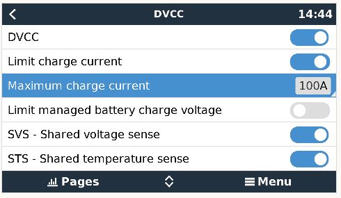
asked
DVCC limit charge current does not work
Do feed in from DC? Then this is documented and normal behavior.
See https://www.victronenergy.com/media/pg/Cerbo_GX/en/dvcc---distributed-voltage-and-current-control.html#UUID-ab5f5267-b5d7-d9c2-40f1-8dde56821752
Note: When DC-coupled PV feed-in excess is enabled with ESS, the DVCC system will not apply the DVCC charge current limit from PV to battery. This behaviour is necessary to allow the export. Charge voltage limits will still apply.
If this is supposed to be the designed behavior, then there is a catastrophic error, because the CCL is also ignored by the BMS during tests and if the BMS requests a different charging current, then the system must follow this, otherwise the battery will come into a critical state.
Hi @mvader (Victron Energy): this is a serious and recurring bug that should imho get your attention. As northern hemisphere moves into summer and feed-in excesses are more frequent, it becomes a security issue. DC CCL should not be exceeded for long times (in my case it was for >5 minutes before I stopped this).
When DC feed-in is enabled, VenusOS can't just close the eyes on DC CCL and only check for DC CVL. Such cases where PV power exceeds feed-in limits or total maximum inverter power or inverters don't react fast enough due to e.g. grid code, should be handled.
I stumbled over the same issue this morning. CCL set to 60A but 150A charging happening.
- CerboGX with latest release
- Pylontech CAN connected battery bank.
Is is a real worry...
@Mark Maritz I assume that you use MPPT's, right?
In that case only an external dynamic voltage regulation helps.I implemented such approach via NodeRed (see: https://community.victronenergy.com/idea-comment/142008/view.html and https://community.victronenergy.com/idea-comment/142432/view.html).
I have a mixed Inverter/MPPT environment. CCL does regulate inverters, but not MPPTs.
Thanks
@ThomasW. I will look into this - I use HA and Node Red for other things...
Hi @Mark Maritz,
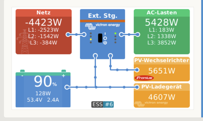
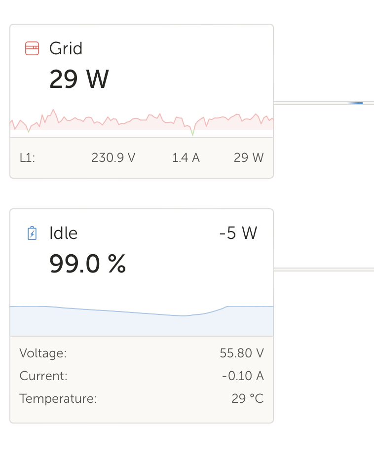
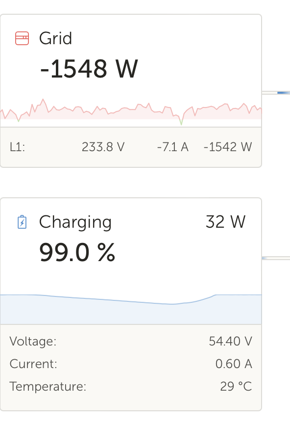
see below a live copy, where you can see that such approach works.
SInce the regulation has to deal with voltages, a wrong setting application could lead to a collapse of the battery. My application now is life for >1 year and works reliable.
The note of "ESS#6" indicates the current voltage regulation.
Hi @thomasw-1 , that approach looks really nice (read your other thread you referenced) and is imho in all cases safer than Victron's one, where no battery CCL is respected when in DC grid feed-in mode. Internally in MPPTs and anywhere, current limitation implementation is done with voltage or time-cycles control anyway, so it's a similar approach, just globally in VenusOS controlled by your nice NodeRED script ?
Normally, the BMS voltage limit is always respected independently from the DVCC voltage limit setting.
So I don't see any way to damage the battery more with your script than with Victron's standard implementation ?
Victron's standard DC grid feed-in implemenation keeps the MPPTs at maximum power and doesn't control properly the inverters/multipluses. This results in massive overshoots of the battery's CCL including at the battery-life-and-warranty critical almost-full or already-100%-full state until the DVCC voltage (or battery's BMS maximum voltage) is reached.
Am I right in my analysis, or do you see any other possible damages of your script that could be worse than Victron's, given that VenusOS will always enforce the BMS maximum charge voltage indication ?
For sure there is a way to damage battery. In case voltage is selected too low, battery would be fully discharged even by very high currents, with a too high voltage the battery would be grilled.
In the beginning of my implementation I had a selector, which allowed an ad hoc voltage adjustment. An unconscious change led to the cirumstance of a heavy discharge (energy was fed into grid). Luckily I received a VRM notification, so that I could stop the situation. Since then I allow in configuration options only a minimal adaptation range.
In addtion I assume that different batteries have also different characteristics. Therefore the initial adaptation must be also applied with special attention and care. This is also the reason, why I share my script only if a liability disclaimer is agreed.
Btw. currently I do not use my script to limit charging currents primarily (could be a later option), but to limit die SOC to a predefined maximum (currently 90%) with background of extending battery lifetime.
In principle also the current could be influenced during overall charging process as well. Since GX only allows a voltage definition with a 0,1V granularity, only a rough setting is possible. This is also the reason that I align the battery energy flow to absolute 0. Either I have a slight discharge or a slight charging (20-300W). I prefer last option, since I consider that a bit more polite to my battery.
Ah, better understand your caution. However I don't think that the too high voltage would be allowed to be higher than the maximum charge voltage of BMS, which is applied in all cases, also with grid feed-in. A lower maximum battery CHARGE voltage change (even with an erroneous input by a non-specialized user) should imho not lead to heavily DISCHARGING the battery to that voltage ASAP. That should imho be classified by Victron as another dangerous bug...?
Maybe open a new topic for this where you can detail your system.
Do you mean the CCL pylon is sending to the GX is 60A or have you manually set it lower in DVCC?
DVCC will always try honour CCL, and for supported batteries it should work.
Also, provide some supporting charts for the battery limits, V/A etc.
It is a misunderstood issue. Something that should not affect a supported and tested battery. Not unless something else is going on.
Here is another fully charged, supported battery. CCL honoured under export..
Before:
After:
There is an initial transitionary period, but after around 30 seconds or so, it settles.
There is NO issue once the maximum charge voltage is reached.
The issue is before that. We agree that a battery can whistand a few seconds of limitde overcurrent (and it's even in the battery's specs).
The heavy overcurrent compared to battery specs and BMS current limit often lasts for more than 5 minutes, which is a real problem: Actually, it lasts until the maximum charge voltage set in DVCC (which is also limited by the BMS max voltage)) is reached:
Only then do the inverters/multiplus start to feed the extra DC-MPPT's power into the grid. The issue is that this grid DC feed-in of extra solar power seems to be an on/off state. I have not deep-dived into the code, but that might be a bug in the Multipluses, a bug in VenusOS, or a system design bug.
We see similar on/off instead of gradual design decision for the "Minimum SOC" ESS feature: When there is not enough PV power to power the loads, there a heavy charge/discharge cycles going on around minimum SOC. I could manage that part by setting grid setpoints (without DC grid feed-in set!).
While this minimum SOC ESS design bug is annoying for battery life, it is not dangerous.
But ignoring the battery's CCL and the DVCC CCL with DC grid feed-in can be dangerous (and is only safeguarded by the battery's internal BMS). And it's definitively shortening battery lifetime, and potentially voiding the battery warranty.
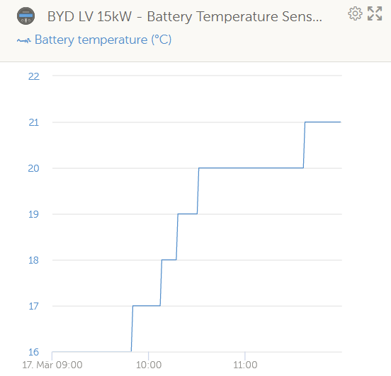
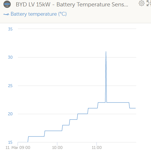
The difference is quite simple. With a contolled CCL the temperature increase of the battery is minimal, whereas without it can be tremendous (in previous test up 45°C) - examples from recent days below.
According to official studies that issue reduces battery lifetime. See my separate posts related that constraint, but please don't start an additional discussion about that topic - I evaluated sufficent scientific studies arorund that tropic.
with control (5°C temperature increase):
without control (16°C difference - real peak might have even higher):
That wasn't at maximum CVL. Some here are comparing apples to oranges. Without knowing what your battery is, how it is sized and configured, all behaviour is being conflated together to be a DVCC issue, when I would argue it is a battery/implementation issue.
Victron clearly state it is bad practice to manage battery charge by setting CCL=0, yet that is what many do. They also want a variable CVL, something mine does, but others don't.
For the 10's of thousands of installs, it tends to work. When there are exceptions there usually are good reasons for it, and often based on interesting design choices.
I will leave it there, no need to keep flogging a dead horse.
It works as designed and as documented.
If you are the exception and not the norm, not much any of us can do about that.
I agree!
I did put in a "feature request" via the Modifications space a long time ago, with no response or indeed very little comment?
https://community.victronenergy.com/questions/193988/ess-grid-feed-enable-when-soc-100.html
@nickdb : it is not about CCL reported by battery, but about CCL that can manually defined in DVCC menu (as title of this thread)!
This I am aware of, and have stated numerous times.
For a supported, managed battery, there is absolutely no need to manually limit the charge current.
That affects niche cases, generally custom or DIY implementations. Which by definition tend to not be supported.
If someone chooses to overrule the BMS, then you can't be annoyed when documented behaviour does what it says,
For the majority of people, it works as intended, without issues.
Hi,
Is it a momentary spike, or are you seeing sustained charge currents like this for long periods of time (minutes)?
I waited 5 minutes. The charging current remains constant at the maximum.
Do you mind if I have a look at the VRM account?
What is the site name?
Hi
Did you found a solution? I expected also with feedin activated, that if the max charge current set was reached (either from DVCC/BMS or set value in DVCC menu), the Multiplus would take over and feed into grid. And if Multiplus were not able to feed enough into the grid i.e. due to high temp or grid restrictions, the MPPTs should lower the charge current (as it does for feedin deactivated or if CVL is reached).
BR,
Lars
Hi Guy,
Today I performed a test on the "Limit Charge Current" feature. In my configuration I have an AC-OUT attached 3-phase Fronius inverter (6kW) and a DC-attached Victron MPPT (5kW). Battery is a BYD LVL, VenusOS on version 2.72. Setup as 3-phase system.
After having set the charge current limit to a very low value (e.g. 10A, 5A or 0A) the Fronius inverter power got fully redirected instead to battery into grid. However the MPPT continued pushing all energy into battery. So the MultiPlus-II did not invert that energy and directed that into grid as well. MPPT shows "External Control", so it should be actually under control of DVCC.
Since @user0815 uses MPPT only, the route cause could be identical.
So the feature did not not work as described in DVCC manual: "If a CANBUS-BMS is connected and the BMS requests a maximum charge current that is different from the user-configurable setting, the lower of the two will be used."
Any advice?
What is set as battery monitor in DVCC?
BMV-712 set as battery monitor
Hello ,
I have the same problem with my DVCC Limit charge current settings.
i set to 70A , both solar chargers work well with 70A maximum charge current to the battery, but if I turn on the main Grid power to the Quattro inverter, the battery charge current is more than 70A.
Can you help please?
victron system
Same issue, any solution to get the MPPT to respect the DVCC Charge Limit?
OK, Thanks,
Is there a way to disable all charging from AC & DC and Invert all of the MPPT Output? (plus export any of the AC-coupled PV but that is Independent and will happen anyway).
I have the same issue, DC current limit in DVCC is not respected (Pylontech US3000C BMS). I have DC PV excess feed-in (single-phase for now), but also an ESS export limit active. It looks like the computed PV DC current does not take into account the ESS export limit. The BMS charge DC limit is (most often!) respected. This looks like an annoying bug, as it shortens the battery life.
Hello,
Not 100% sure with my "reaction" here .. but will try to share the guess and opinion.
Yes it looks like a trap.
When having the "grid feed-in enabled" that as said is (for some reason) switching the "MPPT regulation" off - (somehow like "risky" or "hard to solve" to make it regulated ?? - or avoid up and down cycling between "limited MPPT" and thus "not feeding all possible" ???) (It looks like once someone decided not to limit the MPPT with feed-in enabled and since then no arguments have changed this - or the physics? Next block.)
Or is it just about this 0.4V the MPPTs "up" the voltage when "feed-in" is allowed? (SORRY if I am mixxing two things.. and the 0.4V which could a bit expain "nature causing problems here" comes from other things ..)
And then someone "has to take the current coming with higher voltage away from the "VE Bus" ?? (as when on "normal Voltage" the additonal current from the roof does not flow .. when there are no valves open - just a guess..)
The "trap really closes" when you limit the "Feed-in" - then the "unlimited MPPT" is pushing against the "limited Feed-in". (or in my actual case - against the "feed-in initiating Multies, but crap slow (do not why ...) and the battery nearing to end of the charge limiting its demands" - but because of "feed in allowed" (and pretty high limited - should not be problem in the limit in my case, just in the "feed-in enabled checkbox") - the MPPTS just "push the max" because.)
Of course not aware - what "may be harder" on variable MPPT output without feed-in and with feed-in enabled. (independent on the feed-in limit then - which would affect the "variable MPPT" as it does also the "real consumption".
Somehow with "feed in disabled" MPPT is delivering "the needed for loads(and battery)", with feed-in enabled - the MPPT could deliver "the needed for loads(and battery)" + `feed-in possible at the moment" (also respecting the feed-in limit .. ) Which would change, when the multies feed more and more over time (guessing some grid ramp-up limitation..) or loads start/stop .. which all works "just when feed-in is not allowed".
Someone hates feed-in? Or is the result/availability of feed-in less foreseable like a huge load on/off or really something in the physics?
(Simple to write, maybe not as simple to implement ... or otherwise wondering why this (variable MPTT output) and also the for me newly published "feed only critical loads from battery" features have that kind of "both see the red flag when feed-in is enabled".)
Feed-in enabled
- causes Batery high alarms - when on end of the charge cycle
- causes issues when feed-in limited
- disables the "feed only critical loads" feature in 3.1 ESS (or somewhere there)
Joke at the end - lucky me, would I have only like single phase system and huge roof for "winter time" .. the enabling of feed-in would probably force me to build a new house or tent because of explosion.
@beat - about the 0.4V (described in my prior comment)
From the GX device manual pdf :
8.6. DVCC for systems with the ESS Assistant
A fixed solar offset of 0.4V is used instead of a variable 2V. (values for 48V systems, divide by 4 for 12V). Note that this solar
offset is only applied when ESS-mode is set to Optimized in combination with the Feed-in excess solar charger power-setting
enabled, or when ESS-mode is set to Keep batteries charged.
It maybe does not specify that the MPPT is not "throtlet" explicitly - but the wording "sounds so" :
ESS design and installation manual
4.3.5. Feed-in excess solar charger power
Set to 'On' to make the >>>> solar charger always operate at its maximum power point <<<<<<. The first priority is powering the loads, and the second priority is to charge the battery. If more power is available when those two priorities are met, then that power will be fed to the utility grid.
Please note that when enabling this option, the DVCC charge current limit configured under Settings → Limit charge current won't be active. The solar charger will operate at full power for maximum feed-in into the grid. It's advisable to configure a safe limit on the solar chargers when used with a small battery bank.
End of document "part" ..
And here my "thinking" - thus when the MPTTs or maybe other parts of the setup (but I guess only MPPTs) are set for +0.4V higher when there is the feed-in - this higher voltage push is applied independent on the full battery, feed-in limitation - and in my humble opinion - here we have the cause - where there the "surplus energy" comes to the ESS system - and does not get out.
As for the "lazy multipluses" in my case to ramp up the feed-in fast enough when battery goes "almost full", also for the "limited feed-in" or in other cases for the "limit charge current" (or something similar).
Idea only : It looks like that when you enable the feed-in - the "add-on" solution for the "standard and high probably very serious Victron setup" was to raise the MPPT voltage with 0.4V to "heavily push the energy" through the system. And that is then causing issues when there is either small load, or people try to limit the fee-id (or have to limit the fee-in) or users or the battery "try to limit the charge current". It is like "is there nobody to limit the energy from the roof??".
Amateur conclusion : nobody said to you it would be better to not have huge DC connected MPPT/s, but maybe setup some AC like Fronius (which will throtle via frequency) for the majority of the solar energy - because of as it seems lack of regulation when feed-in is enabled.
@rogio It is said in all Victron online trainings that for direct AC use and feed-in, it's much better to have AC inverters than DC inverters. DC inverters are better at charging batteries, and a small one is needed for black startup without grid.
Additionally, I sadly discovered (but that's another issue) in an official Victron doc somewhere on this forum, that MultiPlus II are not that efficient at higher loads (the specification tells a "maximum efficiency 96%", so I was expecting from the spec sheet, like 92% at full power, and at very least 90% efficiency on whole power range, like most AC inverters, but it's over 90% only at lower loads and at 100% load, efficiency is around 80%, generating a lot of heat/losses).
But because of the 1:1 rule, you can't have more Fronius on AC-OUT than the MultiPlus power (and on AC-IN side, they are not contributing when there is power-grid loss). So for larger PV installations, always first put the maximum on a AC-OUT Fronius, then what's left on DC (not too much), and if there is till PV left, add a second AC inverter at AC-IN. Then plan a cable-management layout, order and manufacture all the cables, channels, and install everything on a wall, and have a large regulatory inspection.
I really hope Victron will fix this over-current bug, because it will allow it to sell more Victron gear and to simplify installations.
There are many many threads on this!! Unfortunately it is a fact from the ESS manual:-
Note: When DC-coupled PV feed-in excess is enabled with ESS, the DVCC system will not apply the DVCC charge current limit from PV to battery. This behaviour is necessary to allow the export. Charge voltage limits will still apply.
Charge current limits set at the individual solar charger device settings level will also still apply.
I've also the same behavior and see a big issue by an over charge current if the CCL requested by the BMS is ignored (alos if it is set manually within DVCC).
If the BMS requests an lower CCL in case of an over temperature or cell inbalance it is importend to lower the charge current to prevent system fails and to achive optimal performance.
@Victron Support: Please provide a solution or inform if it is on-going.
My experience - having the BMS (4xPylontech US300C - the corona series) lowering the charge curent limit it looks like the Multipluses II 5000/70 48V take even 5+ minutes to react and to initiate "serious feed-in" - and during that time the almost "full" battery ~95% SOC goes into "High Voltage alarm" based on cell imbalance - like 6-10 times in a row.
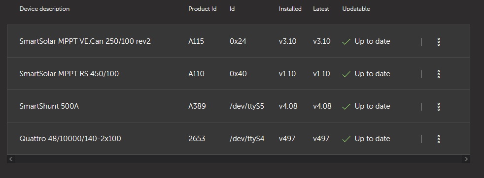
(3 phase system 506 firmware, cerbo ESS at 3.10 - recently upgraded by local importer support - as non-working try to avoid this.) While the three MPPT regulators do not limit the roof (as they according to the documentation should not (sadly as they could be bit more reactive than the Multipluses).
Not a new battery bank, half year in use, problems appeared since enabling feed-in. It looks like based on the LOM, or country code related requirements, the ramp-up of feed in is in like 600W steps taaaking looong minutes, while the almost full battery "suffers" 2kW plus (kind of the pain limit) - sometimes way over the requested Amp limitation - Multipluses still minutes behind. (and because of the settings the regulators stay at full). Standig in front of choice - disable feed-in (and loose money), or let the battery suffer (and loose money and theoretical varranty) - none of them is good.
Somehow - when the battery already requests like 2nd, 3rd step of lowering the charge current (I mean for 2nd, 3rd time already below the actual one, already few steps away from the initial 148A), the Multipluses start to react for 1st time - already minutes too late (and continuing in that - still staying behind the battery few minutes old requirements)
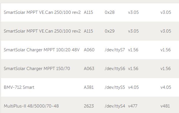
(SmartSolar MPPT VE.Can 150/70 rev2 v3.13
SmartSolar Charger MPPT 150/45 rev3 v1.61
SmartSolar Charger MPPT 150/35 v1.61
External grid meter ET340
Feed-in enabled, limited to 7kW. Czech "mess" with "individual phase regulation"))
Two pain-points somehow during the half year of end-user Victron ESS+Pylontech experience - having now in the sommer-end the feed-in enabled - getting the "high voltage alarms".
And one older - during the March/April times - crappy experience, where when the solar was lover than consumption then "high" part of the solar production was pushed "through the batery" - meaning - battery on SOC, got charged with solar (it was not used for satisfying part of loads requirement - as the docs say .. just the bat was charged .. ) and when 10% of "minimum SOC" above "minimum SOC" .. the battery and solar were for some time feeding the loads .. and the same repeats - charging and discharging the 10% of minimum SOC and using the grid for feeding loads while charging battery. (Where docs are saying "loads first" - not really, charge and discharge of 10% of minimum SOC in battery capacity seems to be the primary target. (charge/discharge loses and batery cycling as a result. Example - 300W solar, 600W load, 30% min. SOC unless grid fails - ESS#1, ESS#2 - solar charges battery to 33%, then the 3% and solar are used for running the loads and repeat.
I can confirm both wrong behaviors you are describing on my testing-installation.
1. Overcurrent:
I have limited DC voltage to 52.3 volts in the DVCC settings (this one is respected and imposed to MPPTS) and to 52 volts in all MPPTS and in the MultiPlus (not respected, as in External Control mode, but it's a safeguard in case one day external control would be lost), and at least that got me rid of the overvoltage alarms - at the expense of slower charging in the last few percents of the battery (but that's actually ok).
I did not even need to change current limit, but just on AC1 OUT1, a high load suddenly switched off, and the solar input would not lower for minutes, and excess current goes into battery, charging many times over current limit.
This issue with solar not adjusting fast enough is a big problem, and subject of this thread.
2. Minimum SOC handling:
That's imho a different problem. You should probably start a new thread for it.
The minimum SOC handling is quite "stupid", cycling the battery around minimum SOC. At just above minimum SOC with 300W solar and 600W load, one would expect that 300W would go to loads, and nothing to battery. That behavior is "just" loosing the battery round-trip energy and aging the battery.
@beat Thank you very much for your fast and informed reply and advice.
1) Will try to suggest that to my installer as also to the local distributor (who to my surprise went beside of other tries into setting higher current value here of 55 (which is luckily ignored by ESS/DVCC) - before not taking phone calls).
As I have still somehow "the strange feeling" not to touch the installation (the core parameters) still being in warranty, .. and not to update the serious config values "together" or "against the tries" of the trained persons (installer and local reseler technician). Had already some argument with installer "not to change the configuration" - which I did not, but he suspected me at some point in the past. (Thus somehow "sitting around with bound hands". Having external anti-islanding device installed (grid provider requiement, independent on the device capabilities), so the LOM could be switched off for testing purpose, .. the voltage could be updated (here I hope the "hardcoded Victron Pylontech battery handling in ESS/DVCC will not overrule"), but have to wait for the cotact success/reaction/end of holiday.
This is a bit the tricky area of "who should be the administrator" - the installer or the consumer. And where are the borders. (Where yes, in respect of stuff like LOM, ... it seems to be the installer for sure - and I understand the password barier there (I know it is on internet, but as it is there - it has a reason to protect lifes.)
2) About this "cycling" have I seen some (pretty old and for year/s cold) posts here, somehow taking my hope to reach something with raising a new one. From my installer I have got the "statement" of local resealer that this behaviour "is standard". Still scratching my head - how can be, that the documentation is saying "consumption first, battery seccond" - when you then see that the battery is on low minimum SOC, solar production is lower than the loads - and for some reason the ESS "chooses" to charge the battery a bit (10% of the minimum SOC) up (above the minimum SOC !!), to discharge it at SOC+10%SOC again down to SOC .. and run this the "whole semi-dark day". (as you formulated it pretty nicely - loosig the battery round-trip energy and aging the battery - exactly. Just wasting the power and battery.) (btw. load first, battery 2nd - is also broken by the "with battery-life" setup imho. (kind of strange too...first charging the battery before going to share the solar with loads in the morning. Thought about it a bit different - that it will only protect the "dynamic minimum SOC" - but looking at the recent data says different things.)
Both this behaviour - with "External control" of the BMS - looks like "anti-battery focused behaviour" - overcharging the cells while ignoring the current limit drops requested by the battery (or ramping up grid feed-in for ages .. and not even limiting the DC connected MPPTS in case of "known timing issues" while the grid feed-in is enabled - yes, this "non-reaction" is documented), as also this "feeding in some cases even more than 1/2 of the solar through the battery first".
@PV-Andy @rogio, for the excess charge current at high charge states issue only (rogio: your issue #1 above):
Did you link the MPTTs 450/100-200 with VE.CAN or VE.Direct to your Cerbo GX ?
If you linked them with VE.CAN, and if you have enough VE.direct cable(s) for all your MPPTs (no VE.CAN), it may be worth a try linking them all with VE.Direct and see if it changes anything ?
I had done a very quick test and it seemed to not fix it, but maybe my test was too fast. And I can't test it more carefully on my test installation right now as I don't have the solar and load conditions now to reproduce this bug.
But as from what I saw in VenusOS, possibly these two interfaces are very different regarding external charger control parameters (voltage and current). And this could possibly have a significant influence in this issue. So worth a try.
Of course, before that, upgrade first your firmwares using VictronConnect for MPTTs and in the Cerbo GX to latest ones, so that latest VE.CAN and VE.Direct protocols capabilities are used.
@beat : Good idea, I've connected one MPPT 250/70 via VE.Can, one MPPT 150/35 VE.Direct and a AC PV Inverter ond AC-In of the Multiplus.
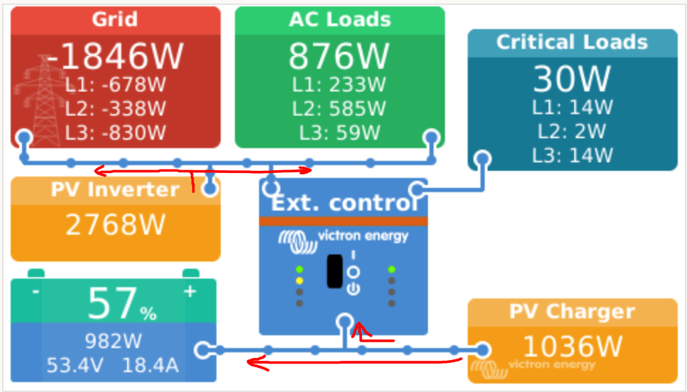
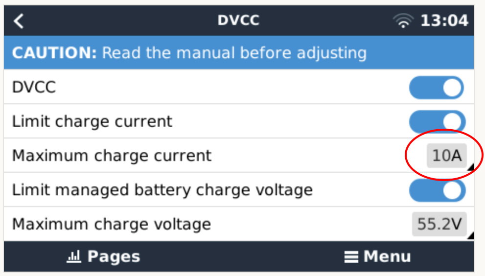
I've disconnected the 250/70 from the system and set the CCL to 10A, but the Multiplus stops only the charging from the AC-PV Inverter. The full current from the MPPT flows into the battery, but the Multis has to ramp up the feed in power to reduce the current into the battery.
Or in case of emergency the MPPT has to reduce the charge current to prevent harm the battery.
If the Multiplus is set in state "Off" (disconetc from Grid) the MPPT respects the CCL and reduce the current.
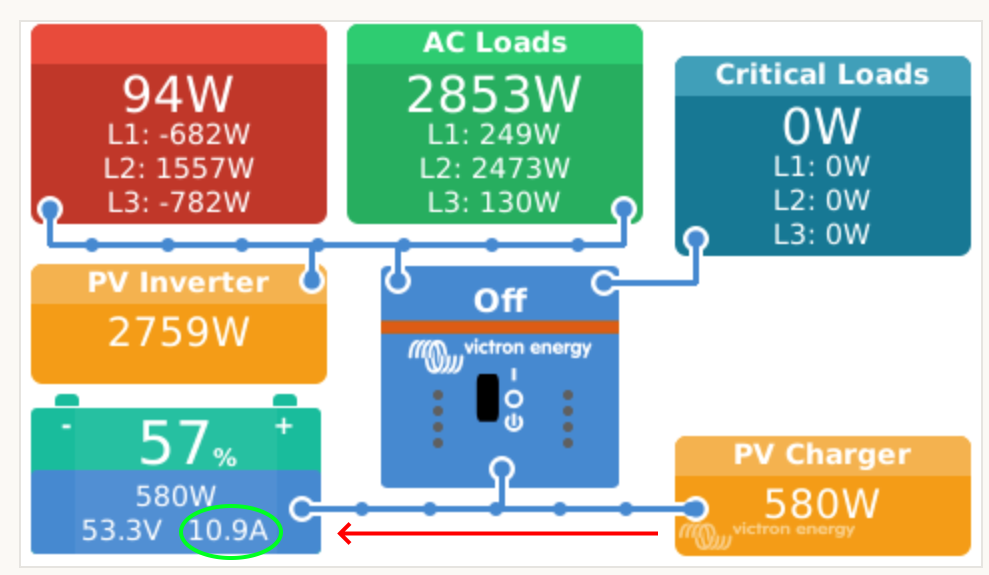
This behave in my opinion shows that the problem is in the ESS Assistent and the Multiplus dosn't ramp up the grid feed-in to reduce the chraging current into the battery.
My system configuration:
3x Multiplus 2 5000 (3 phase)
1x AC PV Invert connected on AC-IN
Cerbo
1x MPPT 250/70 connected byVE.Can
1x MPPT 150/35 connected by VE.Direct
Seplos BMS connected by BMS-Can
PV-andy, I respectfully disagree. The inverter cannot control what DC goes into the battery from PV, mainly because the MPPT's out voltage, and thus battery's in-voltage, is controlled by the very same battery's BMS.
The BMS sets the DC voltage, and the MPPT obeys, and is the only device that can control the DC voltage. The inverter is not authorized to command the MPPT to lower the DC voltage to prevent current going into the battery. The inverter also has no control over what current the battery draws/takes in a DC coupled, battery BMS controlled system, and the inverter can only take what is left after the battery had its fill, I believe. The BMS, standing guard at the entrance to the real battery - the cells - controls what goes into the battery cells.
When there is an AC coupled inverter in addtion to your DC coupled inverter/charger, and this AC inverter can be controlled by frequency increases decreases or some communication protocol, that AC PV inverter can be commanded (by the battery BMS, translated by the DC inverter or via comms) to limit the power put onto the AC circuit, and in turn, your DC inverter, which now functions as a battery charger for AC to DC, can control how much DC current is passed through to the battery.
@Hennie_Mouton as I understand it, all units (inverter, MPPTs) are normally under "External control" by the Cerbo GX, which has an overview of currents and voltages reported by BMS and all units, and regulates the current going to battery by externally controlling the MPPTs and inverter. Thus it is not only possible, but it is an important mission for the Cerbo GX to control the currents in respect of BMS's communicated current and voltage limits. Otherwise there is no double security, if we rely only on batteries' safeguards...
Beat, you are correct that it's the Cerbo or CCGX that does the talking to the MPPTs, but it does so under instruction from the battery BMS (when a BMS is present). So the Cerbo get an instruction "Maintain DC voltage at 53.6 V" (or whatever) from the BMS. The Cerbo cannot do the physical controlling of the voltage and current as it has no means to that, so passes this instruction on to the MPPTs, which have mosfets and current loops and such, which electrically enables them to do that.
The only way to restrict current into the battery from outside the battery, is to lower the DC voltage to the battery to near or below the battery (cell) voltage, and the Cerbo may not do that, or more accurately, the Cerbo may not direct the MPPTs to do that.
Even if the inverter tries to drain all the current from the DC side so that the DC voltage drops, the MPPTs would just compensate and maintain the voltage it was instructed to.
@Hennie_Mouton you are right from an electrical intrinsic viewpoint that the only way to adjust a current flow is to act on voltage (taking in account the resistance of their own connection). But voltage can be adjusted/controlled by the target current directive.
From looking at the open-source code, MPPTs are capable of receiving instructions for voltage *and* current (and thus are probably capable to limit the voltage *and* the current (probably whatever limit is reached first, I don't know because unfortunately MPPT code and algorithms are not open-source, even though they would gain from community contributions, and not loose anything to competition, since Victron is unfortunately not the strongest on MPPT algos).
Here the code of Venus OS (in Cerbo GX) for DVCC, giving max voltage and current instructions to each MPPT:
actually, that one is legacy code, kept there for reference, so the capability was there long ago in each MPPT.
It looks like the more "modern" function in the Cerbo GX is just above, here is the line of code where Cerbo GX instructs the networked MPPTs master for a maximum voltage **and** a maximum total current:
In my understanding, from observing how charge *current* is limited, the MPPT network master is then setting maximum current levels for each MPPT (starting by maxing out the first one, which is not that great btw).
Thus the code is there to do it right. :-)
Beat, yes, the MPPT can control both voltage and current (V and I) and it mostly controls V based on what the battery BMS says, and it controls I based on what the BMS AND the inverter says.
So as there is no 3-way valve where the connection MPPT to battery to inverter meets in a DC coupled system, the thing that determines which scenario is followed, is the priority, i.e. battery or load and/or export. If battery has priority, then only the BMS may change the V, even though the I can be throttled or "valved" by the MPPT, and/or the battery BMS, and/or the inverter.
If the priority is different, the Cerbo can order the MPPT to adjust the DC V, lowering the DC voltage sufficiently so that less current flows into the battery, even if the battery wants more current and has its BMS valve wide open. Now more power can be drawn by inverting to load/export.
This priority is set, in it's most basic form, by the ESS settings ("Optimised with battery life" etc.), I believe.
My point being that you cannot, by means of external control, divert current away from the battery without lowering the DC voltage, as it's physics. Only when the battery is full, will the BMS (not controlled by the Cerbo or inverter) close its current valve, which will make current go elsewhere, despite the DC V staying the same.
@Hennie_Mouton we agree on laws of physics :-)
And we agree that a well done (either central, or distributed and coordinated) regulation can regulate the currents in full respect of battery limits given by the BMS. :-)
Now, unless one works at Victron and knows their proprietary MPPT algorithms and their networked MPPT protocol and code, we can't tell how it's exactly implemented.
But we can see, tell and prove with physical electric measurements, that for long periods of time, under certain circumstances, the BMS maximums are completely not respected, independantly of battery sizes (in my case, the batteries respect all Victron and Pylontech recommendations).
More than 5 long minutes of a multiple times the allowed charging current is a long period for an almost completely full battery to be overcharged with lots of current, and could be a potential safety issue.
I suggest that we now let Victron address this well documented issue.
I am now tiring of this: Only your battery's BMS controls the current into the battery. Everthing else, like DVCC, is just helpers which may or may not help do that. DVCC limits will NOT be honoured when you export or even when your load requires more DC power in a DC coupled system, as you cannot close and open the one valve at the MPPT at the same time.
You could do some NodeRed programming to tweek the grid/setpoint to a minus value in case of a certain value charge(power from mppts). If battery charge value is to high, the multis are told to feedin excess instead, which lowers the battery charge amps. It is still difficult to control at shifting weather…sun, clouds, sun etc. It could be great to be able to control the mppts, but I haven’t found a way to do that yet. Also because mppts react extremely fast which is good for getting energy but bad for a battery if charge is too high.
I hope Victron will think of a solution. If you have too many solar panels and mppt power, this is also an issue…a bit strange I think. Should be controllable and Victron staff are actually quite good at programming.
Adapting setpoint is too complex. You would have to steadily adapt the value in order to achieve a reasonable result. Therefore I decide to limit voltage. Of course not applying right values could have mortal effect to batteries. But treated with care it works nearly perfect.
See here: https://community.victronenergy.com/comments/143427/view.html
In this case, the ESS Assistant and the Multis are the solution. These should behave as in the case that CVL "Maximum Charge Voltage" has been reached and the option "feed in excess" is activated in the ESS.
Then the MPPTs try to increase the voltage to deliver the maximum current and the multis export the power accordingly to keep the voltage at CVL. In our case here, the ESS assistant must increase the export to the grid via the multis so that the voltage drops until the maximum charging current set with CCL (in the DVCC) or requested by the BMS is reached or just undercut.
What is the process for Victron Support to look at and check such an issue?
Since after 2 years nothing happened, I would not really expect a change.
See a solution that could help: https://community.victronenergy.com/comments/143427/view.html
Andy, the ESS assistant can not and does not control DC Voltage from the MPPTs. Also, CVL is maintained, not reached, as far as a DC system is concerned, as the CVL is not the actual battery pack voltage.
On the DC side in a system with BMS, the inverter (as directed by the ESS assistant or other) can tell its FET bridge (valve to AC) to use more or less current from DC, but only the MPPTs control the DC voltage as that is the source of DC energy when sunny. So the BMS sets the CVL, and it is maintained by the MPPTs. If more DC current is drawn by the inverter, and there's no DC current limit to be controlled by the MPPTs, and the DC voltage drops as a result, the MPTTs see this, and increases the DC voltage to keep to the CVL set by the BMS, or make available less current, independantly from what the inverter does.
If the DC voltage is not maintained as directed by the battery BMS's set CVL, no current may flow into the battery due to (no) voltage differences. The cell pack is behind the BMS - the gatekeeper, so only the BMS knows what the actual battery voltage is, and will direct the CVL to be higher if the battery needs charging.
Also, if the grid has sufficient power, and the feed-in (export) reached its limit, and the battery takes only so much, then the MPPTs will limit the current to whatever is asked by the the three consumers. The DC V however, will stay as directed by the BMS, or current my flow out of the battery. This will happen when the MPPTs can no longer maintain the CVL. Charge and discharge mosfets are normally different circuits in BMSs, so charge my be limited, but discharge not.
You may want to read the source code:
VenusOS / Cerbo GX do give to all MPPTs in the MPPT network a limit for current AND a limit for voltage:
Giving 2 limits, to be both respected (first one to be reached will influence the setting) is not against ohm's law that you explained in other words with difference of voltage needed for current to pass through a resistance (cable).
So yes, it's not only possible but currently implemented in Victron's MPPTs to limit voltage OR current, whichever limit comes first.
Now of course, the ESS code needs to do that in all cases, taking also into account the maximum possible grid feed-in power with DC feedin, not only in other cases. In that case, it can control the remaining current to the battery, and limit it. It actually does it, but there is a bug in there, as it happens very (too) late.
Best regards from an EE Eng. :-)
Not arguing LIMITing beat. I'm arguing voltage control.
Current will never flow from low V to higher V. Nothing can make that happen. MPPTs, inverters, BMSs, and other gadgets CAN all LIMIT both current and V, but only a voltage source can determine the V level of said source, and only MPPTs has that ability in the DC system under discussion. So current into itself can be limited by the inverter or the battery, but V on the DC side can not be changed by the inverter, to dance to the pipes of the inverter in order to induce some control over current flow through the inverter. This is when charging, even just a little bit, is desired. The BMS "knows" what V to ask from the MPPT so that current can flow into the battery.
If no BMS, like lead-acid, then off course the settings in your CCGX/Cerbo or inverter gets used, and used by communicating it to the very same voltage source, namely the MPPT. Again, the MPPT controls to whatever V the inverter/Cerbo says and "knows".
You can also directly tell the MPPT the settings. But the inverter, Cerbo, or MPPT knows the settings because we gave it the settings. If we give it settings where the MPPT DC voltage is lower than battery pack V, the battery would not charge. The "knowing the settings" is just provided by the BMS when a BMS is present, or by other means when no BMS is present, to-, and controlled by-, the MPPT.
hennie-mouton, I understand ohm's law (U=R*I) and the fact that a voltage difference U is needed for a current I to flow through a resistance (cable) R, thank you. But these basics are not the question here.
We also finally agree that any MPPT unit can limit the current going out of it (by adjusting its voltage, or by limiting its source of current, which will make the voltage adjust itself with ohm's law). And I have shown that the software does indeed transmit current and voltage limits to the network of MPPTs. So it's just that the limits transmitted by the ESS to the MPPTs are too big, and/or that the external control of the inverters is wrong.
The serious report here is that the ESS system has a bug (or a severe misbehavior, we can call it any way, I don't care):
The maximum charge current of the battery given by the battery's BMS is not respected by the ESS (which is in charge to limit the current of MPPTs and does externally control the inverters) for very long periods of time (several minutes). Thus clearly within periods of time allowing a proper regulation
The consequences are a rapid degradation of the batteries by use out of their specifications, which has consequences that it may void their warranty, can heat them up, and eventually damage them.
This bug appears in particular in DC PV excess feed-in mode.
And as a secondary feature-bug is that when a DC current limit is set in DVCC (e.g. to avoid battery cables overheating and protection fuses melting), it is ignored.
Now I would really love to stop discussing on physics of ohm's law, that any EE (electrical engineer) knows, and that Victron takes finally a serious look at this issue and fixes their ESS algorithm. @Guy Stewart (Victron Community Manager)
Beat, just a final thought, and happy 2024 to all:
You say "So it's just that the limits transmitted by the ESS to the MPPTs are too big, and/or that the external control of the inverters is wrong."
My question: What is "too big"?
If you set Feed-in to grid ON, with no feed-in limit (all excess solar power), the MPPTs should deliver maximum power all the time, with however much the battery needs taken by the BMS first, and what the BMS don't take, should be fed-in via the inverter. Any throttling/limiting by the MPPT, will result in less power to the grid, and that is not consistent with all excess solar power.
As I wrote above:
I have the same issue, DC current limit in DVCC is not respected (Pylontech US3000C BMS). I have DC PV excess feed-in (single-phase for now), but also an ESS export limit active. It looks like the computed PV DC current does not take into account the ESS export limit. The BMS charge DC limit is (most often!) respected. This looks like an annoying bug, as it shortens the battery life.
Now, if you have "no feed-in limit", and powerful enough inverters for all the DC PV, then of course you have no issues with battery over-current.
So I have currently a feed-in limit.
My "too big" above refers to the generation limits transmitted by ESS to MPPTs, compared to maximum DC current allowed by batteries, once the feed-in limit (or maximum inverter power) is reached.
Guys, just mabye dumb question - If the CCL from Pylontech BMS is not guaranteed, would Smart Shunt would help for controling charge current limit when feed-in grid is on?