question

brian-mullen avatar image
brian-mullen asked

Two Multiplus in RV

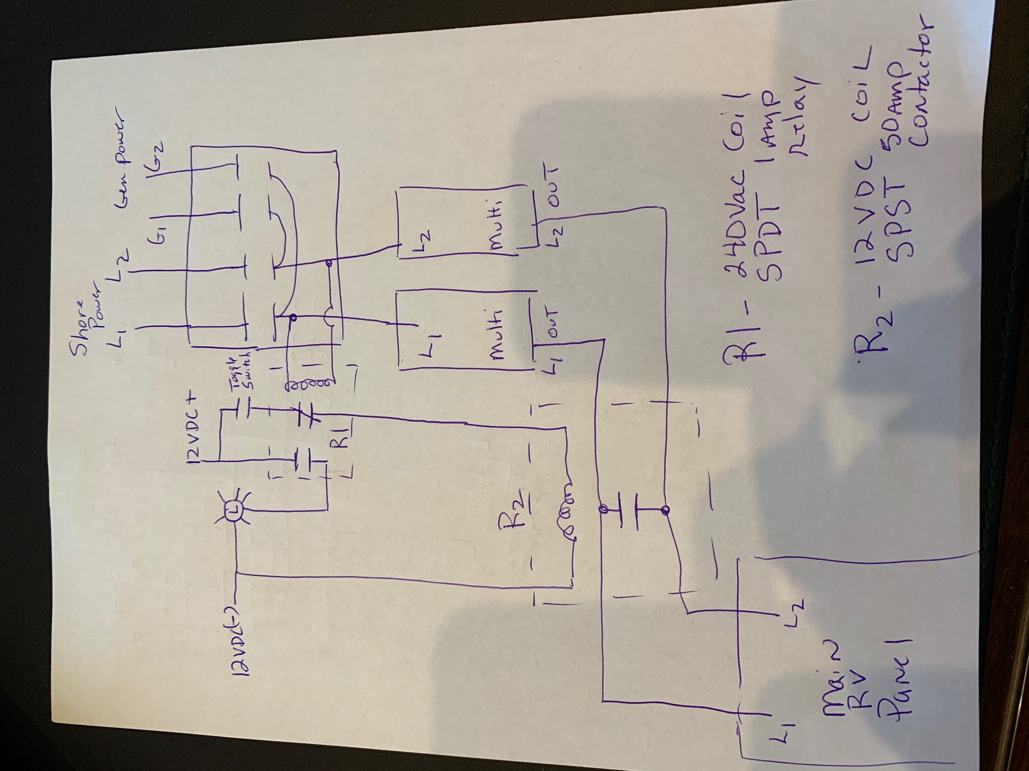
I have two Multiplus 3000 mounted up in my 50amp RV. I want to run a leg from each phase coming in to each Multiplus. That way each side of the breaker panel has its own Multiplus. Has any one done this? How would you wire the Color Controller? Just run the Cat to one and run another Cat from one to the other? Would it work that way?


The Multiplus' run fine, charge as they should and power everything just fine running a leg each. Should I just parallel them and be done with it or can this work? Any help would be appreciated.

MultiPlus Quattro Inverter ChargerCCGX Color Control
2 |3000

Up to 8 attachments (including images) can be used with a maximum of 190.8 MiB each and 286.6 MiB total.

5 Answers
Matthias Lange - DE avatar image
Matthias Lange - DE answered ·

You can (should) configure the two MultiPlus to work as split phase system.

https://www.victronenergy.com/live/ve.bus:manual_parallel_and_three_phase_systems

2 |3000

Up to 8 attachments (including images) can be used with a maximum of 190.8 MiB each and 286.6 MiB total.

john-ballman avatar image
john-ballman answered ·

Brian I am doing exactly what you are doing, and I have just started connecting my batteries. Matthias is correct as I have mine configured as split phase 240. You will need a MK3 usb to cat 5 converter, and run the VE Bus System Configurator.

1 comment
2 |3000

Up to 8 attachments (including images) can be used with a maximum of 190.8 MiB each and 286.6 MiB total.

john-ballman avatar image john-ballman commented ·

Correction 2-phase 180 degree

0 Likes 0 ·
Kevin Windrem avatar image
Kevin Windrem answered ·

The split phase setup is the correct configuration. That way, they appear as one unit to CCGX. You'd loose a lot of control if they are kept separate like inverter on/off/charge only and probably total powers.

One issue with this is when the RV is connected to single phase power as is often the case here in the US campgrounds. In this case, both legs are in phase. Theoretically, this should work with the floating phase selection but others have reported here that it does not.

2 |3000

Up to 8 attachments (including images) can be used with a maximum of 190.8 MiB each and 286.6 MiB total.

john-ballman avatar image
john-ballman answered ·

I have just confirmed that a single phase input with both multiplus programmed as floating phase does not work. Can a mk3 be used as an input on a GXCG and a cat 45 from the other on vebus?

If they are separate how will the chargers work? Does a second GXCG solve my issues?

2 |3000

Up to 8 attachments (including images) can be used with a maximum of 190.8 MiB each and 286.6 MiB total.

john-ballman avatar image
john-ballman answered ·

The purpose of this information is intended to address the fact that campgrounds in the USA may provide 50 amp 240-volt split phase or 50 amp single phase shore power, and to allow the user to easily convert a duel multiplus configuration from split-phase to parallel configuration with a flip of a switch.


There are 4 components required:

  1. R1 which is a 240vac coil, SPDT 1 amp relay. R1’s purpose is to monitor the ATS output and go active if the incoming shore or generator incoming power is 240 volts. Pole #1 will provide 12vdc+ to a light located in the RV control box. Pole #2 will disable the active state of R2.
  2. Toggle Switch is a SPST make or break toggle switch that will activate R2’s 12vdc coil if the incoming power is not 2 phases, but parallel single phase. The light is to alert the user NOT to toggle the switch in the event of 240vac and R1 is a safety precaution if the toggle switch is accidentally toggled.
  3. R2 which is a 12vdc coil, SPST 50amp vac relay/contactor. R2 provides a transfer path between the two Multiplus outputs if the incoming power is single phase parallel feed. This will also activate L2’s multiplus output.
  4. The led light is 12vdc located next to the toggle switch which is to show that the incoming voltage is 2 phase 240 volts.


With this installation and utilization of the VRM, I can quickly convert from split phase to parallel configurations in less than a minute from inside of my camper. Additionally the required neutrals for the system are not shown for simplicity’s sake, and the parallel configuration doubles the load on the neutral, I suggest that the neutral from both multipluses are run to the neutral bus bar.img-0585.jpg


img-0585.jpg (495.9 KiB)
2 |3000

Up to 8 attachments (including images) can be used with a maximum of 190.8 MiB each and 286.6 MiB total.