question

myhomebuzz avatar image
myhomebuzz asked

Your evaluation before installation

Hi Folks

Before installing my system in my motorhome, I wanted to submit to your experiences on this installation.

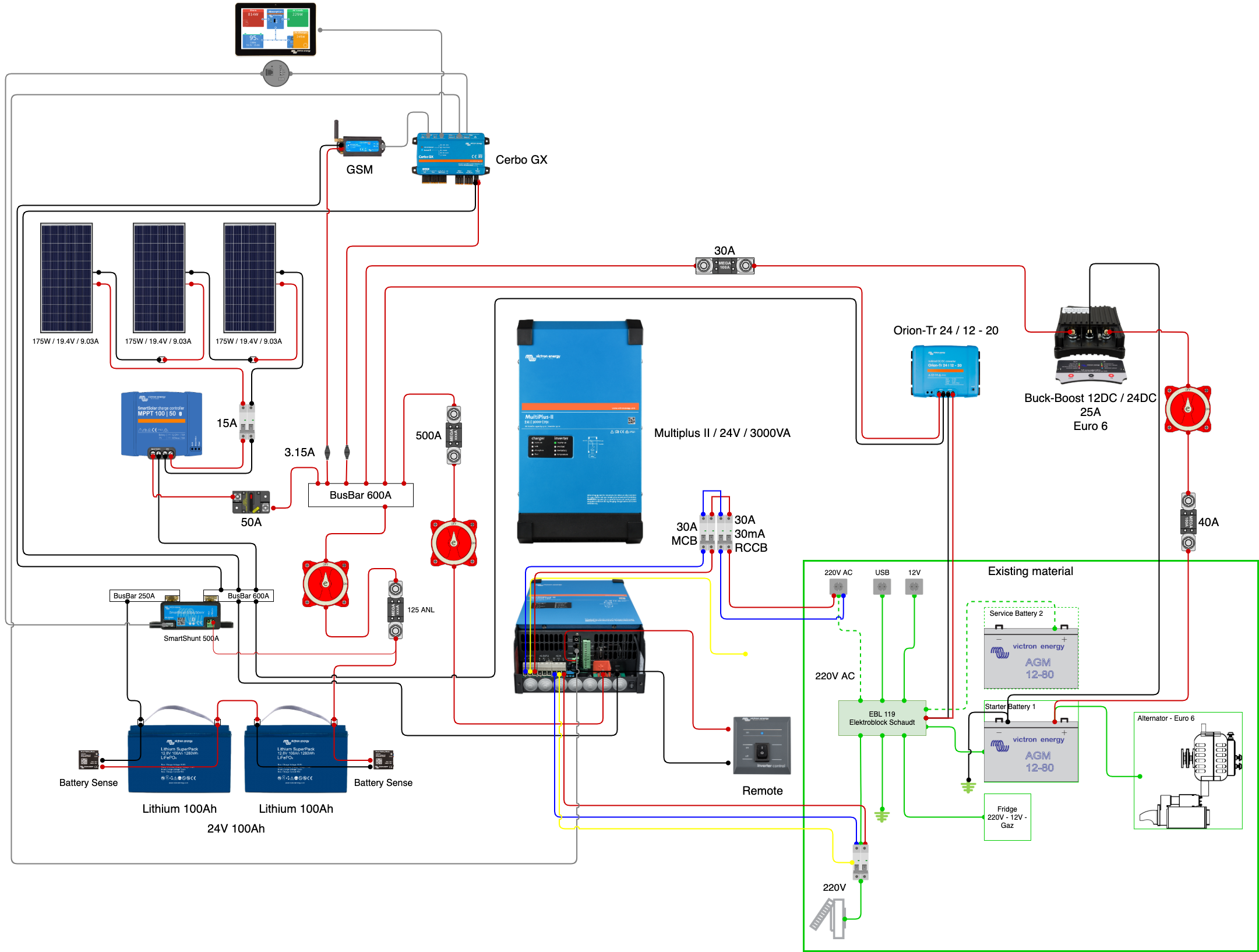
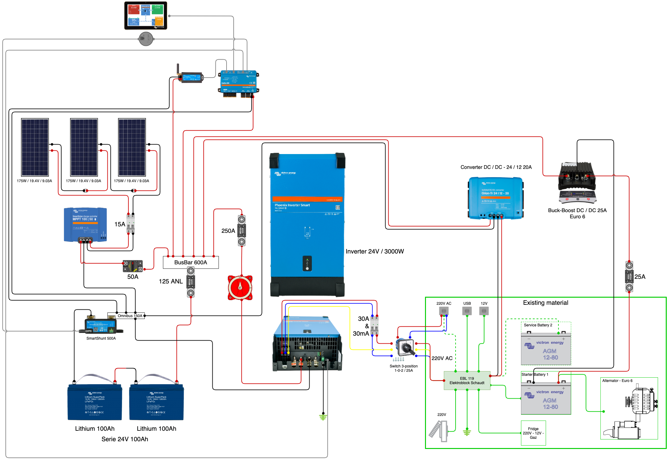
The green part is the support panel. The cables pass through the rounds to pass to the rear. This forms like a door with a hinge to facilitate assembly and to carry out subsequent additions of elements. The dimensions of all elements are exact dimensions in mm. The thin cables are in 2.5mm2 or VE.Direct or USB, the medium ones in 16mm2, the batteries in 35mm2. The battery fuses are 175 ANL. The red lines are + or Line or Phase, the black lines are - or Neutral.

No cables cross and the support panel is 80 cm x 60 cm, made of fireproof wood. Did I miss something in this assembly diagram?

I thank you in advance.


victron.png

battery chargingwiringsystem designwiring diagramsystem integration
victron.png (1.1 MiB)
2 |3000

Up to 8 attachments (including images) can be used with a maximum of 190.8 MiB each and 286.6 MiB total.

5 Answers
seb71 avatar image
seb71 answered ·

No grounding? Or you wanted to keep the drawing less cluttered?


The wires between the busbars and 12/2000 inverter should be 70mm2, with the positive wire protected by a 300A fuse.


The positive battery wires should be equal length.

The negative battery wires should be equal length. You could use a small busbar (copper bar with drilled holes) before the shunt.

If those battery wires are 35mm2, use a 125A fuse on each, not a 175a fuse on each.


Those items on the opposite/back side of the inverter are fuses (on PV wires and on battery-solar charger wire)?


Use a RCCB+MCB or an RCBO on AC out.


Did you already bought the components? If not consider a 24V system.

Also, you could skip the Cerbo GX display. And since you have a Cerbo GX, the BMV could be replaced by a SmartShunt (cheaper).

2 |3000

Up to 8 attachments (including images) can be used with a maximum of 190.8 MiB each and 286.6 MiB total.

JohnC avatar image
JohnC answered ·

Hi @MyHomeBuzz

Just general stuff..

No shore power/generator? I'd use a Multiplus instead of the Phoenix. 350W of panel as a sole supply I'd be wary of.

The Battery Protect I'd flick with a Multi. I'd use one with direct dc loads though, but you don't mention having those.

An alternator charger might be missed too, maybe a Smart DC>DC charger?

A 100/30 mppt would suffice, and be cheaper.

2 |3000

Up to 8 attachments (including images) can be used with a maximum of 190.8 MiB each and 286.6 MiB total.

myhomebuzz avatar image
myhomebuzz answered ·

@seb71 Thank you

Here some informations about your comment :

The elements on the back: indeed, I had not commented on this. These are two thermal circuit breakers of 25 A input from the PV (They will serve as a breaker for intevention / replacement / addition). the 3rd is also a 40 A thermal circuit breaker at the output of the MPPT controller.

All the elements are not in my possession, ready to be installed.

I will follow your advice and switch to 70mm2 for connection to the Inverter. This one is a 3000, not like the picture (2000).

The battery cables will all be the same length.

The Cerbo GX will allow me other connections and management from home, because my motorhome will be far from my home.

Just one more question on your advice: I replace all the cables in 70 mm2: BusBar -> BatteryProtect -> Inverter?

Thank you very much for your answer

10 comments
2 |3000

Up to 8 attachments (including images) can be used with a maximum of 190.8 MiB each and 286.6 MiB total.

seb71 avatar image seb71 commented ·
Just one more question on your advice: I replace all the cables in 70 mm2: BusBar -> BatteryProtect -> Inverter?

Yes, but if the inverter is 12V/3000 (and not 12V/2000), then maybe use 2x50mm2 (total 100mm2) wires between the busbars and inverter (and 350A-400A fuse for the double wire) and 50mm2 wires between each battery and the busbars (and 175A-200A fuses on each).

0 Likes 0 ·
myhomebuzz avatar image myhomebuzz seb71 commented ·

First of all, thank you for your answer.

I find it difficult to understand the need for 100 mm2 for 6000 W cables, as for the 70 mm2 of 4000 W mentioned above.


Calculation basis :

3000 VA converter.

Maximum peak power 6000 VA, taken into account in the calculation.

A = 6000 VA / 12 = 500


Formula: R x l2 x A / Uv = S

R (copper resistivity 0.0179) x l2 (length x 2 in m - outward and return = (2 x 1) = 2 m maximum for me) x 500 A / 0.03 (loss of ~ 3% according to Ohm law) x 12 (Volt) = 49.72 mm2 = 50 mm2 rounded, pushed to 75 mm2 (3 cables of 25 mm2) for a margin and especially a maximum terminal clamp of 25mm2 ;-)


But I'm thinking of switching to a smaller converter after having lowered my needs. A 1600 VA converter will do very well with an allowable peak of 3200 VA/W. This will also bring down the price of cabling and equipment.


Thank you for your debate and support.

0 Likes 0 ·
seb71 avatar image seb71 myhomebuzz commented ·

They don't manufacture wires in 1mm2 increments. When you are between sizes, you should go to the larger one. Ideally a single wire, but as wire cross section increases, the wire is difficult to route in small spaces. So 2 smaller wires instead of a bigger wire is a compromise. I would not go with 3 wires.


You said you already have the components. Now you wrote that you could get a smaller inverter instead. So which is it?


Edit

Also, I would aim for less than 3% voltage drop on battery-inverter wires.

0 Likes 0 ·
myhomebuzz avatar image myhomebuzz seb71 commented ·

Thank you very much seb71 for your feedback.

This is indeed a mistake. I don't speak English correctly, my translation got a bit lost. The material is awaiting purchase.

I am looking for the best solution according to the available space. And the technique that goes with it.

I have so many questions in my head that I am losing my Latin ;-)

0 Likes 0 ·
seb71 avatar image seb71 myhomebuzz commented ·

In that case, I strongly recommend to reconsider the system and switch from a 12V system to a 24V system.


Make sure that the PV array voltage is high enough for a 24V battery.


12V Lithium Superpack batteries can not be used in series, so if you go with a 24V system, you need a different battery (24V Lithium Superpack or something else).


For 12V devices (if you have any) you will have to use DC-DC converters (from 24V to 12V).


Also skip purchasing that Battery Protect.

0 Likes 0 ·
myhomebuzz avatar image myhomebuzz seb71 commented ·

OK, great, I'm moving forward thanks to your advice.


Now if I switch to 24V is it better just one 24V battery or two 12V in series?


In my country, I can buy a LiFePo4 100Ah 12V lithium battery with a built-in bms for less than $ 1000. In this case, would it be preferable that I buy 4 batteries and put the bank of 4 12V batteries in series and parallel = 24V 200Ah or two banks in series of 24V 100Ah?


All that complicated, right?

0 Likes 0 ·
seb71 avatar image seb71 myhomebuzz commented ·
Now if I switch to 24V is it better just one 24V battery or two 12V in series?

Better get a 24V (25.6V nominal) battery.


In my country, I can buy a LiFePo4 100Ah 12V lithium battery with a built-in bms for less than $ 1000. In this case, would it be preferable that I buy 4 batteries and put the bank of 4 12V batteries in series and parallel = 24V 200Ah or two banks in series of 24V 100Ah?

In both cases, from 4 12V 100Ah batteries you will have 24V 200Ah.


First make sure that the BMS can work if you connect more batteries in series/parallel.


If you can wire individual 3.2V LiFePO4 cells, then you can put groups of 2 cells (or more) in parallel and then wire those in series (8 groups in series for 24V nominal).


But if you have 12V batteries (with 4 cells in series each), wire two batteries in series and the other two batteries in another series and then put those two battery strings in parallel. As I said, assuming that the 12V battery BMS can work in this way (the BMS-es must coordinate in some way, at least for the two batteries in series).

0 Likes 0 ·
myhomebuzz avatar image myhomebuzz seb71 commented ·

According to the manufacturer's data, a maximum of 4 12V batteries can be put in parallel or in series. Perfect, this solves the Lithium battery part.


According to JohnC's post above, he suggests a Multiplus rather than a Phoenix Single Converter. The Multiplus is indeed also a converter and a charger. Do you have any knowledge with this Multiplus to discuss it here or do I have to open another post?


Because I have another 12V 95Ah AGM battery in the cabin of the motorhome (original) that I would also like to couple to the Lithium bench. I didn't mention this in this post, but I can easily reproduce and modify the design for better understanding.


Your comments are greatly appreciated.

0 Likes 0 ·
seb71 avatar image seb71 myhomebuzz commented ·
According to the manufacturer's data, a maximum of 4 12V batteries can be put in parallel or in series. Perfect, this solves the Lithium battery part.

Check if also 2s2p is also allowed.


According to JohnC's post above, he suggests a Multiplus rather than a Phoenix Single Converter. The Multiplus is indeed also a converter and a charger.

Yes, a Multiplus (or Multiplus II) is a better choice than a Phoenix inverter, because it can also charge the batteries or power your loads from grid (when grid is available).


Because I have another 12V 95Ah AGM battery in the cabin of the motorhome (original) that I would also like to couple to the Lithium bench.

Not sure what you want to do, but in principle don't mix lead-acid batteries and LiFePO4 batteries.


You might want to contact someone who designs such RV/motorhome systems.

0 Likes 0 ·
myhomebuzz avatar image myhomebuzz seb71 commented ·

@seb71


Thank you very much for your support.


I'll fix my system, put the missing elements in the design and come back with it.


Following the next episode ;-)

0 Likes 0 ·
myhomebuzz avatar image
myhomebuzz answered ·

Hi @JohnC

Indeed, I did not do all the electrical diagram of the motorhome. An EBL is existing and I would connect to it.

There is also a 220V power supply from the outside. I have not implemented this in my diagram. I also provided the charger from the vehicle's alternator. This is another design.

The purpose of this diagram is to make everything fit on my hinged support panel.

I will improve and integrate all the elements in my other design.

The MPPT 150/35 will be used, depending on use, to couple with another 175 W panel.

Thank you very much for your support.

2 |3000

Up to 8 attachments (including images) can be used with a maximum of 190.8 MiB each and 286.6 MiB total.

myhomebuzz avatar image
myhomebuzz answered ·

Hi Folks

I'm back !

I made the changes to the first design including the existing material.

The existing equipment, framed in green at the bottom right, is physically located inside the vehicle. The green lines leave from EBL119. EBL119 is an original electric unit and integrated into the vehicle. It is used for the distribution of the 12V / 220V current and for the management of a single AGM cabin service battery as well as a starter battery. EBL119 accepts only 12V / 220V and Yes, I switched to 24V instead of 12V thanks to your comments. I have not yet determined the cross section of the cables, but this also depends on the lengths to be seen on site.

My objective :

- Remove the elements framed by a dashed green line as well as the green dashed lines: service battery and direct 220V line to the distribution to the outlets.

- Leave the EBL119 in place but by installing a 3-position switch for the distribution of 220V in the 5 existing outlets in the vehicle: 0- no current input, 1- 220V power supply by the converter, 2- power supply 220V from the external connection of the vehicle.

- Recharging of the Lithium batteries with a Buck-Boost due to a Euro-6 alternator.

Still to be resolved:

- Recharging of the 24V Lithium battery bank by the external 220V power supply of the EBL119 or directly by a separate power supply to a charger? I don't know the best yet. Can be with a converter / charger instead of the only converter.

Does this speak to you and am I on the right track?

Thanks a lot for your fabulous comments about this project.

victron-12v-rev3.png


2 |3000

Up to 8 attachments (including images) can be used with a maximum of 190.8 MiB each and 286.6 MiB total.

Related Resources

Additional resources still need to be added for this topic

Victron Wiring Unlimited Book