question

udo229 avatar image
udo229 asked

VE.Bus Specification

I've got a three-phase ESS System with 3 Multiplus-II and an Octo GX as Controller. It works for two years, sometimes I had to reset the system, but what's perfect.

Last Month there was an dramatic increase of different VE.Bus Errors.

One Multi with the Octo works well, all Three Multis on the Bus leads to VE.Bus Errors after few Minutes.

I've Oszillographed Pin 4 and 5 of the VE.Bus of each Multi without any Cables attached an found big differences.

What are the Specs of the VE.Bus. I'm working since 30 Years with transmission system and I've got a Degree in Electronics, but my Dealer want's me to send him my whole equipment.

Anyone here to interprete my measurements?


vebus-wechselrichter-phase-1allein.jpg

vebus-wechselrichter-phase-2allein.jpg

vebus-wechselrichter-phase-3-allein.jpg


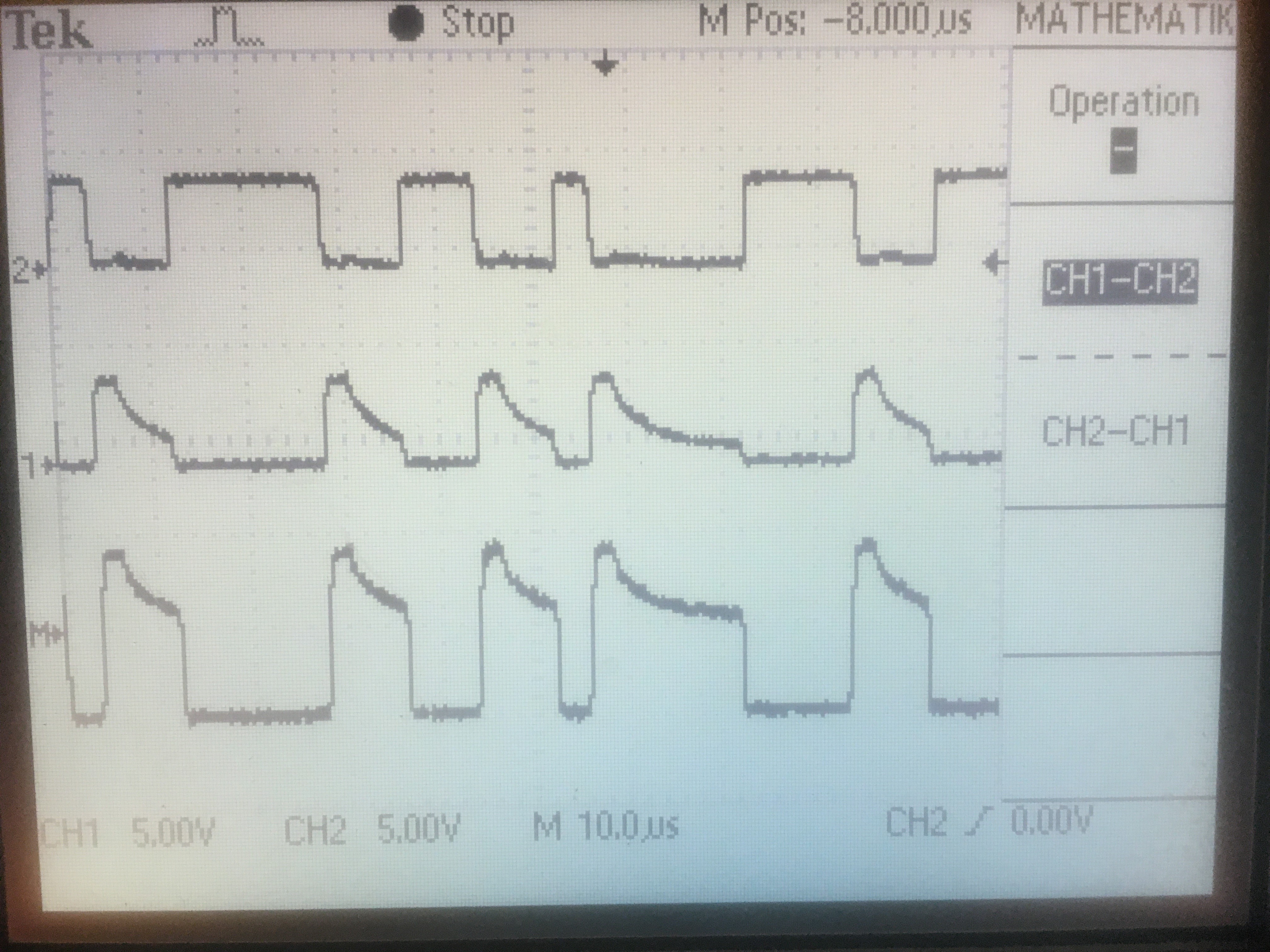
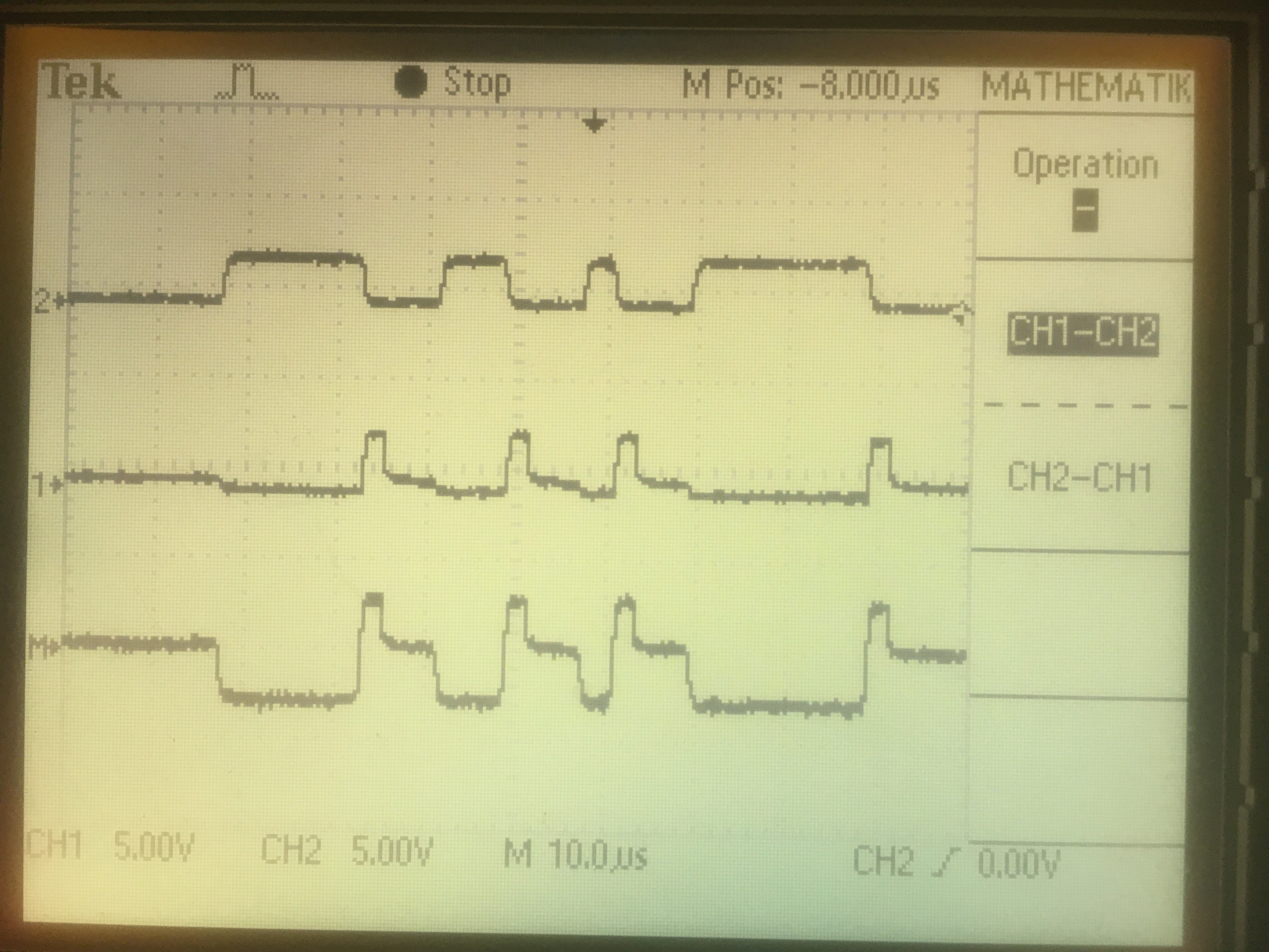
perfect Rectangles look different, but especially the Signal of the third Multi is only half of the other two above.

After switching off AC and DC I measured the resitance between Pin 4 and 3 (ground) and Oin 5 and 3.

It was always 14 to 15 kiloohms, only on the third Multi with the weak signal it was pin 4 to 3 only 76 Ohms (no kilo!)

I think it is enough to give this Multi closer observation, only attaching it to the Octo works, the Errors occure lnly with more actice Devices on the Bus...

VE.Bus
2 |3000

Up to 8 attachments (including images) can be used with a maximum of 190.8 MiB each and 286.6 MiB total.

2 Answers
jacola avatar image
jacola answered ·

Hi Udo, i have also about 43 years of serial comms on my back .. :)
As far as i know the VE.Bus stuff uses 485 .. and if you 'read' the signals with that idea and a typcial diffential receiver the bus is clean.

A usual 485 receiver (75176) will have a few kohms input impedance, but 76 ohms sound that there might be a line end termination resistor installed (which would make sense, the speed on your screenshots points to 250kbps .. there you would terminate. Maybe the devices have a programmable resistor, but maybe the receiver is just fried ..
Would help to take a pic at the schematic and what receiver chip is used.
Do you have a Mk3 ? I have some simple lua code to read and dump ve.bus messages, not that i understand everything, but at least one can see cerbo/venus comms with the phase master as well as messages between the devices and i am able to get setpoints, actual values of all devices etc etc. Could help to run this to see if checksum errors happen, and if, if they are happening just with one device.


Johannes


2 |3000

Up to 8 attachments (including images) can be used with a maximum of 190.8 MiB each and 286.6 MiB total.

udo229 avatar image
udo229 answered ·

The 76 Ohms occur at only ONE of the three Multis and only on one Pin. All other five Pins (the four on the other two Multis and the second pin of the suspicious Multi) show the 14 kOhms.

Also there is no Termination or something else plugged on the VE.Bus connectors. I haven't found a "Termination on"switch or something like that in the specification or software.

So I can't explain the measured resistance nor the low Amplitude on the third Multis. I haven't found any specification of the Amplitude or Signalforms of the VE.Bus yet.

It's frustrating, after some hours the Multis stop working after an VE.Bus Error occurs. Earlier this month there were different Error, now it's "Incompatible Firmware", which is ridicoulous, because for some hours its working and I had crosschecked the firmware of all multis, Octo and mppts, it's always the newest one.


2 |3000

Up to 8 attachments (including images) can be used with a maximum of 190.8 MiB each and 286.6 MiB total.

Related Resources