question

Louis van der Walt avatar image
Louis van der Walt asked

Victron VenusOS driver for serial battery BMS - JBD / Daly / JKBMS / Renogy / ECS , etc.

Hi

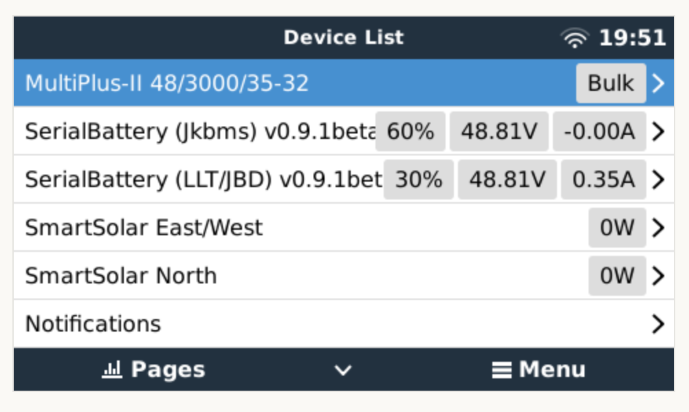
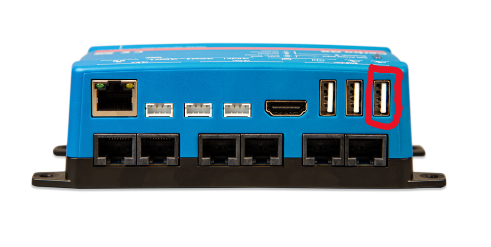
I have created a VenusOS driver that can talk to BMS/Batteries that has serial communications (instead of the normal CANbus). RS485/RS232/TTL/UART and Venus 2.80+ have been tested.

Currently it works with

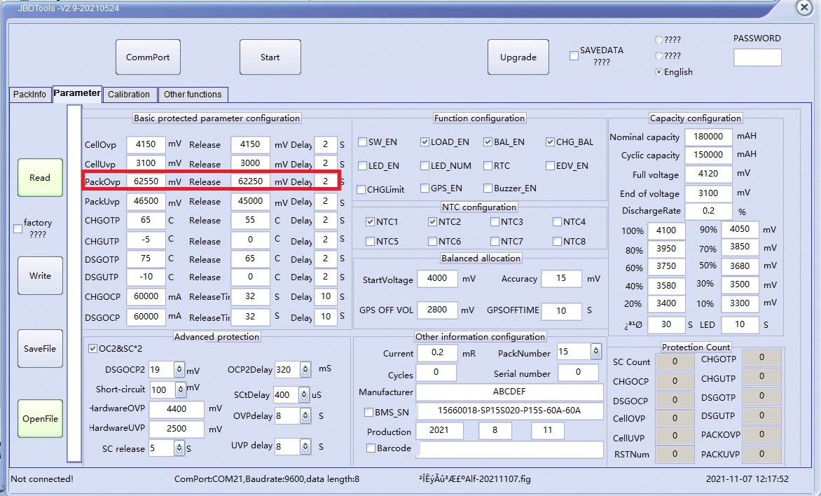
  • JBD BMS (LLT Power / Overkill Solar)
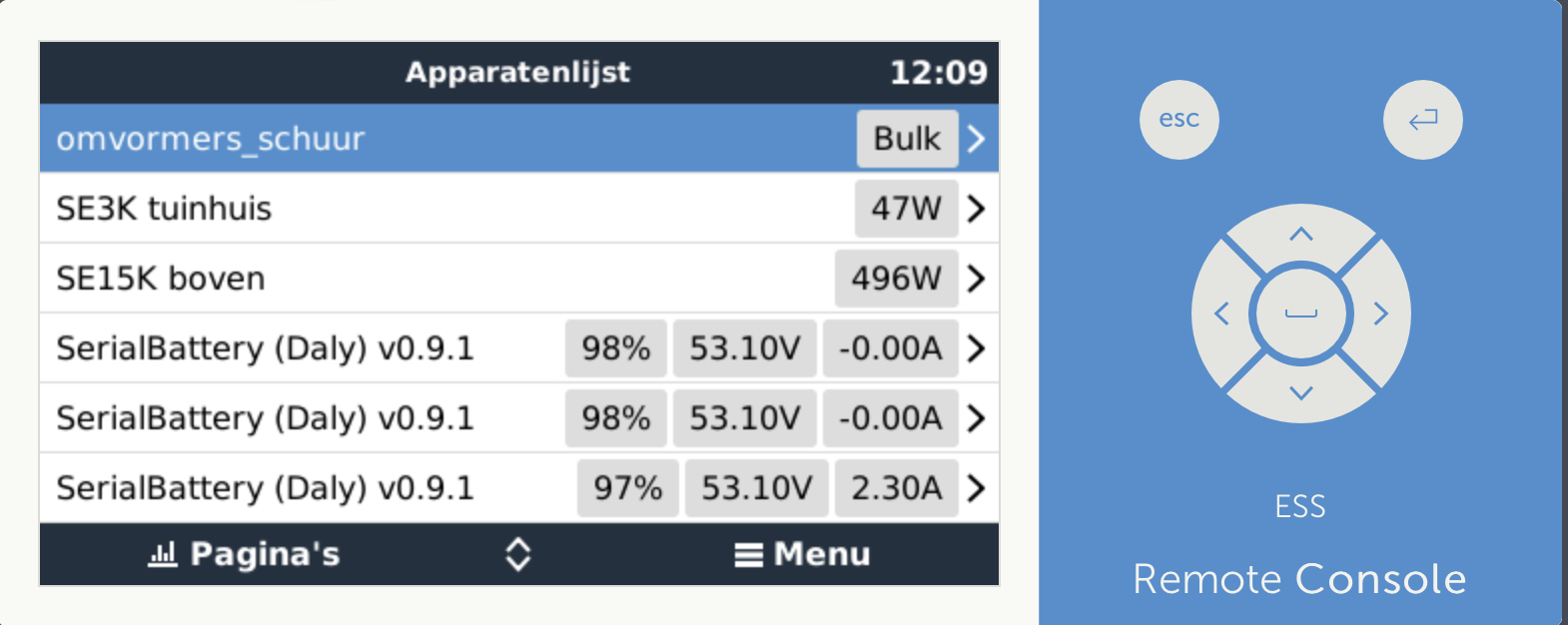
  • Daly BMS (Daly Smart BMS / Daly Sinowealth based BMS)
  • ANT BMS
  • MNB spi BMS - disabled by default as it requires extra libraries installed to work. Contact @Mike Dorsett for information
  • JKBMS / Heltec
  • Renogy
  • Tian Power BMS (Revov battery / LifePower)
  • ECS (GreenMeter)


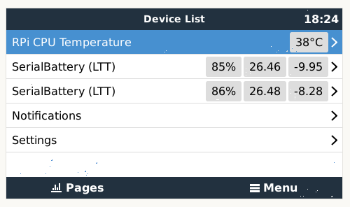
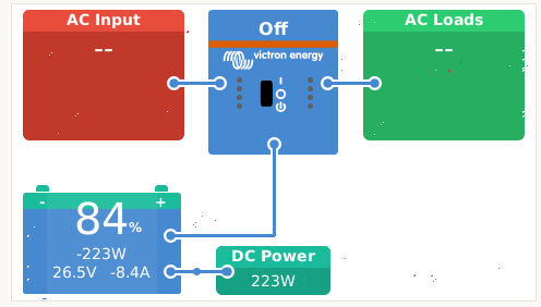
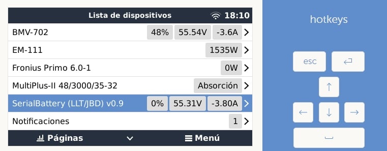
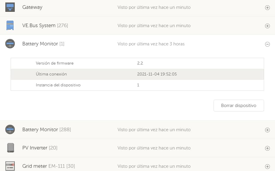
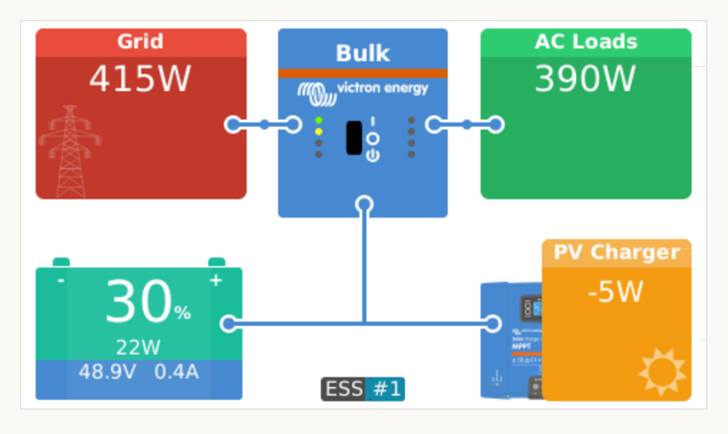
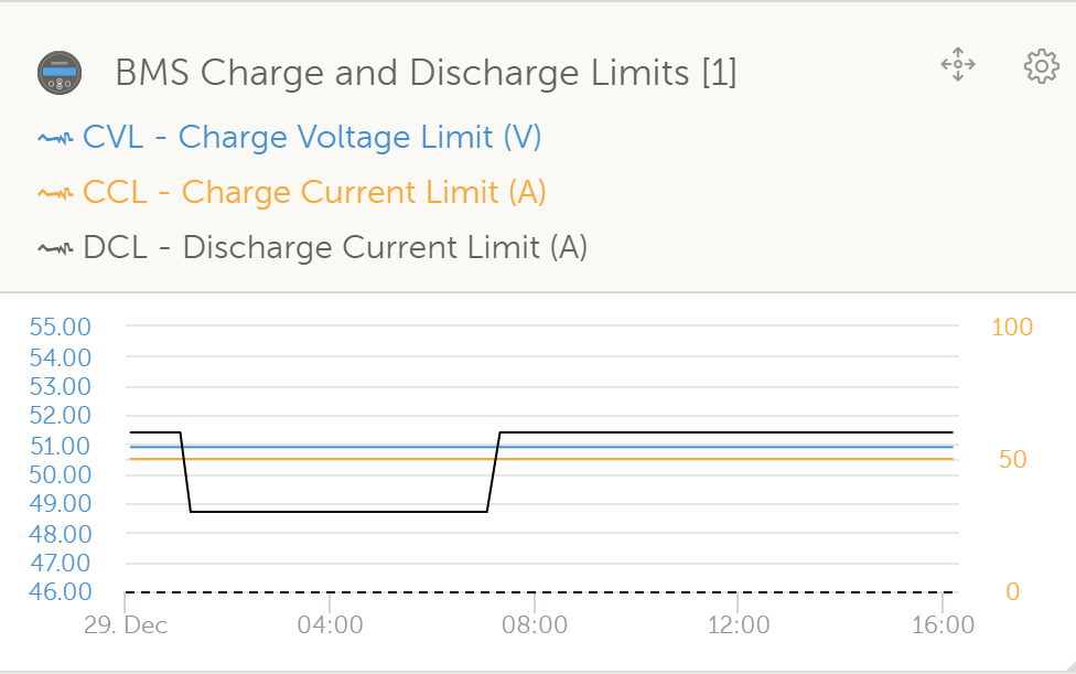
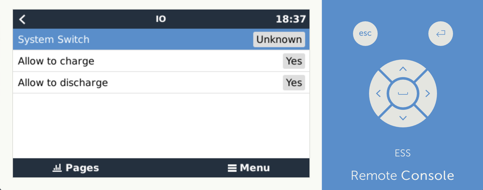
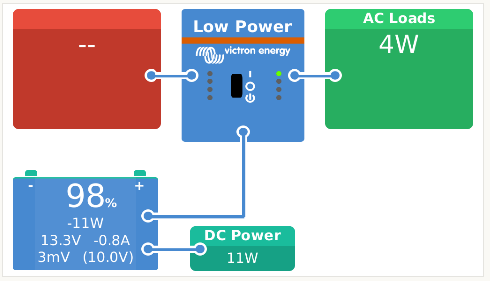
The driver will act as Battery Monitor inside VenusOS which will also publish the battery to your VRM.
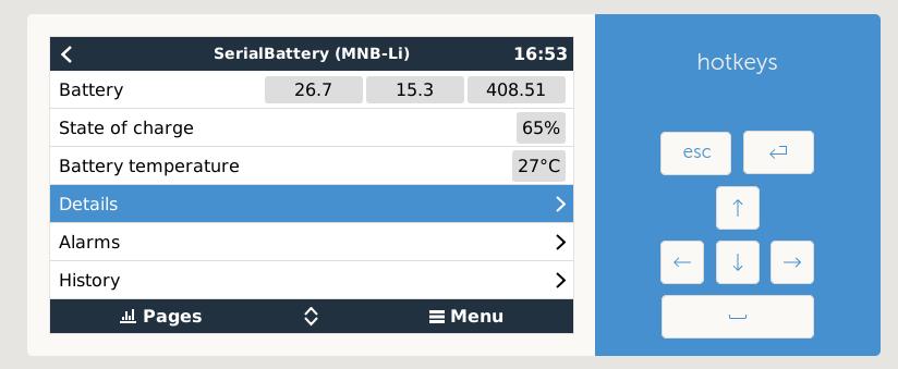
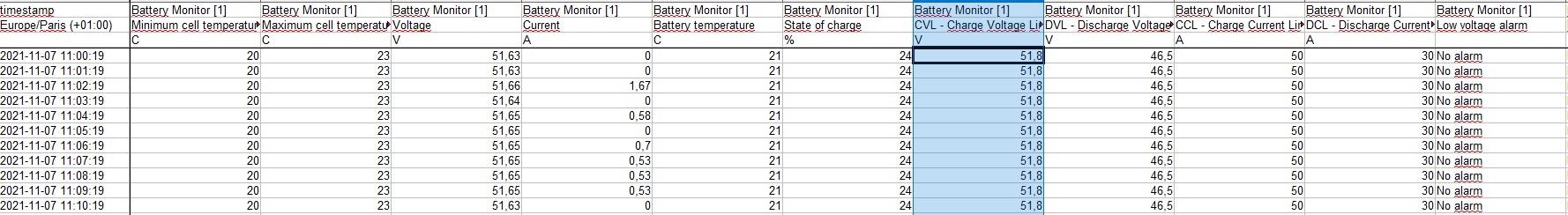
The following values are included:

  • State Of Charge
  • Voltage
  • Current
  • Power
  • Can handle batteries with from 3 - 32 cells
  • battery temperature
  • min/max cell voltages
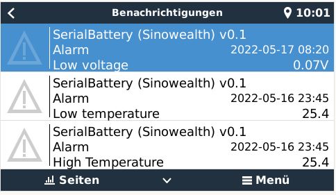
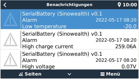
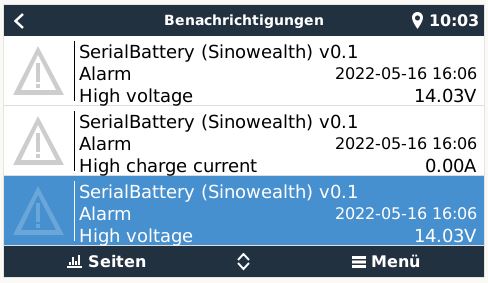
  • raise alarms from the BMS
  • available capacity
  • history of charge cycles

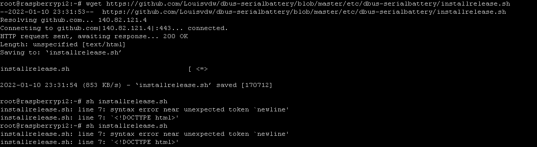
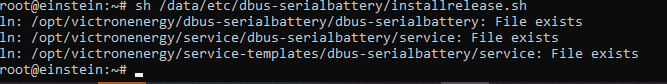
The current release is on GitHub if you want to check it out.
You can up-vote for your BMS to be added to the driver in the here on github.
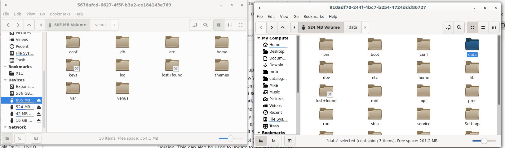
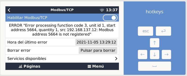
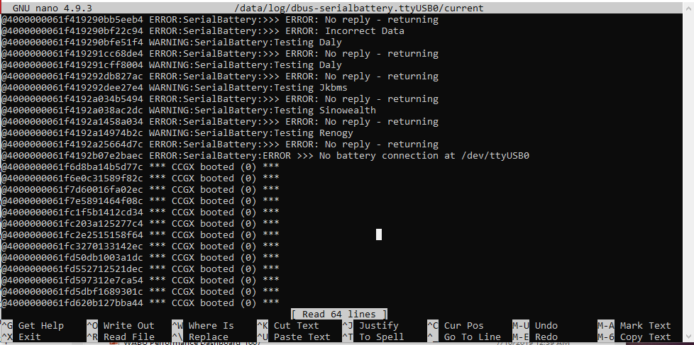
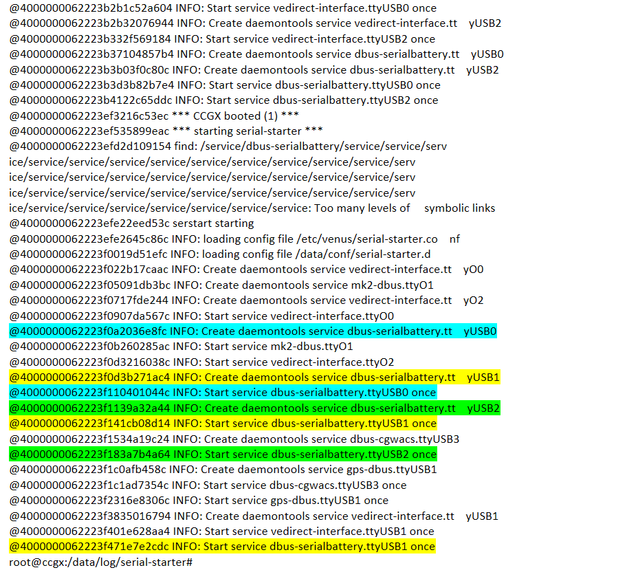
Documentation with install instructions and troubleshoot is available here


BMV Battery MonitorVenus OSBMSrs485
2 |3000

Up to 8 attachments (including images) can be used with a maximum of 190.8 MiB each and 286.6 MiB total.

126 Answers
Elimac avatar image
Elimac answered ·

Hello!

Very nice work! I did not test it (yet) - I'm using individual cells with JBD BMS, but I have one question:

- I am using in fact 2 battery banks in parallel, one with its own BMS (100A/24V) from LTT Power. If one bank is removed, the remaing bank can handle the typical loads and charge current.

Can your application deal with parallel banks, each with its own BMS?

4 comments
2 |3000

Up to 8 attachments (including images) can be used with a maximum of 190.8 MiB each and 286.6 MiB total.

Louis van der Walt avatar image Louis van der Walt commented ·

At the moment it can only handle 1 battery bank, but I do plan a second battery bank myself so this will be something I looks at in the future.

0 Likes 0 ·
Elimac avatar image Elimac Louis van der Walt commented ·

That would be incredible. Let me know if you need help testing. I'm using currently 2 banks, and have another 2 standing by for next Winter. I will have 4 banks @24V, with plans to convert later to 2x @48V if I can get new inverters. I only have JBD at the moment, several different models.

0 Likes 0 ·
blankc avatar image blankc Louis van der Walt commented ·
I second this request. I am currently using your driver with a 12v Daly 250amp BMS UART and it works great; but I have several more cells that I would like to add to my system using a second BMS. Is there any reason that it won't work as is before I go buy another BMS?
0 Likes 0 ·
Louis van der Walt avatar image Louis van der Walt blankc commented ·
There are a few things that I need to test if they will work as planned, but in theory you should be able to have multiple battery banks running.
0 Likes 0 ·
mvader (Victron Energy) avatar image
mvader (Victron Energy) answered ·

Super cool @Louis van der Walt

2 |3000

Up to 8 attachments (including images) can be used with a maximum of 190.8 MiB each and 286.6 MiB total.

federico993 avatar image
federico993 answered ·

Very interesting! Will you add the REC BMS at the list?

The instructions for the serial connection are listed in the manual.

1 comment
2 |3000

Up to 8 attachments (including images) can be used with a maximum of 190.8 MiB each and 286.6 MiB total.

Louis van der Walt avatar image Louis van der Walt commented ·

@Federico993 I looked at the REC BMS and it should be able to be added.

0 Likes 0 ·
Elimac avatar image
Elimac answered ·

This weekend I gave it a try.

I want to thank Louis for this work - it really fits with my installation :). I left my VenusGX unchanged, and for the time being this will continue to be the main unit that controls the whole installation and I used a dedicated Raspberry to experiment with this thread software.

I have LA OpZS in parallel with 2x LiFEPO4 packs, the latter do all the work - Lead Acid is only discharged rarely, like a Backup for extended periods without sun. I had a small PC running windows with LLT application to monitor and change the BMS parameters. Main function was to monitor remotely cell balance in both packs in absorption. With this VenusOS addon, I can at least monitor both packs at the very low power cost of the raspberry instead of x86 PC.

Here's the main menu of raspberry as of today:

1612722993091.png

I tried with both packs, even though was stated not to be supported, but in fact I seem to be able to monitor both packs, which was what interested me most!

And front page:

- Here we can see that the Battery data is only referreing to one of the packs, and not the SUM/ association of all packs. It's ok for me at the moment :)

EDIT: Both packs have same VRM id. This is a pitty, the current major limitation - only one BMS can be monitored in VRM.

1612723045836.png


I'm using the Pi as an AUXiliary VenusOS, just to monitor Lithium BMSs. I still have Main Venus OS in another IP, with global data available and it is the one controlling the MPPTs for the moment.

Congratulations to Louis and keep up the excellent work! It would be absolutely delightful if this software could also change BMS parameters like the original LLT windows application does, but I don't want to ask too much :)


PS: Since I was at it, I also installed the Temperature monitor (thanks LHardwick): https://github.com/LHardwick-git/Victron-Service


1612722993091.png (20.9 KiB)
1612723045836.png (17.8 KiB)
6 comments
2 |3000

Up to 8 attachments (including images) can be used with a maximum of 190.8 MiB each and 286.6 MiB total.

Elimac avatar image Elimac commented ·

Just a note @ Louis van der Walt: I had some issues with the folder's location. I think there is some confusion in the instructions, as there is no

  • /data/etc/dbus-serialbattery/dbus-serialbattery.py
  • /data/etc/dbus-serialbattery/service/log/run
  • /data/etc/dbus-serialbattery/service/run
unless I copy them too. Or, there is an "etc" missing somewhere.

I assumed you want us to copy what is inside "etc" to the main "etc" on Pi, and I did managed to make it work... but I got a little confused.


0 Likes 0 ·
Louis van der Walt avatar image Louis van der Walt Elimac commented ·

@elimac, yes the etc has to go to etc on the venus/pi. The folder structure is so that the auto installer will place the files in the correct locations and it extracts the venus-data.tar.gz to the /data/ folder. I'll make the instructions for the manual installation a bit clearer. Thanks for the suggestion.

0 Likes 0 ·
alekspoker2 avatar image alekspoker2 commented ·
Hi Louis,

Will this work with the JBD BMS UART interface (non isolated)? That's what comes by default with the BMS I ordered. I do have an uart to USB cable that i would use. It also has the Bluetooth interface, but i want the Bluetooth module to stay connected so i can check the battery separately with the JBD app.

0 Likes 0 ·
Louis van der Walt avatar image Louis van der Walt alekspoker2 commented ·

Yes the JBD BMS UART is the easiest way to get it to work. It will be fine.

1 Like 1 ·
izeman avatar image izeman alekspoker2 commented ·
@Alekspoker2 How do you attache BT module and UART at the same time? My xiaoxing BMS only has ONE communication port and I can connect one or the other. Would be really helpful to have both at the same time. Thanks
0 Likes 0 ·
Louis van der Walt avatar image Louis van der Walt izeman commented ·
When you order the BMS from the factory you can request extra TTY UART port, or on most models an RS485 port along with the TTY that the bluetooth module use. By default if it does not state it you will only have the one TTY UART port for the bluetooth.
0 Likes 0 ·
Jaco Reinecke avatar image
Jaco Reinecke answered ·

This is THE best software since sliced toast ... toasted in a toaster powered by a Victron setup.

Been using it for months now, Louis is absolutely committed, and it WORKS, on my Venus and Rpi Venus.

2 |3000

Up to 8 attachments (including images) can be used with a maximum of 190.8 MiB each and 286.6 MiB total.

gyrex avatar image
gyrex answered ·

Hi Louis, thanks for your incredible work on this project! I was wondering if you've made any progress on Daly BMS?

2 comments
2 |3000

Up to 8 attachments (including images) can be used with a maximum of 190.8 MiB each and 286.6 MiB total.

Louis van der Walt avatar image Louis van der Walt commented ·

Hi @gyrex. I'm currently busy with the Daly integration. Just need to change some pieces of the existing code so that it will work better for different BMS types. I see you have subscribed to the issue for Daly integration, so you will be notified when there is something to test

0 Likes 0 ·
pau1phi11ips avatar image pau1phi11ips commented ·
Daly is working now by the way.
0 Likes 0 ·
justin-schoen avatar image
justin-schoen answered ·

Is it possible to use this on the BMS-CAN ports on a cerbo gx

1 comment
2 |3000

Up to 8 attachments (including images) can be used with a maximum of 190.8 MiB each and 286.6 MiB total.

Louis van der Walt avatar image Louis van der Walt commented ·
No, BMS-CAN would not work. It's not working through the GX serial interface that I am using.
0 Likes 0 ·
ve7mmg avatar image
ve7mmg answered ·

What you are doing is awesome. can I use it in conjunction with a smart shunt?

Thanks,

Mike

1 comment
2 |3000

Up to 8 attachments (including images) can be used with a maximum of 190.8 MiB each and 286.6 MiB total.

Louis van der Walt avatar image Louis van der Walt commented ·
Yes you can use a smart shunt with this. In the Remote Console you can choose which Battery Monitor must be used for the system. The other will just be reported.


By default the BMS will be used as the battery monitor. If you don't use the BMS and your cells are imbalanced, the BMS SOC will be adjusted to compensate, while any other shunt would not know about the cell imbalance. It is recommended to use the BMS data as the battery monitor.
0 Likes 0 ·
Mike Dorsett avatar image
Mike Dorsett answered ·

This looks very interesting. I'm looking into integrating my BMS software with the Venus OS. My BMS software runs on a Raspberry pi - which plugs into the BMS PCB to communicate with the SPI port, and other I/O for driving relays (Gen start, load stop, charge stop). Given you're using Modbus RTU, I'm using Modbus TCP/IP, what would be needed to interface with the Venus software using modbus at localhost? i.e. the BMS software running under the Venus OS and communicating directly?

5 comments
2 |3000

Up to 8 attachments (including images) can be used with a maximum of 190.8 MiB each and 286.6 MiB total.

Louis van der Walt avatar image Louis van der Walt commented ·

There are 3 parts to my driver. A dbus interface, a battery interface, and the serial-starter setup.

You should be able to use most of your current code that you already have working to interface with the battery,

And the dbus interface the driver will do for you if you populate the battery object,

But because you are using Modbus TCP/IP the serial-starter will not know about the TCP/IP connection or start the driver for that interface to try and link to the battery.
If you can get the SPI port connection to be polled by the serial-starter service, that might work. Or you would have to make a hardware interface to one of the UARTs that is polled.

0 Likes 0 ·
Mike Dorsett avatar image Mike Dorsett Louis van der Walt commented ·

Hi @Louis van der Walt Thanks. I've now had a look through your code, and see the three parts. I'm trying to get your code running under Venus OS 2.66 and having some problems with the directory structure - this seems to be different from the instructions on Github, and the auto installer's don't work for me.

This is not helped by someone leaving the dir command out of the Venus bash, making navigation difficult. The Venus python is 2.7

I'm planing to use my code to populate the battery object and your dbus interface to connect to Victron's api. Currently trying to test with a fixed battery object. rc.local is normally under the /etc directory - Iv'e pt a copy there but it doesn't seem to be running on boot.

screenshot-from-2021-06-28-13-26-56.jpg

going to spend some time today trying to debug this, any pointers appreciated.

0 Likes 0 ·
Mike Dorsett avatar image Mike Dorsett Mike Dorsett commented ·
running the link command that is in rc.local by hand, I get Invalid cross-device link?
0 Likes 0 ·
Mike Dorsett avatar image Mike Dorsett Mike Dorsett commented ·
pls ignore this I missed the -s out of the command!!
0 Likes 0 ·
Louis van der Walt avatar image Louis van der Walt Mike Dorsett commented ·

Hi Mike

In the latest code you will see there is a file battery_template.py. Make a copy of that for your battery and make all the changes in it for connecting to your battery. You need to populate at least the SOC, Voltage and Current for the battery object. Then edit dbus-battery.py and also add your battery import (line 16/17) and batterytype (line 36-39) so that it is called.

If you need help open an ticket for your battery in GitHub

0 Likes 0 ·
Mike Dorsett avatar image
Mike Dorsett answered ·

@Louis van der Walt

Fiinally figured things out. Venus puts an additional /data in front of everything in the command console!. This lead to files in the wrong place. I've now got a fake (static) battery operating:

screenshot-from-2021-06-29-16-53-21.jpg

I can now figure out how to integrate this with the real BMS Software.


2 |3000

Up to 8 attachments (including images) can be used with a maximum of 190.8 MiB each and 286.6 MiB total.

nebulight avatar image
nebulight answered ·

@Louis van der Walt Great project!! Any possibility of getting the Electrodacus SBMS0 on the list? Maybe a collaboration with this guy:

https://community.victronenergy.com/questions/92229/electrodacus-sbms0-integration-with-ccgx-to-contro.html?childToView=92932#answer-92932

5 comments
2 |3000

Up to 8 attachments (including images) can be used with a maximum of 190.8 MiB each and 286.6 MiB total.

Louis van der Walt avatar image Louis van der Walt commented ·
Yes it should be very possible to integrate. That BMS has a RS232 serial interface and all the required data. Let's see what @mija wants to do.
0 Likes 0 ·
nebulight avatar image nebulight Louis van der Walt commented ·
Not sure where you are located, but if you are in the US I wouldn't mind sending you my SBMS0 if you need it for dev and testing and you can just send it back when you are done.
0 Likes 0 ·
Louis van der Walt avatar image Louis van der Walt nebulight commented ·

@nebulight that would make it much easier, but I am located in sunny South Africa.

0 Likes 0 ·
nebulight avatar image nebulight Louis van der Walt commented ·
Well I was trying to avoid large shipping costs, but if it comes down to you needing one, I wouldn't mind covering the costs as I think the SBMS0 is one of the best units for the money and if you can get it to work with the Venus OS as a managed battery, that would be great.
0 Likes 0 ·
sailor77 avatar image sailor77 nebulight commented ·
Hi! Is there a solution now for the SBMS0?
0 Likes 0 ·
spidgrou avatar image
spidgrou answered ·

WOW
@Louis van der Walt Super nice project.
I'm looking forward to test it.
I've alredy received my JBD bms, just waiting the cells.
great job, so far.

Thanks

2 |3000

Up to 8 attachments (including images) can be used with a maximum of 190.8 MiB each and 286.6 MiB total.

Louis van der Walt avatar image
Louis van der Walt answered ·

There is a new version v0.8 that include Venus OS v2.80 compatibility changes for the driver.

To upgrade a V2.72 / V2.73 device you will need to update the battery driver first, then update the Venus firmware to 2.80 and the battery will still be there on V2.80.

(You can still upgrade the driver after the firmware, but then the battery will not offline until the new driver is installed and device rebooted)


2 |3000

Up to 8 attachments (including images) can be used with a maximum of 190.8 MiB each and 286.6 MiB total.

alekspoker2 avatar image
alekspoker2 answered ·

Hi Louis, jbd has a new BMS that is 200amp 7s to 20s and it can come with CANBUS. I have one of those with CANBUS in my possession. I also have some documentation on the canbus protocol and identifiers it is using. Would you be interested in trying to make this BMS work with Victron GX devices so BMS data can be sent to GX over CANBUS?

1 comment
2 |3000

Up to 8 attachments (including images) can be used with a maximum of 190.8 MiB each and 286.6 MiB total.

Louis van der Walt avatar image Louis van der Walt commented ·
Hi @Alekspoker2

At the moment I am focusing on the ModBus RTU based implementations for BMS/batteries and there are too many outstanding items on the todo list to pivot that direction now. That might change, but for now I can't look at CANBUS as well.
PS. that model should have the bluetooth adapter and the side or inside the case, which you can unplug and connect with a TTY to USB converter to connect it and link up with the driver.

0 Likes 0 ·
Elimac avatar image
Elimac answered ·

This week end I have upgraded to version 0.9. I'm running this driver in a Raspberry Pi 3B, just for monitoring pursposes of 2x Lithium banks using each one JBD BMS, connected by USB to the Pi. I was excited to find that after the upgrade the VRM instance of the two banks was different and thus I could record both banks history in VRM Portal. Which I did - VRM instance 2 and 3. Nice!

But after one reboot, both Battery Monitors assumed the same VRM id (1), same as before. So, I'm curious. Was anything been changed to enable more than one bank recording in VRM Portal? If not, how could I briefly had this (wanted) behavihour? I'm trying to replicate and can't... now they have always same ID after reboot.


1 comment
2 |3000

Up to 8 attachments (including images) can be used with a maximum of 190.8 MiB each and 286.6 MiB total.

Louis van der Walt avatar image Louis van der Walt commented ·
I did do some work with the device instances which is the first stepping block needed to use multiple banks. That work is not finished yet which is why it showed you the 2 banks only briefly.
0 Likes 0 ·
liam-tuvey avatar image
liam-tuvey answered ·

Hi @Louis van der Walt thanks so much for your work on this.

I'm trying to understand the best way to connect / what cables I need.

I have a JBD 8s BMS with a Bluetooth adaptor connected to a 4 pin serial port. I also have a uart to usb adapter that came with the with the BMS that replaces the Bluetooth adapter. I'm connecting to a cerbo Gx.

Can I use a ve.direct cable connected to the serial port on the BMS instead, or do I need to use the USB interface?

What's the preferred way of connecting?

Many thanks

7 comments
2 |3000

Up to 8 attachments (including images) can be used with a maximum of 190.8 MiB each and 286.6 MiB total.

pau1phi11ips avatar image pau1phi11ips commented ·
You'll need to use the UART to USB connection I think. That's what I had to do with the Daly. Means you can't use the Bluetooth at the same time but I prefer to have the data in Venus/VRM over the Bluetooth connectivity.
0 Likes 0 ·
liam-tuvey avatar image liam-tuvey pau1phi11ips commented ·
Thanks Paul appreciated. Got it working with supplied JBD UART > USB adaptor.


I also wired in a Dpdt switch on the rx and tx lines so I can switch between the Bluetooth and the victron connection.


0 Likes 0 ·
ray-mont avatar image ray-mont liam-tuvey commented ·

hi Liam-tuvey how did you that ?

I am always disconnecting the uart and then plugin the bluetooth.

ray

0 Likes 0 ·
Mike Dorsett avatar image Mike Dorsett ray-mont commented ·
How about plugging in a USB hub?
-1 Like -1 ·
ray-mont avatar image ray-mont Mike Dorsett commented ·
@Mike Dorsett I”ll try that tomorrow

need to buy one first

ray

0 Likes 0 ·
Louis van der Walt avatar image Louis van der Walt Mike Dorsett commented ·
It's not switching between USB connections that is the issue, so I doubt a USB hub will help.

Some of the JBD only have 1 UART port so you need to switch between the bluetooth module or the USB module on that UART port. The Double Pole switch is a nice idea, but it's been months since I used the bluetooth module so would not be worth it for me.

0 Likes 0 ·
Louis van der Walt avatar image Louis van der Walt commented ·
It is always best to use the supplied UART-> USB interface primary because most people cannot get the same connecter that the BMS use and then your connection might not be proper and will give you issues.

If you can use the same plug and solder that to the ve.Direct-> USB cable for a good connection, then that would also work well.

0 Likes 0 ·
mianfrar avatar image
mianfrar answered ·


I bought a bms jbd with the intention of inserting the driver but as I connected it, it appeared on the Cerbo screen

sin-titulo.jpg


I was happy and connected the bms to the computer to configure the limits and the capacity of the battery with jbdtools but after reconnecting it it no longer detects it


sin-titulo2.jpg


sin-titulo2.jpg


Nor does it come out as a disconnected equipment and I think there is something left in the cerbo that thinks that it is still there, it gives me an error in the modbus of ID 1 which is where I detect the bms at the time

any idea what's going on?


photo-2021-11-04-23-02-48.jpg


PD:
I had tried to update the firmware to the louis version but I was not able, it gave me an error and now I wonder if it was actually updated and I did not realize ...


sin-titulo.jpg (49.5 KiB)
sin-titulo2.jpg (67.3 KiB)
7 comments
2 |3000

Up to 8 attachments (including images) can be used with a maximum of 190.8 MiB each and 286.6 MiB total.

Louis van der Walt avatar image Louis van der Walt commented ·
The first image shows that your BMS is connected to the GX with the serial driver.

All the other images show modbus errors, but the serial driver does not use modbus.

I think that modbus error might be from the Fronius. Try to disable the Modbus/TCP option and see if the driver connects.


Also are you using the V2.73 (or less) Venus firmware or the newer beta firmware (V2.80)? If it is V2.80 I would suggest you use V2.73 and see if that helps.

0 Likes 0 ·
mianfrar avatar image mianfrar Louis van der Walt commented ·

I already identified the culprit of the modbus error, it was that I had active wifi and ethernet in the cerbo with two different ip addresses, I did not know that it could not be done.... The failure in the bms still does not solve it

0 Likes 0 ·
mianfrar avatar image mianfrar mianfrar commented ·

Finally the failure of modbus was to have activated the wifi and ethernet connection in the cerbo, disable the wifi and no more failures came out.

The failure in the jbd bms was due to a mis configuration in the bms itself. When opening the jbdtools I gave it to connect to the bms, then modify parameters and write in the bms but it is necessary to read it once connected to load the current configuration of the bms, I thought that with connecting it was already loaded automatically but not. By giving it to write I put a wrong configuration and that's why it didn't work.

I talked to the seller and he sent me the factory configuration with which I could solve it.

On the other hand I will have to talk again with the seller to see if he can solve another problem. The cerbo detects that the CVL - Charge Voltage Limit indicated by the BMS is 51.8v and does not go beyond there, in the jbdtools I put 62.5v in PackOverVoltage but nothing changes in the cerbo ..... Will the cerbeer not recognize that field?

sin-titulo.jpg

sin-titulo2.jpg

0 Likes 0 ·
sin-titulo.jpg (181.4 KiB)
sin-titulo2.jpg (309.7 KiB)
mianfrar avatar image mianfrar mianfrar commented ·

do you think this is a compatibility issue and what is fixed with your driver?

0 Likes 0 ·
Louis van der Walt avatar image Louis van der Walt mianfrar commented ·

The CVL comes from the driver. It does not read the BMS for those settings.

If you are not using LiFePO4 (3.2V) cells, but 3.7V cells you will need to adjust the settings in the utils.py of the driver.

There is a bit more details under https://github.com/Louisvdw/dbus-serialbattery/wiki/How-to-install and also for CVL under features.

0 Likes 0 ·
tommas avatar image tommas Louis van der Walt commented ·
Dear @Louis van der Walt , when i saw youre project i was totally happy that finally someone made this, so im started to make it happen(run a jbd bms via 2-wirte for a long time) But i dont get what im doieing wrong. so started again from the bottem, new 2,73 image on the sd of the pi, tried it manualy en via usb stick, but nothing happens. i realy dont get what im doeing wrong. is a pi2.


hope you can help me because it looks like an amazing feature.


thanks in advance,


btw, are you a dutch guy? haha

0 Likes 0 ·
Louis van der Walt avatar image Louis van der Walt tommas commented ·

Hi @Tommas , I assume you have used one of the install methods from the How to install section of the wiki. For now V2.73 would be the preferred firmware to use. I would suggest you see what the log files are showing you. You can follow the steps in the Troubleshoot section and see if the driver is started or if there are any errors shown.

I'm from South Africa but do have dutch heritage from long long ago :)

0 Likes 0 ·
mianfrar avatar image
mianfrar answered ·

Solved. Without realizing it I had installed the driver but this one for lifepo4 limited to 3.45v which is 51.75v for 15s. Edit the file utils.py and it works

2 |3000

Up to 8 attachments (including images) can be used with a maximum of 190.8 MiB each and 286.6 MiB total.

ds1707 avatar image
ds1707 answered ·

Hello,

Looks like awesome work, couldn't test it because i am waiting for my battery cells.

I will test it with 16 280Ah cells with JK BMS and Victron Multiplus II 5000

But i have two questions in advance.

1. What advantages does a Victron smart shunt has and do i need this additional to your driver?

2. In the future i plan a second bank, i am not sure if multiple BMS are working with your application or an roghly estimation when it will work?

Thank you very much!

Best Regards,

Dominik

3 comments
2 |3000

Up to 8 attachments (including images) can be used with a maximum of 190.8 MiB each and 286.6 MiB total.

Louis van der Walt avatar image Louis van der Walt commented ·

1) Yes you can use the smartshunt as the source for the battery, but there is a few issues with that so I would suggest you only use the BMS. If you want you can add the extra shunt and only activate it for display.
As a shunt the smartshunt is more acurate(the BMS also use a shunt, but the Smartshunt is of higher quality). As a source of SOC the BMS is better as it also include the values and measurements from each cell inside your battery which the smartshunt does not know about. If you use the SmartShunt as the battery monitor, you will not get the alerts from the BMS as it will be doing what the smartshunt says instead.

2) The multi bank is not supported yet but on the todo. That does not mean it will not work. If you have 2x BMS you will get power from both BMS and you will see both in the device list section of the Remote Console, but their stats will override each other so it will seem in the display that there is only one BMS.


Here is some pictures that might better explain (as this is how I am currently running it).
Both the JBL and JKBMS are in the device list:

devicelist.png

But in the dashboard you only see the JBL and it's values (see the 30% SOC)

dashboard.png

And in VRM you will also only see the one.


The system itself will function fine. It will charge and discharge both. But the settings and limits will only come from the one (for now).

0 Likes 0 ·
devicelist.png (108.9 KiB)
dashboard.png (120.3 KiB)
ds1707 avatar image ds1707 Louis van der Walt commented ·

Awesome, thank you for your answers.

Can you give me an advice how to connect the BMS rs485 to the victron system? I will use a raspberry for GX. Do I need to use a rs485 to USB and connect it to the raspberry?

0 Likes 0 ·
Louis van der Walt avatar image Louis van der Walt ds1707 commented ·

Correct yes. There is a guide to help you with the install https://github.com/Louisvdw/dbus-serialbattery/wiki/How-to-install

0 Likes 0 ·
Paul B avatar image
Paul B answered ·

Hi would you be able to add the Chargery BMS to your Program, I have added a existing project

The latest 1.26 version details are here https://github.com/Tobi177/venus-chargerybms/blob/25f8540d9a5a8ce9a1806816eb10d4698721d4ee/docs/bms24_additional_protocol%20V1.26.pdf

This protocol is used for BMS8T, BMS16T and BMS24T to communicate with an external device through RS232 by
UART. Open source code can be used as described on https://github.com/Tobi177/venus-chargerybms


1 comment
2 |3000

Up to 8 attachments (including images) can be used with a maximum of 190.8 MiB each and 286.6 MiB total.

Louis van der Walt avatar image Louis van der Walt commented ·
Hi @Paul B

Yes it would be posible. There is already an open ticket to add the Chargery BMS that you can subscribe to

0 Likes 0 ·
ystwyth1 avatar image
ystwyth1 answered ·

This looks awesome, has any one tested it with the pylon 2000 and 3000 series batterys, I'm looking at the 2500 24v set but can't find any in the UK with can bus only a com port. If this works it would be a great addition to the V os and open up more bms options

3 comments
2 |3000

Up to 8 attachments (including images) can be used with a maximum of 190.8 MiB each and 286.6 MiB total.

Louis van der Walt avatar image Louis van der Walt commented ·
Hi @Ystwyth1

The driver does not currently include any code for the pylontech batteries as most have used the canbus versions and they are already supported on the Victron system.

I would suggest you contact Pylontech support first and just confirm that those models you are looking at does not have Victron support and then if they do not you can ask them for the communications protocol they use. If that is available then we should be able to add it.

0 Likes 0 ·
ystwyth1 avatar image ystwyth1 Louis van der Walt commented ·

I see, I have decided to build a lifepo4 bank as the pylons in 24v are hard to get. So néw question can I have more than on daly bms connected and monitored I'm looking at 8s4p with 2 daly bms

0 Likes 0 ·
Louis van der Walt avatar image Louis van der Walt ystwyth1 commented ·

I'm still busy with the full multi battery bank support, but you can run it like that but only the detail of the one battery will be displayed.

See question on the same topic from ds1707 answered Nov 24 2021 for more detail.


0 Likes 0 ·
captkrisp avatar image
captkrisp answered ·

Hello Luis,

Thank you very much for creating this module and your continued work on it.

I have a Daly 12V250A BMS and running Venus OS on rPi3B+.

I first installed your code a couple months ago. For some reason I could not get it to work, maybe due to WiFi being enabled which has since been disabled. Today pulled the lasted code and am pleased to find it now recognizes the Daly BMS.

I noticed that the displayed current is inverted on both the Remote Console and VRM so I changed line 77 of your file daly.py to be as follows:
self.current = -((current - self.CURRENT_ZERO_CONSTANT) / -10)

This restores the correct current flow direction. I had read elsewhere that Daly reverses their current flow so I'm guessing that the BMS I have is a newer model and they have corrected the current flow data since my Bluetooth app doesn't show reversed current flow as others have reported.

To further help others, I set a flag in file utils.py to indicate whether the BMS reports inverted current flow:
# battery Current limits
MAX_BATTERY_CURRENT = 120.0
MAX_BATTERY_DISCHARGE_CURRENT = 150.0
# BMS reports inverted current flow
INVERTED_CURRENT_FLOW = False

Then in file daly.py replaced line 77 with:
if INVERTED_CURRENT_FLOW is True:
self.current = (current - self.CURRENT_ZERO_CONSTANT) / -10
else:
self.current = -((current - self.CURRENT_ZERO_CONSTANT) / -10)

(formatting is lost in this editor)

I hope this helps.

1 comment
2 |3000

Up to 8 attachments (including images) can be used with a maximum of 190.8 MiB each and 286.6 MiB total.

p-rhodan avatar image p-rhodan commented ·
Perfect! Thanx for the detailed information.
0 Likes 0 ·
Louis van der Walt avatar image
Louis van der Walt answered ·

There is a new beta version that adds support for Renogy BMS.
If you have a Renogy and can give feedback follow the thread at

https://github.com/Louisvdw/dbus-serialbattery/issues/12

2 |3000

Up to 8 attachments (including images) can be used with a maximum of 190.8 MiB each and 286.6 MiB total.

ds1707 avatar image
ds1707 answered ·

Hello Louis,

i am a new to RS485, for more than 1 battery.

Do i need a second RS485 to usb converter or can i but both cabkes to the existing converter?

Best regards,

Dominik

3 comments
2 |3000

Up to 8 attachments (including images) can be used with a maximum of 190.8 MiB each and 286.6 MiB total.

Louis van der Walt avatar image Louis van der Walt commented ·
Hi Dominik

It is possible to add multiple devices on the same RS485 bus, but most of the BMS do not support that.
The easiest (and fairly cheap option) is to just add a second RS485 USB converter (so one for each battery).

0 Likes 0 ·
ds1707 avatar image ds1707 Louis van der Walt commented ·
Thank you very much.

Mean's if the BMS would be able to set an ID, it would be possible with one adapter?

0 Likes 0 ·
Louis van der Walt avatar image Louis van der Walt ds1707 commented ·
If the BMS can set an ID, their comms support that, and the BMS driver also have that, then one RS485 converter will be possible.

But none of the BMS currently on the list work like that, so there was not reason to add this to the driver at this stage.

0 Likes 0 ·
Harold Halewijn avatar image
Harold Halewijn answered ·

Great!

I have 1 Daly hooked up succesfully with your installation procedure. Will try a few more the comming days.


6 comments
2 |3000

Up to 8 attachments (including images) can be used with a maximum of 190.8 MiB each and 286.6 MiB total.

Harold Halewijn avatar image Harold Halewijn commented ·

Hi Louis,

I have now 3 Daly BMS’s connected via a USB hub to the Victron CCGX. They all show up As you can see. I’m very glad you made this available and will continue testing the next coming weeks.fb083b70-7838-415c-a3a4-fbabf0093d35.jpeg

there are two findings that I would like to share with you.

first it would be nice to distinguish the bms by name or serial number. The SN is a property inside the BMS. Can that be used? Right now I do not know which bms I’m looking at.

second, if a current is drawn it show up as a positive value whilst the CCGX is correctly showing a negative value. The opposite is also true, charging is negative instead of positive. Why is that?

regards,

Harold


0 Likes 0 ·
Louis van der Walt avatar image Louis van der Walt Harold Halewijn commented ·

Some Daly BMS have their current flow swopped from others.

You can edit the utils.py file and change to INVERT_CURRENT_MEASUREMENT = -1 on line 25 to swop it for you.

0 Likes 0 ·
Harold Halewijn avatar image Harold Halewijn Louis van der Walt commented ·
Thanks, that works.

BTW, are there any more settings that can be logged? for instance, the Charge/Discharge setting, can that be logged too? It makes sense since I want to know if the BMS shuts down charging/discharging at a predetermined level. If logged, I can then use the reporting functions in VE portal to show overnight behavior.

0 Likes 0 ·
Louis van der Walt avatar image Louis van der Walt Harold Halewijn commented ·

In VRM just go to the advance tab and activate the BMS graphs. You will see the BMS Charge/Discharge limits is one of them.
Also Min/Max cell and Midpoint graphs are also populated.
1640787609159.png

0 Likes 0 ·
1640787609159.png (45.3 KiB)
Harold Halewijn avatar image Harold Halewijn Louis van der Walt commented ·

Hi Louis, thats not what I need. I know I can monitor this but as you said, it is just showing one BMS since there is no way yet to distinguish the other BMS. So I thought maybe there is something else I can monitor beyond the VRM widgets. Like the charge/discharge setting, see picture below.8e9fc269-71c2-408e-a5f0-47bdfc088309.jpeg

Overall, your driver does show all the information at the CCGX console but that is realtime. Charging my batteries takes 6 hours and I cant sit next to it to see what’s happening. ;-) So I was looking for other ways like device logs etc. I have already tried Modbus but that also shows only one instance of BMS. Perhaps there is no solution right now?

0 Likes 0 ·
Louis van der Walt avatar image Louis van der Walt Harold Halewijn commented ·

OK I see what you want. Multi battery is not yet supported, so until then you will only see the one BMS data.

Only what you see in VRM is logged. All the other is only displayed realtime.
1 Like 1 ·
corvus avatar image
corvus answered ·

I have a Cerbo GX running 2.73 I can't seem to install the file. I noticed in the installation info that there is an probem with the Cerbo GX installing. I did not try the other installation methods because I edited the utils.py file to update the battery voltage and current for my battery setup.

4 comments
2 |3000

Up to 8 attachments (including images) can be used with a maximum of 190.8 MiB each and 286.6 MiB total.

Louis van der Walt avatar image Louis van der Walt commented ·
The Cerbo's autoinstall does not work. That is the option to put the venus-data file on a Flash of SD drive.

So you have to use the SSH method to install on the Cerbo

0 Likes 0 ·
corvus avatar image corvus Louis van der Walt commented ·

I used the ssh method, although I edited the utils.py file to update the current and voltage. Then remade the file into a new tar.gz and used scp to copy the file to the root and then "tar -zxf venus-data.tar.gz -C /data". I see the file in the data folder, but I don't see the BMS on my cerbo GX's touch panel. Am I missing something?

0 Likes 0 ·
Louis van der Walt avatar image Louis van der Walt corvus commented ·

There are some file permissions on the release that will get lost when you recreate it.

Rather use the normal install commands from the release to install the driver and only override the utils.py that you edit afterwards.

Then do a reboot and see if the driver pick up your BMS.

Also have a look at the troubleshoot section on the wiki and check what the logs give you. https://github.com/Louisvdw/dbus-serialbattery/wiki/Troubleshoot

0 Likes 0 ·
corvus avatar image corvus Louis van der Walt commented ·
That worked.


0 Likes 0 ·
Lars Filusch avatar image
Lars Filusch answered ·

it looks like 123electric is doing something similar with their 123BMS...

https://123electric.eu/products/new-product-123smartbms-to-usb/

1 comment
2 |3000

Up to 8 attachments (including images) can be used with a maximum of 190.8 MiB each and 286.6 MiB total.

Louis van der Walt avatar image Louis van der Walt commented ·
From what I understand their solution only populate battery stats on the GX. They do not use DVCC and it's not for controlling the GX.

More detail in the ticket here

0 Likes 0 ·
mendok avatar image
mendok answered ·

Hi all

This is more so for victron.....

Is victron planning to fix/ upgrade the cerbo gx anytime soon ??

I would like too and many others , just to use the SD slot and auto install Louis van der Walt software !

I am having logging is issues to the cerbo, access denied, using ssh

Cheers mendo

2 |3000

Up to 8 attachments (including images) can be used with a maximum of 190.8 MiB each and 286.6 MiB total.

Elimac avatar image
Elimac answered ·

Tried to update to latest version, via script as I normally do, but this time I had this error:

1641858049961.png

Anything I could do?


1641858049961.png (11.4 KiB)
3 comments
2 |3000

Up to 8 attachments (including images) can be used with a maximum of 190.8 MiB each and 286.6 MiB total.

Elimac avatar image Elimac commented ·

I typed manually the 4 lines of the installrelease script and it did upgrade, despite some messages...

Still, there may be some issues with this SSH script...

0 Likes 0 ·
Louis van der Walt avatar image Louis van der Walt Elimac commented ·
Thanks for the feedback. I'll have a look to see if I can replicate it. Seems that it downloads an html file instead of the script itself.
0 Likes 0 ·
Louis van der Walt avatar image Louis van der Walt Louis van der Walt commented ·

The link command is fixed now in the wiki

0 Likes 0 ·
jimmym avatar image
jimmym answered ·

I'm getting a JBD 200A BMS with UART and 485 ports. The 485 port doesn't have a connector, but is called out in the product info. I have an email in to clarify the the 485 port functions.

I want to be able to use the Bluetooth module on the UART port but connect the 485 port to the RasPI//Venus.

From some of the other answers posted, it looks like I'll need an RS485-USB adapter.

Should I still be able to use the UART/BT to connect the app to see individual cell voltages and balance status while also having the BMS connected to the RasPI/Venus?


What data does Venus display from the BMS that I can;t get from my BMV?


Thanks

1 comment
2 |3000

Up to 8 attachments (including images) can be used with a maximum of 190.8 MiB each and 286.6 MiB total.

Louis van der Walt avatar image Louis van der Walt commented ·
Make sure you ask for the model with the RS485 added. If there is no RS485 connector, then it was not added (most of the time it is an optional extra and with the chip shortages the RS485 was in limited supply)

If you do have the RS485 extra, then the BT will work at the same time using the UART.

Yes you will need a RS485 to USB converter.

If you look at the driver feature list the BMV will give you the top 4 (battery Voltage, Current, Power and an estimated SOC) while the driver with the JBD will give you all the rest.

0 Likes 0 ·
bedggy avatar image
bedggy answered ·

Hi just a couple of questions, so does this driver essentially give me the same reporting and integration as the REC active bms, I understand REC and Daly are apples and oranges but the price difference is made greater if the Daly now integrates just as well.

And second since this driver now allows the Daly BMS to act the battery monitor does that mean that the use of a smartshunt is pointless?

11 comments
2 |3000

Up to 8 attachments (including images) can be used with a maximum of 190.8 MiB each and 286.6 MiB total.

Louis van der Walt avatar image Louis van der Walt commented ·
Hi @Bedggy

That is correct. The driver will make any of the supported BMS act like the Battery Monitor inside your GX device, just like any official supported battery would do.

You do not need any other shunt, as the shunt inside the BMS will give you the values and also feed in the cell information as well.

You will also see all your data inside your VRM instance. There are some examples on the driver github wiki.


On a side note, I would suggest any of the other supported BMS above the Daly. Some Daly BMS does have a few issues. The driver does help with many of these issues but things like balancing is just done better with some of the the others. If you already have a Daly BMS it should work fine as well. Just check for large cell imbalances regularly.

0 Likes 0 ·
Oluwatobiloba Adedeji avatar image Oluwatobiloba Adedeji Louis van der Walt commented ·

Hi @Louis van der Walt, Please, can you help with an installation process for Cerbo GX? Some resources showed that it is not compactible at the moment but only with the ssh. On using ssh, I have the following error:

root@einstein:~# sh /data/etc/dbus-serialbattery/installrelease.sh

ln: /opt/victronenergy/dbus-serialbattery/dbus-serialbattery: File exists

ln: /opt/victronenergy/service/dbus-serialbattery: No such file or directory

ln: /opt/victronenergy/service-templates/dbus-serialbattery: No such file or directory

root@einstein:~#

0 Likes 0 ·
Louis van der Walt avatar image Louis van der Walt Oluwatobiloba Adedeji commented ·

Hi @Oluwatobiloba Adedeji

With the Cerbo you just cannot use the Victron auto installer method, but the SSH install work fine and firmware 2.73 is also good.
https://github.com/Louisvdw/dbus-serialbattery/wiki/How-to-install#ssh-installer-script-option

0 Likes 0 ·
Oluwatobiloba Adedeji avatar image Oluwatobiloba Adedeji Louis van der Walt commented ·

@Louis van der Walt

I have the following error:

root@einstein:~# sh /data/etc/dbus-serialbattery/installrelease.sh

ln: /opt/victronenergy/dbus-serialbattery/dbus-serialbattery: File exists

ln: /opt/victronenergy/service/dbus-serialbattery: No such file or directory

ln: /opt/victronenergy/service-templates/dbus-serialbattery: No such file or directory

root@einstein:~#

How do I create the missing directory?

0 Likes 0 ·
Louis van der Walt avatar image Louis van der Walt Oluwatobiloba Adedeji commented ·
Those are extra folders used in the newer V2.80 firmware, but in the V2.73 firmware you should be able to ignore those.

Check the troubleshoot section on how to locate the log file for the serial-starter service and see if the driver is in the list. Then look at the log file created for your USB port to see if there is any errors in there.

0 Likes 0 ·
Oluwatobiloba Adedeji avatar image Oluwatobiloba Adedeji Louis van der Walt commented ·

Hi @Louis van der Walt , I was able to get the driver installed but the BMS is still not visible on my Cerbo device list. Please help1644318137772.png

0 Likes 0 ·
1644318137772.png (10.6 KiB)
Oluwatobiloba Adedeji avatar image Oluwatobiloba Adedeji Oluwatobiloba Adedeji commented ·

Using the troubleshooting guide, I have "@4000000061f4192b07e2baec ERROR:SerialBattery:ERROR >>> No battery connection at /dev/ttyUSB0" as shown below: 1644319563437.png


Here's the log:


0 Likes 0 ·
1644319563437.png (79.0 KiB)
1644320686465.png (79.9 KiB)
Louis van der Walt avatar image Louis van der Walt Oluwatobiloba Adedeji commented ·
Are you sure the BMS is on that port. The log file for serial-starter will show on which USB port the driver was started, but the driver was not run on the USB0 port since at least 17 reboots of your GX device.

The port number might change when you plug in other USB devices and ttyUSB0 does not map to a physical USB socket in Linux which the VenusOS is based on.

0 Likes 0 ·
Oluwatobiloba Adedeji avatar image Oluwatobiloba Adedeji Louis van der Walt commented ·

Hi @Louis van der Walt ,


The BMS is always on the highlighted port which I assume to be port 0. How do I identify port 0 on the cerbo?

Also, the JBD RS484 to USB converter panel blinks which shows that there is some kind of communication between the cerbo and BMS.


1644406913614.png

0 Likes 0 ·
1644406913614.png (373.0 KiB)
Louis van der Walt avatar image Louis van der Walt Oluwatobiloba Adedeji commented ·
As I said the physical socket does not have a map like that. It can be different. ttyUSB0 would be the first device detected on any of those 3 USB sockets.

You will have to look at the log for serial-starter. It will tell you on which port the driver has been started and then you can look at the log file for that port.

0 Likes 0 ·
neoneddy avatar image neoneddy commented ·

On the daly BMS balancing. I also run an active balancer. I'm at top of charge and have .002v of imbalance across 8 cells. That bugger works so good.

0 Likes 0 ·
thom-63 avatar image
thom-63 answered ·

Hi, I am working with a venus 2.73 on a Raspberry Pi and tried to install the driver via auto install on boot (folder venus-data on a USB stick), but I could not see any effect on the Victron Remote Console. Therfore I tried to manually install via ssh. First I used the command

wget https://raw.githubusercontent.com/Louisvdw/dbus-serialbattery/master/etc/dbus-serialbattery/installrelease.sh


But when I tried to start the install script via "sh installrelease.sh" I get the following error messages:

ln: /opt/victronenergy/service/dbus-serialbattery: No such file or directory

ln: /opt/victronenergy/service-templates/dbus-serialbattery: No such file or directory


Is there any other way to sucessfully install the driver? And how can I check the driver was installed sucessfully?

2 comments
2 |3000

Up to 8 attachments (including images) can be used with a maximum of 190.8 MiB each and 286.6 MiB total.

Louis van der Walt avatar image Louis van der Walt commented ·
Hi

The venus-data.gz.tar file that you downloadmust not be in any folder on your flash drive. So if your flash drive mounts on a Windows PC to g: then you must copy the file to g:\ and then plug the flash drive into the rPi.

You can look in the troubleshoot section on the wiki. It will tell you want files, folders and logfiles to look for to see if the driver is installed.

0 Likes 0 ·
ioannis-gkokas avatar image ioannis-gkokas commented ·
Hi,I have a similar issue.Did you finally manage to have bms communication?Is there an easy step by step tutorial?I am using old imac and pc laptop and tried several times to install the files using usb flash drive only including the tar,gz file with no success.
0 Likes 0 ·
luphi avatar image
luphi answered ·

Hello Louis,

could you please explain what the issues are in using your driver in parrallel to a SmartShunt.

Cheers,

luphi

5 comments
2 |3000

Up to 8 attachments (including images) can be used with a maximum of 190.8 MiB each and 286.6 MiB total.

pau1phi11ips avatar image pau1phi11ips commented ·

What issues are you referring to?

I use this driver with a BMV-712 without any trouble. You can see both stats in Venus.

0 Likes 0 ·
Louis van der Walt avatar image Louis van der Walt commented ·
It might be an issue with how you set it up as a system, but the driver and the smartshunt will both work alongside each other.

Perhaps give us more information of what problem you do see, or expect to see.

0 Likes 0 ·
luphi avatar image luphi Louis van der Walt commented ·

Hello Louis,

both (SmartShunt and Daly BMS) are connected via USB to a Cerbo. Sometimes I see both connected, sometimes only the Daly, sometimes it's shown as ANT. For me it's neither reproducable nor predictable.

Cheers, luphi


0 Likes 0 ·
Louis van der Walt avatar image Louis van der Walt luphi commented ·

Hi @luphi

That sounds like a possible issue. Could you create a new ticket for the driver in it's github space and attach all the logfiles. include the logfile called current as well as all the previous logs that start with @ sign. (everything in the /data/log/dbus-serialbattery.ttyUSB*/ folder except the lock and state files).

0 Likes 0 ·
luphi avatar image luphi Louis van der Walt commented ·
After some more testing, I found a way to make it stable:

1. If you want to change the USB port, disconnect, delete disconnected devices from list, connect to new USB port, reinstall driver

2. uninstall driver if you want to run SmartShunt only, otherwise the shunt might get detected by the driver as ANT BMS

Cheers, luphi


0 Likes 0 ·
smejfi avatar image
smejfi answered ·

Hello guys, has anyone made Daly Smart BMS working over UART port with this driver? I cant seem to get it recognized by Venus os although Im using original VE direct to USB cable and if I use this same cable on windows computer with Daly software, it works. Any tips how to make it work? Thank you!

2 comments
2 |3000

Up to 8 attachments (including images) can be used with a maximum of 190.8 MiB each and 286.6 MiB total.

luphi avatar image luphi commented ·
I'm using the UART/USB cable, which comes with the Daly. Works fine for me.

Cheers,

luphi


0 Likes 0 ·
roald-koger avatar image roald-koger luphi commented ·

Hi Luphi,

Doesn't that pose a risk? I presume the Daly cable doesn't have some sort of isolation, so preferably only TX, RX and GND should be connected. I'm asking because I'm having trouble getting the Daly BMS recognised by Venus OS using a DSD Tech SH-U09C USB to TTL adapter, with the + left disconnected. With a JBD BMS this adapter works fine.

Thanks, Roald

0 Likes 0 ·
luphi avatar image
luphi answered ·

I added the cell deviation comming from the Daly and the starter battery voltage comming from the SmartShunt to the Overview. OverviewHub.qml.txt1644150379324.png

I have the daly connected to USB0 and the Shunt to USB1. Possibly you have to adjust line 75-77

Cheers, luphi


1644150379324.png (28.0 KiB)
overviewhubqml.txt (8.2 KiB)
1 comment
2 |3000

Up to 8 attachments (including images) can be used with a maximum of 190.8 MiB each and 286.6 MiB total.

maika avatar image maika commented ·
As I can see in the photo, you did it. Unfortunately, I don't know how to install this. Can you help me with that? I have a Cerbo GX with the touch screen. The Smart Shunt is connected via VE Direct cable. What exactly do I have to do to display the starter battery on the touch screen?
0 Likes 0 ·
Harold Halewijn avatar image
Harold Halewijn answered ·

Hi Louis,

Last week I did a few modifications to my system;

  • I installed a BMV700 BMS between the 3 Daly Batteries and the Victron Inverters
  • I upgrade firmware on the Multiplus II inverters due to Overload error's
  • I upgraded firmware on the CCGX from 2.73 to 2.84

Now I have lost connection to two of the Daly BMS's. The system only shows ttyUSB1.

I've followed your troubleshoot remarks and I tried to go back to CCGX firmware 2.73 (with factory reset). Nothing helps. I do see some strange results in the logfiles which I'll show you here.

1646666379167.png

The amount of symbolic links is strange. I don't know how to solve this, if it is related to the problem I'm discovering. As you can see the other services USB0 and USB2 are started. But they are not shown.

The Daly driver I'm using is version 0.1

Have you ever seen this before?

Regards,

Harold


1646666379167.png (122.0 KiB)
2 comments
2 |3000

Up to 8 attachments (including images) can be used with a maximum of 190.8 MiB each and 286.6 MiB total.

Harold Halewijn avatar image Harold Halewijn commented ·
I reinstalled everything, new firmware, several reboots. it works again.

txs.

0 Likes 0 ·
Louis van der Walt avatar image Louis van der Walt commented ·
Hi Harold

That is a current limitation when using the V2.80+ firmware. I am working on a solution, but for now if you do have more than one BMS it is best to stay on the V2.73 firmware.

Some of the settings are saved on the data partition so when you downgrade you don't get the extra BMS back. The only way is to reinstall from scratch like you did.

-1 Like -1 ·
Sean Jacobs avatar image
Sean Jacobs answered ·
I need help with this...


I'm pretty technically savvy with an electrical engineering degree (15ish years ago but been out of practice).

I just finished installing a quattro with 2 battery banks using JK BMS.... I'd LOVE this integration but honestly no idea where to start lol

can somebody walk me through more steps? I have a Cerbo...


THANKS!

3 comments
2 |3000

Up to 8 attachments (including images) can be used with a maximum of 190.8 MiB each and 286.6 MiB total.

Louis van der Walt avatar image Louis van der Walt commented ·

You need to connect your 2x JKBMS to your Cerbo using USB-RS485 converters.

Then follow these steps https://github.com/Louisvdw/dbus-serialbattery/wiki/How-to-install

Note that you need to use the SSH install option on the Cerbo.

0 Likes 0 ·
Sean Jacobs avatar image Sean Jacobs Louis van der Walt commented ·
Oh my... I feel like a dunce! I never found that link on how to install! I'm new on Github.


Thanks!


Curious why you limit the charge/discharge current and low and high cell voltages? They are all quite below the levels I need sadly.


0 Likes 0 ·
Louis van der Walt avatar image Louis van der Walt Sean Jacobs commented ·
You can edit them to you needs. I would suggest you match the current to your BMS.

For cell voltages you would be better of with my values unless you use Lipo 3.7V cells instead of LiFePO4 3.2V cells. There is not much to win from higher voltages. But again your choice :)

0 Likes 0 ·
schalk-2 avatar image
schalk-2 answered ·

Hi ,

Does someone know what BMS the Huawei ESM48100A use?

I get output on the RS485 when using a serial port monitor.

I just want to get a SOC reading from these batteries

2 |3000

Up to 8 attachments (including images) can be used with a maximum of 190.8 MiB each and 286.6 MiB total.

lfhoward avatar image
lfhoward answered ·

Louis, thank you for developing this software! I have an Overkill BMS and a Raspberry Pi running Venus OS on my trailer, and I’d like to get them to talk to each other. I have a Victron VE.direct cable but the connector at the end is smaller than the 4 pin connector on the BMS (where the bluetooth dongle goes). I made an adapter to allow the cable to plug into the larger port. However, The BMS is not showing up in the device list on the Venus. I am wondering if the wires need to be swapped to different positions to allow the BMS to talk to the Victron system?

Here are the pin positions I used:

On the Victron cable side:
https://i.postimg.cc/KzK0nbHy/DCF4-B009-9023-46-A5-83-E9-ACF585769-E50.jpg

On the Overkill BMS side:
https://i.postimg.cc/C1Wm723n/CAAD32-CC-614-E-4-E3-A-A379-9870-B64-F212-C.jpg

Note: my system does not include a Multiplus inverter.

Thank you!

2 comments
2 |3000

Up to 8 attachments (including images) can be used with a maximum of 190.8 MiB each and 286.6 MiB total.

Louis van der Walt avatar image Louis van der Walt commented ·
Hi

You BMS connection is a TTL UART while Ve.Direct is RS232 based. So they will not work with each other. You need a converter. The easiest is always to use the USB comms cable for your BMS as it has the correct plug that will work with your BMS. If you already made a plug that connects well, then using a USB-TTL converter will work fine and they are fairly cheap.

Just not if you use a isolated converter cable like the Victron ones then you connect the V+, but if not (the cheapies) then you do not connect V+ (only Gnd, Rx, Tx)

0 Likes 0 ·
Brian Brown avatar image Brian Brown commented ·
Overkill Solar make a USB to BMS interface that takes the place of the BT module. This should work, but I haven't tried it yet.
0 Likes 0 ·
wudycool avatar image
wudycool answered ·

Good Morning, i sold my ccgx which was working well with your driver. I bought a new Cerbo gx and updated the firmware to 2.84. Logged in via ssh-> root downloaded via wget and executed install.sh.

with the old CCGX the usb dongle was blinking all the time. now with the cerbo it blinks once when plugged in, then stays red constandly.

its a jk bms JK-B1A24S15P with the jk 485 dongle and a DSD TECH SH-U11L USB to RS485 RS422 Cable with FTDI FT232 Chip 1.5M. worked perfektly fine with the ccgx. Any idea what i did wrong?

less /data/log/dbus-serialbattery.TTY/current

( less /data/log/dbus-serialbattery.ttyUSB0/current did not exist....)


@4000000062404fad1441e7cc ERROR:SerialBattery:>>> ERROR: Incorrect Data
@4000000062404fad144ae87c WARNING:SerialBattery:Testing Daly
@4000000062404fad1460b29c ERROR:SerialBattery:[Errno 2] could not open port /dev/TTY: [Errno 2] No such file or directory: '/dev/TTY'
@4000000062404fad146baf1c WARNING:SerialBattery:Testing Daly
@4000000062404fad148063e4 ERROR:SerialBattery:[Errno 2] could not open port /dev/TTY: [Errno 2] No such file or directory: '/dev/TTY'
@4000000062404fad148c94fc WARNING:SerialBattery:Testing Jkbms
@4000000062404fad14a0d0ac ERROR:SerialBattery:[Errno 2] could not open port /dev/TTY: [Errno 2] No such file or directory: '/dev/TTY'
@4000000062404fad14abbd8c WARNING:SerialBattery:Testing Sinowealth
@4000000062404fad14c04374 ERROR:SerialBattery:[Errno 2] could not open port /dev/TTY: [Errno 2] No such file or directory: '/dev/TTY'
@4000000062404fad14cb3054 WARNING:SerialBattery:Testing Renogy
@4000000062404fad14e2aff4 ERROR:SerialBattery:[Errno 2] could not open port /dev/TTY: [Errno 2] No such file or directory: '/dev/TTY'
@4000000062404fad32ca7eac ERROR:SerialBattery:ERROR >>> No battery connection at /dev/TTY
@4000000062404fad3a2e5344 /opt/victronenergy/serial-starter/run-service.sh: line 15: kill: (10651) - No such process

less /data/log/serial-starter/current:

@4000000062404f910cd3ddec INFO: Start service dbus-modbus-client.serial.ttyUSB0 once
@4000000062404f941ca38524 INFO: Start service dbus-serialbattery.ttyUSB0 once
@4000000062404f972adcbd7c INFO: Start service gps-dbus.ttyUSB0 once
@4000000062404f9a39c8696c INFO: Start service vedirect-interface.ttyUSB0 once
@4000000062404f9e0c81705c INFO: Start service dbus-cgwacs.ttyUSB0 once
@4000000062404fa11abfe48c INFO: Start service dbus-fzsonick-48tl.ttyUSB0 once
@4000000062404fa429d5b1a4 INFO: Start service dbus-imt-si-rs485tc.ttyUSB0 once
@4000000062404fa738c3e9ec INFO: Start service dbus-modbus-client.serial.ttyUSB0 once
@4000000062404fab0bc4d71c INFO: Start service dbus-serialbattery.ttyUSB0 once
2 comments
2 |3000

Up to 8 attachments (including images) can be used with a maximum of 190.8 MiB each and 286.6 MiB total.

Louis van der Walt avatar image Louis van der Walt commented ·
There is some issues with the ports on the V2.80 VenusOS firmware.

For now I suggest you go back to V2.73 firmware and it should work fine.

0 Likes 0 ·
wudycool avatar image wudycool Louis van der Walt commented ·

thank you for this information :) i just rolled back to 256 and it already worked for a few min, then stoped and i changed to 273. now it worked again and think will work for good :D

0 Likes 0 ·
John macrae avatar image
John macrae answered ·

I opened a discussion at Github on integrating my own BMS with this driver.

2 |3000

Up to 8 attachments (including images) can be used with a maximum of 190.8 MiB each and 286.6 MiB total.

Jan Urbánek avatar image
Jan Urbánek answered ·

Hi, new in Victron so my question is little basic.

If like to connect Daly BMS what option we have? Serial RS485 and 232 i see. And CANBUS works too or other way?

2 comments
2 |3000

Up to 8 attachments (including images) can be used with a maximum of 190.8 MiB each and 286.6 MiB total.

luphi avatar image luphi commented ·
Hello janekx,


use the USB cable, that comes with the Daly (RS485), works fine for me.

Cheers,luphi
0 Likes 0 ·
Louis van der Walt avatar image Louis van der Walt commented ·
The CANBUS option only works if the BMS implements the packet codes that the Victron system is looking for. I have not seen Daly BMS that does, so you will need to connect it using the RS485 or RS232.
0 Likes 0 ·
luphi avatar image
luphi answered ·

Hello Louis,

I saw, you hardcoded a current limit based on SOC.

Could you implement a switch (variable) in utils.py to disable that feature?

Cheers,

luphi

2 comments
2 |3000

Up to 8 attachments (including images) can be used with a maximum of 190.8 MiB each and 286.6 MiB total.

squowse avatar image squowse commented ·
you can make sure that DVCC is switched off using remote console if you have devices that would be affected by this.
0 Likes 0 ·
Paul Test avatar image Paul Test commented ·

That’s a good idea.

you can edit this by your self at battery.py there is a section with self.control_discharge_current

image.jpg
I have change and restart the service and the new current will appear at Venus os. :-)

0 Likes 0 ·
image.jpg (7.5 MiB)
Brian Brown avatar image
Brian Brown answered ·

Any plans to support bluetooth communication from the Cerbo GX to the Xiaoxiang compatible BMS's such as the OverKill Solar (JBD)?

1 comment
2 |3000

Up to 8 attachments (including images) can be used with a maximum of 190.8 MiB each and 286.6 MiB total.

Louis van der Walt avatar image Louis van der Walt commented ·

Yes there is, but low priority at the moment. You can subscribe to the issue if you want updates when I get to it.

https://github.com/Louisvdw/dbus-serialbattery/issues/13

0 Likes 0 ·
luphi avatar image
luphi answered ·

@Louis van der Walt ,

does your driver makes the battery (Daly BMS) intelligent?

Okay, might be an strange question, let me explain:

I have a Multiplus 12/2000 and three Smart MPPTs, which can charge the battery in parallel.

The MPPTs are networked via VictronConnect App, which means we can treat them as one.

To merge the charging algorithms of the inverter/charger and the MPPTs, I thought it might be a good idea to enable DVCC on the Cerbo GX to sync the algorithms, but according to the documentation, that works only for "intelligent" batteries

1649675515782.png

So, I switched it on and configured the SmartShunt for to be SVS and SCS.

After that I started charging via the Multi and noticed, that the Multi didn't switch to fload like configured, which leads to the assumption, that I have an "intelligent battery". Unfortunately I couldn't find any way to configure the charging algorithm of the your driver like Absorption voltage, float voltage, etc.

So, how can I archive a central charging algorithm for the Multi and the MPPTs ?

Cheers, luphi


1649675515782.png (210.6 KiB)
6 comments
2 |3000

Up to 8 attachments (including images) can be used with a maximum of 190.8 MiB each and 286.6 MiB total.

Louis van der Walt avatar image Louis van der Walt commented ·

My driver does make those BMS it support intelligent. The can now communicate to the Victron system, and so is no longer a stand alone item.

Lithium batteries does not use float and absorption. Those are Lead Acid terms. All this is handled by the BMS now (something that lead acid batteries never had)
https://en.wikipedia.org/wiki/Float_voltage

If you use my driver and you enable DVCC you now have an intelligent system that is integrated and it will do the work for you.

0 Likes 0 ·
luphi avatar image luphi Louis van der Walt commented ·
Thank you for your explanation. I did so and noticed, that the Multi stood in absorption phase forever until I unplugged the grid power. I thought, it's not such healthy to keep the Lithiums always at such a hight voltage, isn't it?

Cheers, luphi


0 Likes 0 ·
Louis van der Walt avatar image Louis van der Walt luphi commented ·
Your lithiums will be fine. The BMS will manage the voltages for the battery and each cell. The BMS needs to reach the higher voltages to start balancing cells.
0 Likes 0 ·
luphi avatar image luphi Louis van der Walt commented ·

The balancer, which comes with the Daly is really poor. It just balaces with a few mA. I added a Heltec 5A active balancer, which kicks in >13.3V controlled by the relay of the Multi.

My absorption voltage is set to 3.45V per cell. Did I get you right, that it's no problem at all to keep the cells (EVE LF280) at 3.45V for ever?

Cheers,

luphi


0 Likes 0 ·
Louis van der Walt avatar image Louis van der Walt luphi commented ·
Lithium cells working at 3.45V is fine, yes.
0 Likes 0 ·
samuel-brucksch avatar image samuel-brucksch luphi commented ·
Hi @luphi ,

can you provide a link or some details on how you set up the relay? I want to do the same.

0 Likes 0 ·
jsladen avatar image
jsladen answered ·

Hi, I have a Cerbo running Venus 2.82 large, and I am trying to connect it to a JK-B5A24S (HW v8) Balancer (Balancer only, not BMS).


Using a Victron USB RS485 I believe I am correctly connected to the Balancer, and I get both red and green flashing lights on the interface every few seconds, however looking at the driver log it never detects the unit.

Should this be working with a Balancer only unit? And if so, is there anything else I can investigate?


The only part of the log that doesn't say 'no reply' is: WARNING:SerialBattery:Testing Sinowealth

@400000006265ad8b0ec401a4 ERROR:SerialBattery:read failed: device reports readiness to read but returned no data (device disconnected or multiple access on port?)


Does that provide any suggestion as to what is happening?


Cheers

2 |3000

Up to 8 attachments (including images) can be used with a maximum of 190.8 MiB each and 286.6 MiB total.

Louis van der Walt avatar image
Louis van der Walt answered ·
I have only implemented and tested the JK BMS. No idea if the balancer will be using the same commands, but from your test it seems that it does not.
2 |3000

Up to 8 attachments (including images) can be used with a maximum of 190.8 MiB each and 286.6 MiB total.

peter-tau avatar image
peter-tau answered ·

> Louis van der Walt > Sean Jacobs · Mar 09 2022 um 7:05 PM
> You need to connect your 2x JKBMS to your Cerbo using USB-RS485 converters.

Is it indeed supported to connect multiple BMS to the Cerbo? Sure, the RS485 MODBUS interface should cope with it. But what happens on the Cerbo end if data from one than more BMS arrives?

1 comment
2 |3000

Up to 8 attachments (including images) can be used with a maximum of 190.8 MiB each and 286.6 MiB total.

Louis van der Walt avatar image Louis van der Walt commented ·

I'm still busy with multi bank support. At the moment you can connect multiple banks but only the values from one will be used.

You can follow the issue here

0 Likes 0 ·
lennycb avatar image
lennycb answered ·

hello @Louis van der Walt

is that correct or a mistake?

I had adapted the utils.py file from:

MAX_BATTERY_CURRENT = 50.0
MAX_BATTERY_DISCHARGE_CURRENT = 60.0

to

MAX_BATTERY_CURRENT = 70.0
MAX_BATTERY_DISCHARGE_CURRENT = 120.0

Now only the discharge value changed in the display. It's funny that the charge value was 5A instead of 50A in the display.

jbd.jpg

PS: the data current limitation is deactivated in the DVCC.


jbd.jpg (23.7 KiB)
2 comments
2 |3000

Up to 8 attachments (including images) can be used with a maximum of 190.8 MiB each and 286.6 MiB total.

Louis van der Walt avatar image Louis van der Walt commented ·

Hi @lenny.cb

Check again when your battery is not above 99% SOC and you will see the CCL will have a higher value.

This is the Charge current control management working. https://github.com/Louisvdw/dbus-serialbattery/wiki/Features

0 Likes 0 ·
lennycb avatar image lennycb Louis van der Walt commented ·

Understood. Just tested. Learned something again! Thanks.

0 Likes 0 ·
Lee avatar image
Lee answered ·


Hi @Louis van der Walt


i've testet your driver a couple days with an raspi.

Last Saturday i mounted the battery in my caravan. Here i use an VenusGX. I Use the latest release candidate of Venus OS with your Driver, the BMS is a Dali BMS and i will get some Errors like in the Screenshot below.

There are very Strange Things happened. My System isn't be able to charge the battery with 218434 Amps. Also the Error "High Voltage or Low Voltage" apperard several times but the System Voltage is absolutely within normal parameters.

These problems did not occur when the battery was still connected to the test system.


error.jpg


error1.jpg


error2.jpg


error3.jpg


error.jpg (40.2 KiB)
error1.jpg (39.3 KiB)
error2.jpg (38.4 KiB)
error3.jpg (39.2 KiB)
4 comments
2 |3000

Up to 8 attachments (including images) can be used with a maximum of 190.8 MiB each and 286.6 MiB total.

Louis van der Walt avatar image Louis van der Walt commented ·
Hi @bogi999

This looks like there are communication errors being received from the BMS.
I would suggest that you look at the serial cable used. Make sure all the connection are secure or perhaps swop it out for a spare if you can.

This normally fix this type of issue.

0 Likes 0 ·
Lee avatar image Lee Louis van der Walt commented ·
Hi @Louis van der Walt


i found the Problem. I also use an USB > RS323 for an NMEA GPS Receiver.

This little bitch took the "USB0", no matter in wich usb port i plug it in and won't work right now if i Use your Driver. Sometimes your Driver connects the BMS, sometimes the GPS Receiver takes the lead. Do you have a workaround, a possible solution to fix this?

Oh, i just tried an other USB>RS232, same problem.

Bye, Leigh

0 Likes 0 ·
Louis van der Walt avatar image Louis van der Walt Lee commented ·

The USB0 and related ports do not map directly to the phisical port on the device. It's more the first device that the OS connects too, so you don't have any control over that.

This is an issue I have found on the v2.80+ firmware where the devices does not connect to the next available driver. The only way to get it to work at this stage is to downgrade to the V2.73 firmware and it will work like you expect it.

0 Likes 0 ·
Lee avatar image Lee Louis van der Walt commented ·
So far so bad....... Downgrading to 2.73 will loose the Ruuvi Tag Support.

So i will try GPS via Teltonika over UDP.

0 Likes 0 ·

Related Resources