question

hdb avatar image
hdb asked

Why is this system not fully charging the batteries from AC PV?

Dear all,


My parents have a new off grid installation in Spain (no grid available where they live). The installation was installed August 8th 2020. I haven't physically been able to and check their installation (due to covid restrictions).

I am not at all a Victron specialist, but have installed my own Solar system, and I am very much into LiFePO4 batteries/ DIY powerwalls / off grid systems in general.


I believe their system isn't working as it should, based on my experience, and therefore I started to study the parts used in their installation in order to help them find the problem (because the installer treats my parents as retired old people and says everything is working as it should). But, wait...


The parts:

* 39 solar panels:

- 12 280W panels connected to Victron MPPT150|60-TR Bluesolar charge controller

- 27 280W panels connected to a 5kW SMA sunny boy (sb5.0-1av-41 905). I don't know how the sunny boy is connected to the system. It's an "on grid" invertor according to SMA (= grid tie), therefore it would suffice to connect the SMA AC to the juntion box and it should regulate/synchronize it's output wave based on the Quattro AC (i suppose that the Quattro will act as the "grid").

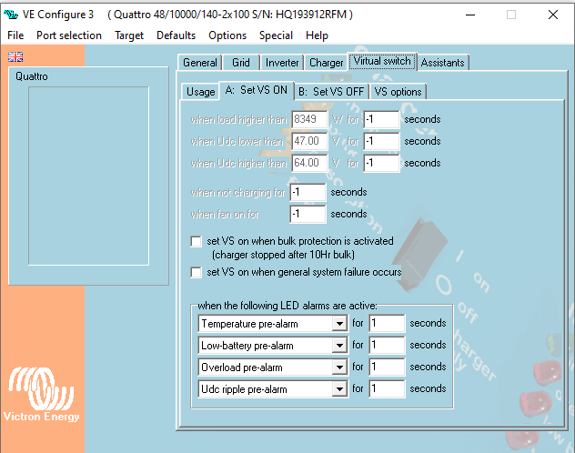
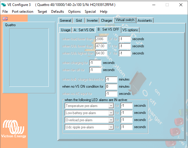
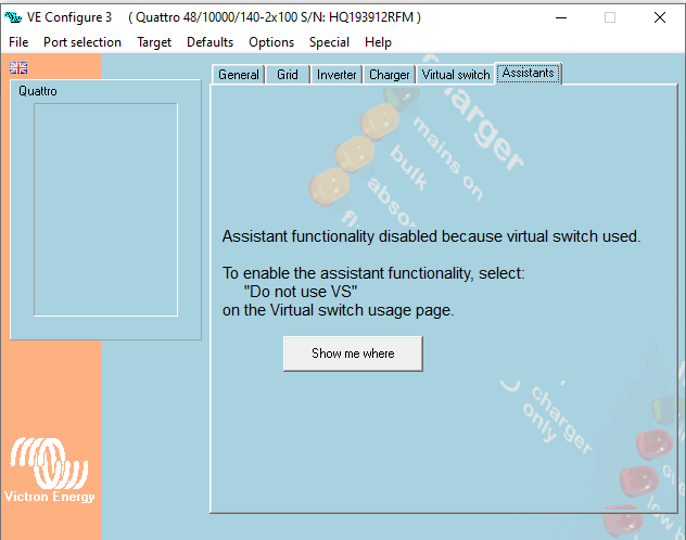
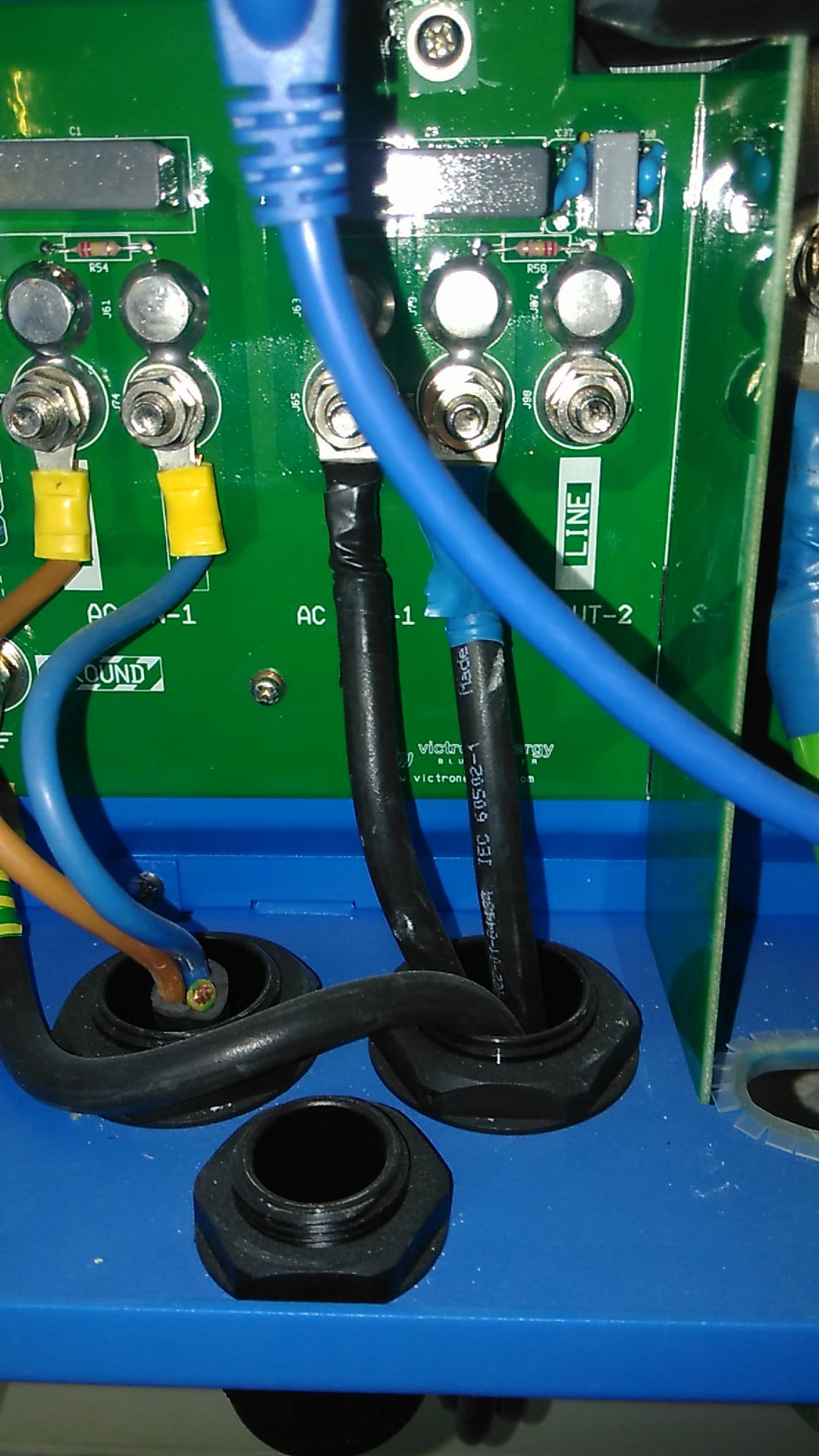
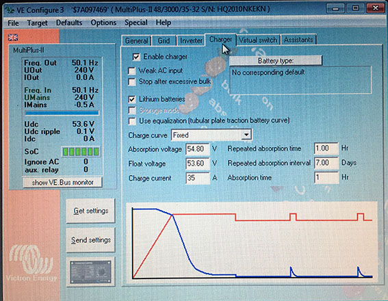
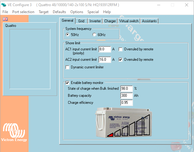
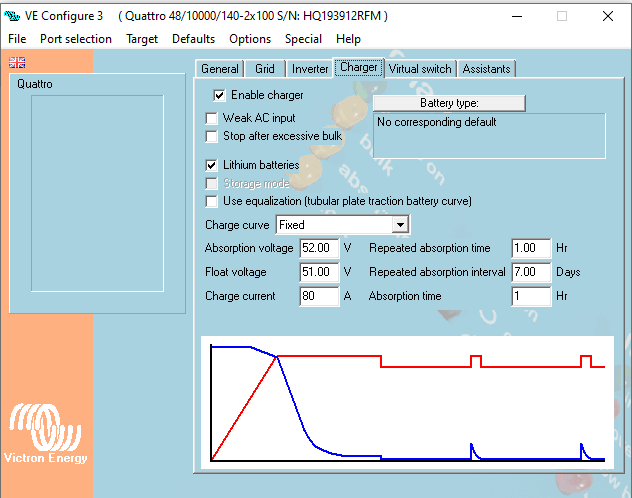
* Quattro 48/10000/140-2x100

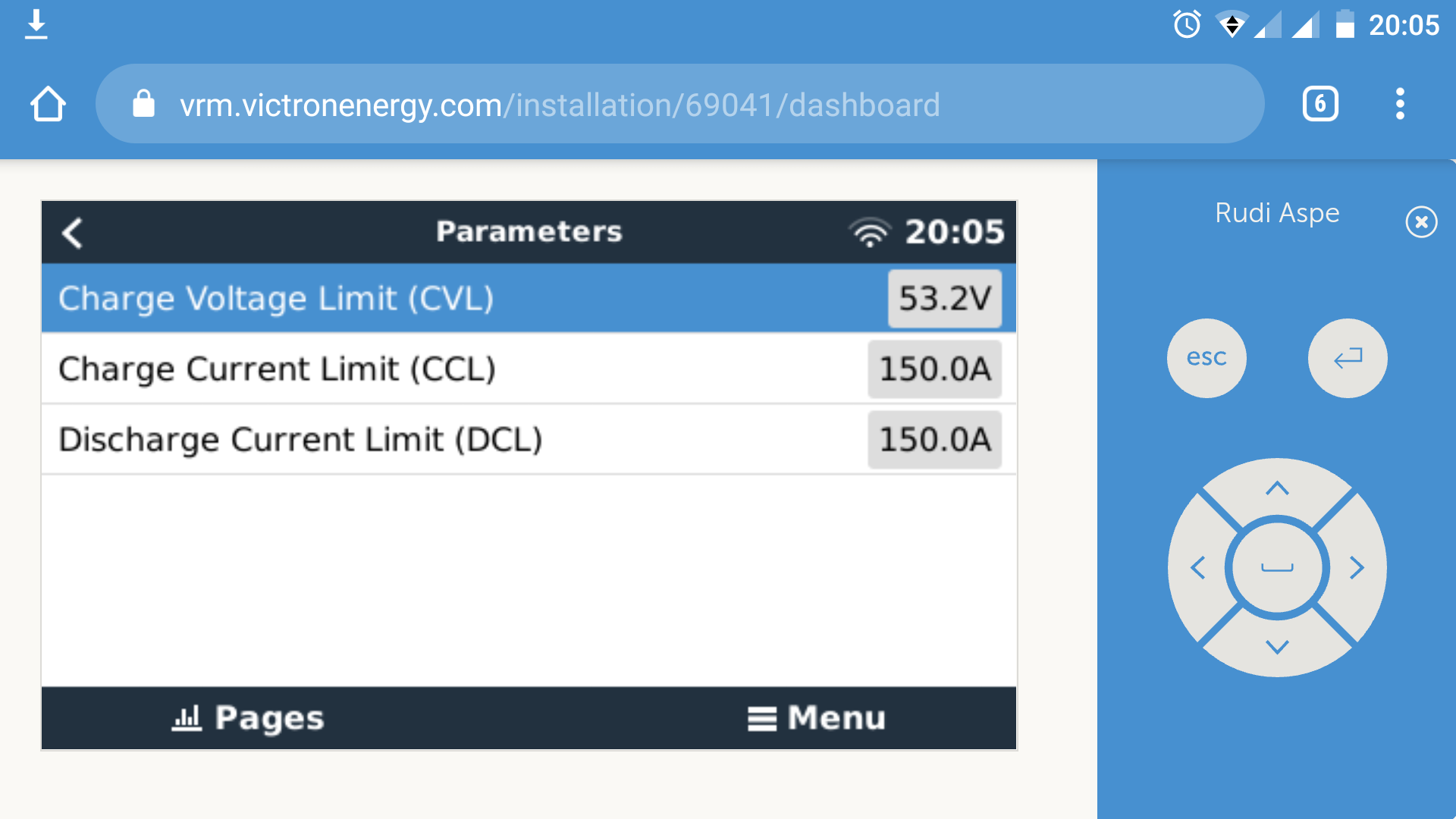
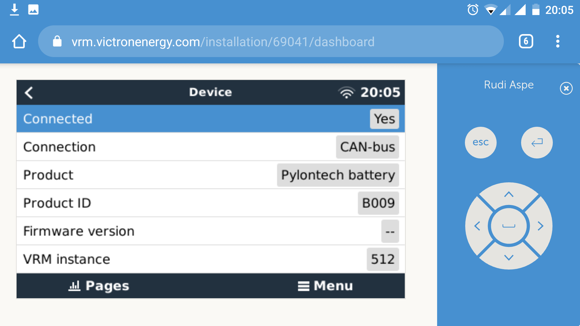
* 6 x 2.4kWh = 14,4kWh pylontech pack of batteries, good stuf

* Venus GX


The dashboard, at the moment, looks like this:

5.png


Facts/problems:


* Let's say that it's 1400hrs, the sun is shining bright, and the batteries are @ 60% and charging. Then, all of a sudden, the SMA stops putting electricity on the "grid". Often, the SMA sunny boy stops working for say 1 or 2 hours, losing critical energy in the winter and the end result is a battery that is say 80% charged instead of 100% at the end of the day.

So I checked out the statistics @ the moments that this type of scenario takes place (almost every day), check this out:


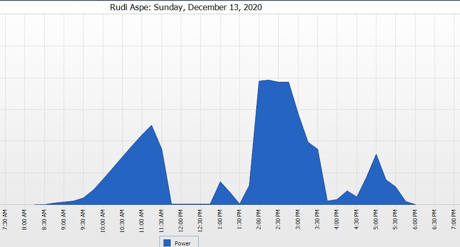
My father notices, for example December 13 (but this happens every day) that the Sunny Boy isn't putting power to the grid (He checks the Victron dashboard regularly, so he notices this quite soon), and he let's me know. So I start digging... And I notice this:

I notice that there are gaps in the production of the sunny boy.

2.jpeg


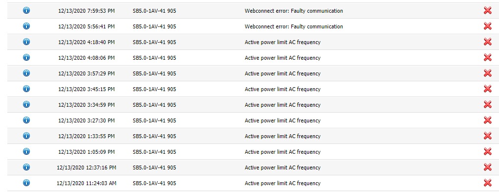
I check the SMA error page, and at the moments that there are gaps in the production, I get frequency related errors:

1.jpeg


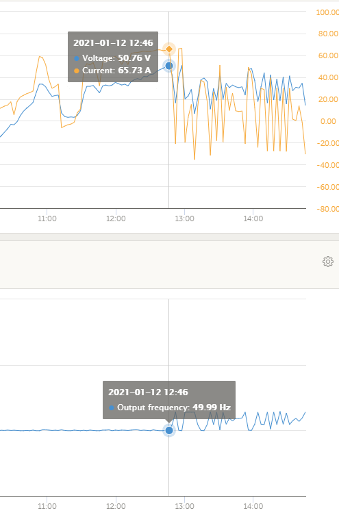
So I go the the VRM-app, and dig into the frequency statistics:

3.jpeg


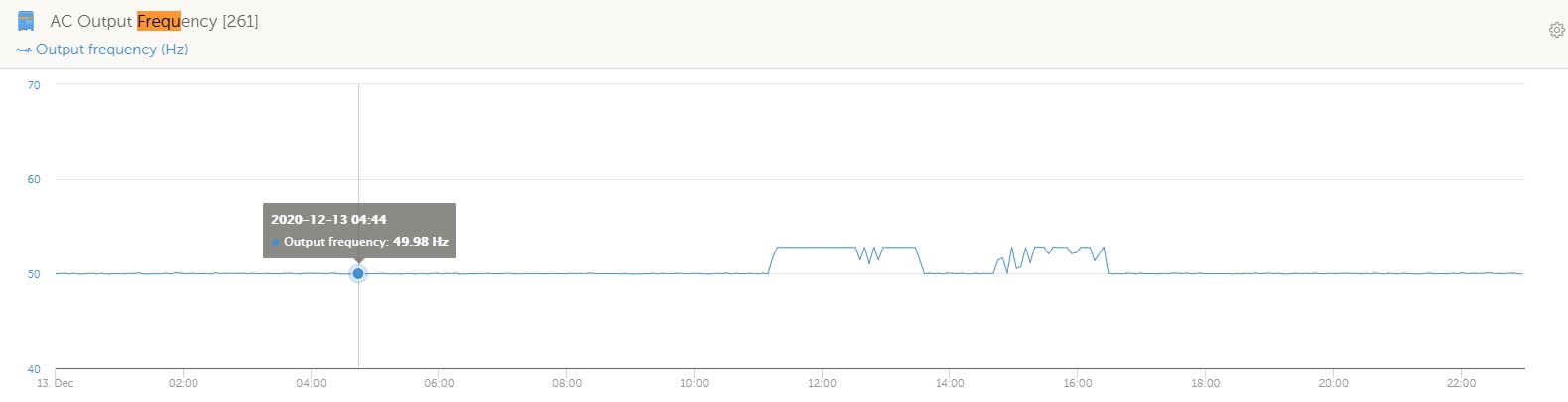
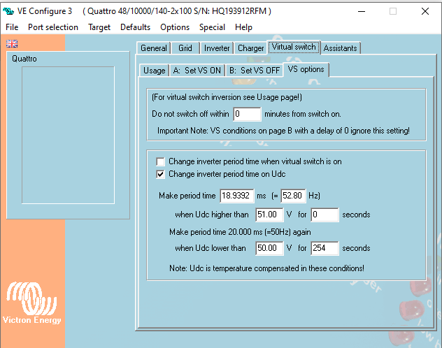
To me it's clear that something is causing ripples in the AC frequency (from for example 11AM-> 1300hrs, 53Hz, which isn't just a ripple).


My parents state that their bulbs start flickering, change brightness when these peaks/gaps occur.


* Initialy the installer installed a 6KW SAJ invertor, but this invertor got so terribly hot, that after a week or 2 it died. The installer then replaced the SAJ with a 5kW Sunny Boy. I told him (through my parents, I didn't actually get to talk to the installer) to install a 6kW invertor, because my parents paid for a 6kW, and 27 panels in Spain cán in fact generate more that 5kW. But the installer said that that is non sense, a 5kW was just fine.

-> What the F*c#??


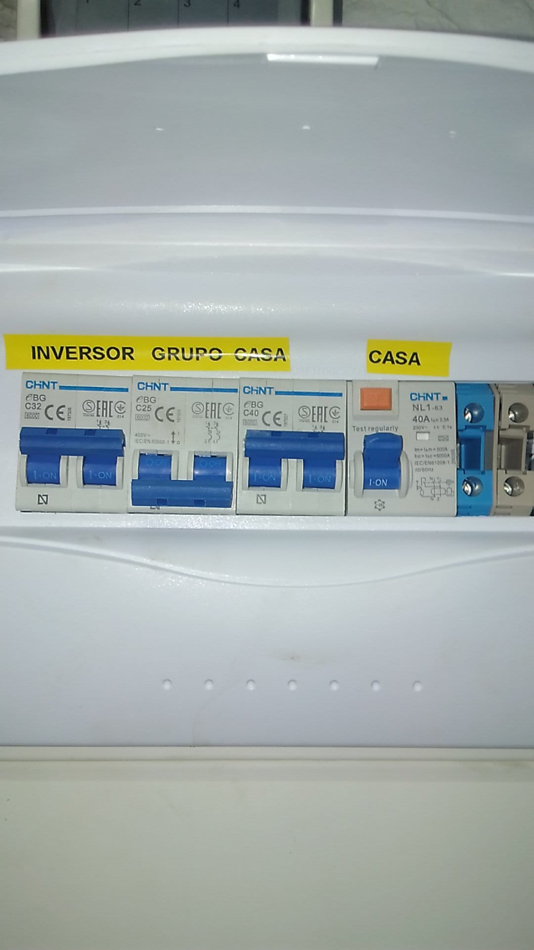
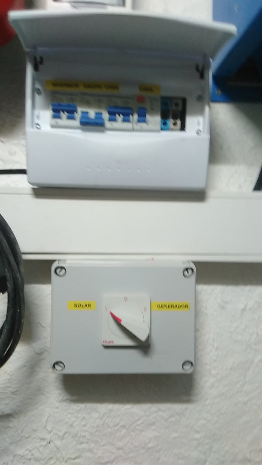
* The installer installed a 3-way switch for 'solar system', "off" and "generator".

4.jpeg

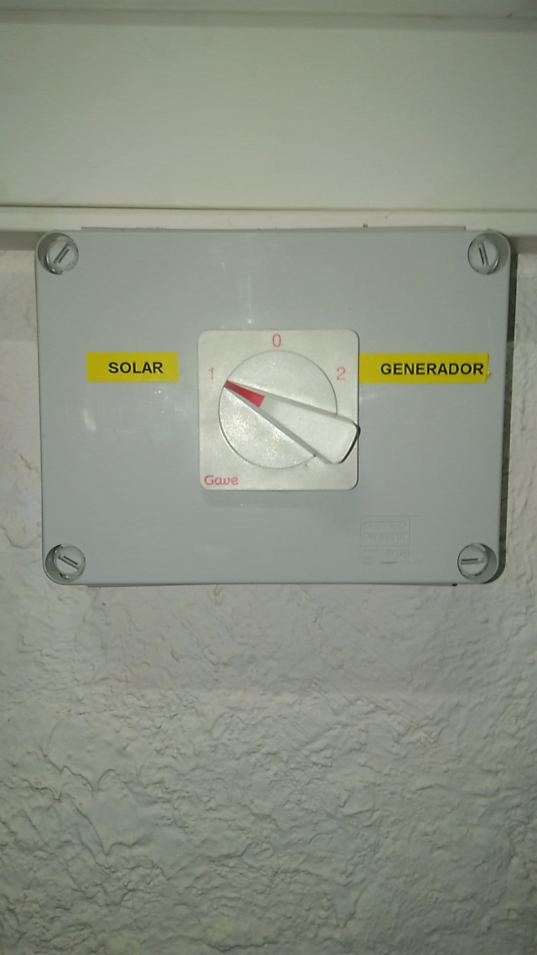
When my dad connected the generator and sets the switch to generator, all lights inside the house started to shine brighter, a couple of LED-stripts/bulbs "exploded", and the quattro started clicking like a maniac (must be relays trying their best to regulate something).

i believe they miswired the generator connection to the system. I think that my dad is putting 220V onto the system (with the generator), but the quattro is the master, not a grid tie invertor. Therefore the quattro doesn't synchronise it's 220V with the generators. The result is, I believe, constructive and destructive interference and as a result the bulbs exploded due to the AC peaks.

Does this seem likely to be the cause/what's happening?


What my parents want:

* to have as much and as stable of a 220V system as possible

* to have the invertors charge the batteries as fast as possible, without devices stalling for no reason (because the loose precious daylight in the mean time)

* to be able to connect my parents 6KW generator to the system to power the house and charge batteries in dark weeks without a lot of solar power;


That's it, and that's what's promised by the installer.


Please give my your thoughts. I'm watching all that is to be watched on YouTube, reading datasheets, etc. but actual help/opinions of guys witch real Victron knowledge would be invaluable.


Thanks in advance.


MultiPlus Quattro Inverter ChargerLithium BatteryGeneratorPylontechoffgrid
1.jpeg (88.4 KiB)
2.jpeg (72.6 KiB)
3.jpeg (34.9 KiB)
4.jpeg (101.3 KiB)
5.png (56.2 KiB)
2 |3000

Up to 8 attachments (including images) can be used with a maximum of 190.8 MiB each and 286.6 MiB total.

7 Answers
Guy Stewart (Victron Community Manager) avatar image
Guy Stewart (Victron Community Manager) answered ·

Hi @HDB,

It is always tricky to try and 2nd guess an installer, as they may have made design or configuration settings based on their own experience, or additional information that I do not have.

However, from the information you have presented, it would appear that there is some issue with how the Quattro is frequency shifting, and that it is occurring at a lower voltage than would be necessary to make full use of the AC PV to fully charge the Pylontech battery - shifting too early instead of ~53V.

I would first suggest that you watch the following Victron Training Programs and documentation to understand how the AC coupled system is intended to work from Victron's perspective, however there are other ways to do it, and those other ways might be more appropriate for site specific reasons. So I can not say that a mistake has been made.

There is an Online training here in English and Spanish specific to AC coupling.

Further there is a Fronius specific AC PV training here - though I know you are using an SMA inverter, there is some similarity - such as the use of the AC PV inverter assistant in an off grid system for a smooth ramp of the frequency, controlled by the DVCC messages from the managed battery for optimum charging.

AC PV documentation is here - https://www.victronenergy.com/live/ac_coupling:start

Once you understand that system, it may help then to have a closer inspection of the actual installation (not most, if not all, can be done remotely), and from there you will at least have some specific questions for the installer.

6 comments
2 |3000

Up to 8 attachments (including images) can be used with a maximum of 190.8 MiB each and 286.6 MiB total.

hdb avatar image hdb commented ·

Thanks for your reply.


However, from the information you have presented, it would appear that there is some issue with how the Quattro is frequency shifting, and that it is occurring at a lower voltage than would be necessary to make full use of the AC PV to fully charge the Pylontech battery - shifting too early instead of ~53V.


So a possible explanation might be that the charging voltage would get higher than a certain threshold, say 53V. If so, the Quattro raises it's frequency to 53Hz since this is a frequency that most invertors (Sunny Boy in this case) recognize as a shutdown signal.

I checked the charging statistics (charging voltage) for the same day,I also included the frequency:

6.png


One might think that 50.76V or so is the threshold voltage. Because at that moment the frequency jumps to 53Hz.

So I wondered where I could find this setting. Using Google I found out that I could export the Quattro configuration and open it locally (on desktop computer using VE Configure 3 to check the settings, which I did:


8.png


9.png


10.png


11.png


Does this data reveal anything? I see that the absorbtion voltage is set @ 52V, maybe changing this to 53V fixes it?

0 Likes 0 ·
6.png (46.9 KiB)
8.png (50.7 KiB)
9.png (17.2 KiB)
10.png (38.9 KiB)
11.png (30.0 KiB)

There are two other tabs at the top that you missed to post screenshots of, virtual switch and assistants.

Those tabs will be the ones that control the frequency adjustment of the AC PV.

Again though, please go through that AC PV training that I linked, and once you understand that, you will be in a much better spot to discuss what is going on with the installer.

In a managed battery system like the PYLONTECH, those charging values in VEConfigure aren’t used, instead those provided by the battery itself and then distributed to the system (MPPT and Quattro) by the GX device using DVCC.

0 Likes 0 ·
hdb avatar image hdb Guy Stewart (Victron Community Manager) ♦♦ commented ·

True, I didn't upload those because the "reply window" didn't let me upload more than x-amount of attachments. These are the missing screenshots:

12.png


13.png


14.png


15.png


17.png


In a managed battery system like the PYLONTECH, those charging values in VEConfigure aren’t used, instead those provided by the battery itself and then distributed to the system (MPPT and Quattro) by the GX device using DVCC. 

Based on this, I thought the same thing: no matter what I change, it's overruled by the DVCC (which indeed is enabled).


0 Likes 0 ·
14.png (40.1 KiB)
12.png (39.0 KiB)
13.png (39.3 KiB)
14.png (40.1 KiB)
15.png (27.9 KiB)
17.png (44.5 KiB)

That explains why the Pylontech battery is not fully charging from the AC PV.

The Virtual switch has been set up so that the AC frequency is increased once the battery voltage reaches 50V, disconnecting/ramping down the AC PV.

This is not the documented way to control an AC PV inverter in a Victron system, which is explained here -

https://www.victronenergy.com/live/ac_coupling:start

https://www.victronenergy.com/live/assistants:pv-inverter-support

So there is likely a reason that the installer has chosen to configure it in this undocumented way instead. Why it is like that, instead of using the AC PV inverter assistant is the question that needs to be understood.

One reason is that the installer was looking for a way to isolate the generator from the AC PV, so they were never active at the same time. There is another way to do this that does not cause the same issues you are seeing here with AC PV not generating when battery voltage is higher than 50V, and frequency shift causing generator connection issues, (for example, using AC-out-2 for AC PV, and setting rules that it is disconnected with AC input from the generator is detected).

It is hard to say for sure, but it also appears that the AC PV *might* be connected to the AC Input on the Quattro. This may also explain the three way transfer switch. If this is the way the AC PV is physically wired, then just changing the settings in VEConfigure will not be sufficient (and actually make it worse, by default the AC input connection is open, and then the AC PV will not be connected at all).


0 Likes 0 ·
hdb avatar image hdb Guy Stewart (Victron Community Manager) ♦♦ commented ·

I wasn't aware of this whole assistants-thing. It's amazing. Basically separate separate programd that run the whole time.


https://www.victronenergy.com/live/assistants:start


I'm digging further into the wunderfull world of Victron epuipment.


Thanks for the interesting feedback


0 Likes 0 ·
hdb avatar image hdb commented ·

Thanks by the way for all the usefull links. I'm not there yet, but learning a lot & quickly.

0 Likes 0 ·
seb71 avatar image
seb71 answered ·

I do not have experience with AC coupled systems, but from what I read, unless the AC coupled PV inverter is made by Fronius, the only way the Victron inverter (Multiplus or Quattro) can control (turn off) the AC coupled inverter is by raising its frequency to 53Hz. So maybe that is what happens in your case (for some reason, the Quattro inverter decides to turn the AC coupled inverter off). Or maybe I am wrong about this. Wait for other opinions.


The 1-0-2 switch is used strangely. I would use a 1-0-2 to switch between grid and solar, not between generator and solar, like in your case. You don't have grid, so I don't see why it's used. The generator should be connected to AC In 1 at your Quattro.

9 comments
2 |3000

Up to 8 attachments (including images) can be used with a maximum of 190.8 MiB each and 286.6 MiB total.

hdb avatar image hdb commented ·

Thanks for your useful insights.


I do not have experience with AC coupled systems, but from what I read, unless the AC coupled PV inverter is made by Fronius, the only way the Victron inverter (Multiplus or Quattro) can control (turn off) the AC coupled inverter is by raising its frequency to 53Hz. So maybe that is what happens in your case (for some reason, the Quattro inverter decides to turn the AC coupled inverter off). Or maybe I am wrong about this. Wait for other opinions.


So you are saying that by raising it's (= Quattro's) frequency to 53Hz, other grid tie invertors will recognize this as a signal to power off? So this is some form of analog communication between Quattro and (in this case) the Sunny Boy?

That's a genious way to let invertors communicate.


But this raises the question what makes the quattro shut down the Sunny Boy.

The 1-0-2 switch is used strangely. I would use a 1-0-2 to switch between grid and solar, not between generator and solar, like in your case. You don't have grid, so I don't see why it's used. The generator should be connected to AC In 1 at your Quattro. 

Exactly what I was thinking. Given that the Quattro has grid sensing / synchronising capabilities, I don't see a reason why one would connect the generator to the junction box (which obviously would mean that the 2 AC sources would be out of sync) instead of AC-IN-1.
It looks as if the installer wired the AC-IN-1 to a breaker called "generator" in the junctionbox, en the breaker is connected to the generator & the rest of the grid. That would mean they basically shorted AC-IN-1 and AC-OUT-1 with as a result the symptoms I described.

I would just connect the generator directly without the 3 way switch inbetween. The generator already is equiped with a 16amp breaker anyway....

0 Likes 0 ·
marekp avatar image marekp hdb commented ·
I would just connect the generator directly without the 3 way switch in-between. The generator already is equipped with a 16amp breaker 
anyway....

Make sure that this GEN is not DC type before you do that.

0 Likes 0 ·
hdb avatar image hdb marekp commented ·

6kVA 400V diesel generator with 16A 50Hz 220/230 ac output which I gave to him. Good machine.

0 Likes 0 ·
marekp avatar image marekp hdb commented ·

@HDB

Hi,

This is 3-phase 6kW GEN and you are using only 1 phase.

I am afraid that you can get only 2kW at 220V continuously.

0 Likes 0 ·
hdb avatar image hdb marekp commented ·

I know that it has a 16A breaker on the AC 220/230 input.


Even if your are correct with the 2kW capacity, would that be an issue? Shouldn't even a say, 1000W generator like a solar generator, work as a grid input AC-IN-1?


I've read https://www.victronenergy.com/live/multiplus_faq#generator_sizing


No matter the generator size, limiting the current shoud keep the generator happy, no?

0 Likes 0 ·
marekp avatar image marekp hdb commented ·

@HDB

Hi,

My comment was not related to your problem.

I only tried to make a point that fuel usage will be higher that it would otherwise be if you had 1-phase 2kW GEN.

As for where this GEN is connected I am still in the dark.

Why there is this switch (SOLAR-GEN)?

Why this choice?

Why SOLAR and GEN cannot be used at the same time?

No matter the generator size, limiting the current shoud keep the generator happy, no?

Yes, you can program the max current limit when GEN is attached to AC-IN of Quatro (you can evn have POWER ASSIST), but we do not know where this GEN is attached.

Regards,

Marek

0 Likes 0 ·
hdb avatar image hdb marekp commented ·

but we do not know where this GEN is attached


My dad has followed the wires from AC-IN-1, and they lead to the breaker that says "GRUPO", not to the switch (at least not directly).

I'll know for sure when I go thereimg-20210111-wa0012.jpg


img-20210112-wa0012.jpg


img-20210111-wa0015.jpg


0 Likes 0 ·
seb71 avatar image seb71 hdb commented ·

Going by the labels, I think that AC Out 1 from the Quattro goes to the C40 MCB (labeled Casa), then from here to the RCCB (labeled also Casa) and then it powers the house (casa).


You say that AC In 1 from Quattro is connected to one side of C25 MCB labeled Grupo. But what is connected to the other side of the C25 MCB (labeled Grupo)?


"Grupo" could be "Generator group"?


Also, what is connected to the C32 MCB labeled Inversor/Inverter? The AC coupled inverter?

0 Likes 0 ·
marekp avatar image marekp hdb commented ·

@HDB

Hi,

Can your dad ask this installer for some kind of diagram of this installation?

Regards,

Marek

0 Likes 0 ·
marekp avatar image
marekp answered ·

@HDB

Hi,

I do not know what settings should be for your LFP battery made by Pylontech but mine LFP made by Winston have higher voltages set in VEconfigure.

4.jpg

The other interesting thing about your setup is that 3-way switch (PV-GEN).

It suggests that the GEN is not connected to Quatro, as it should, but to MPPT.

The GEN should be of DC variety to be able to do that.

It would help if you posted here the system schematic with specification or model of this GEN.

Regards,

Marek


4.jpg (117.2 KiB)
12 comments
2 |3000

Up to 8 attachments (including images) can be used with a maximum of 190.8 MiB each and 286.6 MiB total.

hdb avatar image hdb commented ·

You think exactly the same thing as I do.

I'm unable to go to spain, so I'm asking my father to go and check the things I ask him to check.


It sounds as if AC-IN-1 is (accidentely?) shorted with the 220V junction box in the house, which would explain the Quattro going crazy when the generator is started.

I therefore advised my father to disconnect whatever is connected to AC-IN-1, and directly connect the generator to AC-IN-1 without the 3-way switch. I believe that will resolve the generator issues.


That being said: the generator problem has nothing to do with the SMA Sunny Boy shutting down for no reason.


Check out my respons to steward for screenshots of the VE configure. I bet if a played a bit with the absorbtion and/or float voltage, I could fix the issue. But I'm waiting to change anything a little longer, first I want the advice / more feedback of you guys. I'm still a rookie, learning Victron as I'm typing....

0 Likes 0 ·
marekp avatar image marekp hdb commented ·

Based on what I have, I thing those voltages are to low.

I have Winston cells with BMS that is unsupported by Victron but cell chemistry is the same. (LFP)

Check with the Pylontech setup instruction.

As for that switch (1-0-2) it is very suspicious that is labeled SOLAR-GEN.

There should be no connection between solar circuit and AC from GEN.

The only connection I see is when the GEN is DC type and its is connected to MPPT input of solar inverter when there is no sun for PV panels. Hence the switch.

The solar inverter gets DC from GEN instead from PV panels.

Maybe this GEN is not good enough for AC-in1 on the Quatro so the AC from it got rectified and routed to MPPT.

Very unusual.

It is also possible that this switch disconnects the solar inverter AC output from Quatros AC-out and connects the AC GEN in its place. This is also unusual.

WE need a schematic.

0 Likes 0 ·
seb71 avatar image seb71 marekp commented ·

Plyontech ufortunatelly only uses 15 cells in series (for a 48V nominal battery), instead of the normal 16 cells. So you have to account for that when comparing battery voltages.

0 Likes 0 ·
marekp avatar image marekp seb71 commented ·

You are right.

Pylontech uses 15 cells.

This is why I suggested to follow Pylontech instructions.

https://www.victronenergy.com/live/battery_compatibility:pylontech_phantom

0 Likes 0 ·
hdb avatar image hdb marekp commented ·

If I had a schematic, I would give it. :-)


It's a 6KVA 400V diesel generator with a 16A 220/230V 50Hz plug. So my dad connected this to the 'generador' part of the switch, as instructed by the installer. But I'm quite sure that this puts generator AC onto the grid, unsynchronized...

If that's the case, the installer is worth F&c+ing nothing.

0 Likes 0 ·
hdb avatar image hdb marekp commented ·

Check out these screenshots, maybe they help:

screenshot-20210112-200529.png

screenshot-20210112-200547.png

0 Likes 0 ·
hdb avatar image hdb hdb commented ·

Please help me understand something:


Victron says:


When DVCC is enabled, the battery (via the CAN-bms) is responsible for the charge voltage. The Pylontech battery requests a charge voltage of 53.2V. We have however found that in practice this is too high.

The Pylontech battery has 15 cells in series, so 53.2V equates to 3.55V per cell. This is very highly charged and makes the system prone to go overvoltage.

It should also be noted that a LiFePO4 cell stores very little additional energy above 3.45V.

For this reason we opted to override the BMS and cap the voltage at 52V. This sacrifices almost none of the capacity and greatly improves the stability of the system.

Source: https://www.victronenergy.com/live/battery_compatibility:pylontech_phantom?do=export_pdf


But check out my screenshot above: CVL (Charge Voltage Limit) is set @ 53.2V.


I understand that the Pylontech-system gives it's preferred parameters to Venus GX through CAN. That's why I see 53.2V (Pylontech set the Venus to 53.2V).


Yet, do I understand correctly that, allthough I see 53.2V set, "behind the scenes" the CVL is set/topped off to 52V because experience & reality proved that this is a better and more stable value? So Vitctron basically hardcoded this overrule into their system?


0 Likes 0 ·
seb71 avatar image seb71 hdb commented ·

From your screenshots, the voltages from the charger from your Quattro are set correctly.

Check if the MPPT is also set correctly.


Off-topic:

This Victron forum with reply (comments) branches is hard to follow when there are longer threads. Classic forums are the best.

0 Likes 0 ·
marekp avatar image marekp seb71 commented ·

Hi,

This Victron forum with reply (comments) branches is hard to follow when there are longer threads. Classic forums are the best.

I agree.

Following many threads is almost impossible here.

Even following posts in one thread is difficult when automate hides longer exchanges.

Regards,

Marek

0 Likes 0 ·

Hi @HDB,

I would definitely NOT advise that any changes are made until it is fully understood how the system is wired.

It may be DANGEROUS to do so. Just as an example it could be that the SMA PV is connected to the AC-input, and that AC-input has been programmed to remain permanently connected and used to shift the frequency. That would also explain the strange noises when trying to connect the generator.


Do not do any re-wiring of the system until it is fully understood.

Far better before touching anything, to take a pen and paper and trace out where all the wires are connecting. Draw your own system wiring diagram from how it is actually connected. Also do the training on both MultiPlus and AC PV, to understand how they behave.

0 Likes 0 ·
hdb avatar image hdb Guy Stewart (Victron Community Manager) ♦♦ commented ·

I'm not going to let my father modify the installation. Nobody touches the installation. I'm just trying to figure out what's wrong with it, with the (limited) info that I have.

0 Likes 0 ·
hdb avatar image hdb commented ·

Do you have DVCC enabled?

0 Likes 0 ·
kimmo-paukku avatar image
kimmo-paukku answered ·

Hi,

Sorry my bad English. Please check all correct values from Victron & Pylontech UP2500, US2000, US3000, Phantom-S & Force-L1 manual. It seems, that some values are slightly off right now.

Also adjust battery capacity. You said, you have 10kW pylontech battery rack. If you are using Pylontech 2,4kW batteries, those are about 50Ah each, so you have total capacity 200Ah, not 300Ah. That can/will mess up SOC calculation. With Quatro 10kVA inverter (Off grid) there should be at least 7pcs of 2,4kWh batteries.

That 1-0-2 switch can be also for Inverter bypass control. If your Quatro will die totally from some reason, there must be a chance to bypass this system. But then there much be also installed additional contactors for this function. There must be also contactor installed on Quatro AC out, so its not possible to back feed from generator to the inverter. (all depends how this system is build and how generator is connected). It sounds without knowing any details, that quatro and generator is now connected parallel without sync and generator back feed to the quatro. What will happen, if you switch your PV system totally off, and then switch to the generator .... doest it work ?


3 comments
2 |3000

Up to 8 attachments (including images) can be used with a maximum of 190.8 MiB each and 286.6 MiB total.

hdb avatar image hdb commented ·

Thanks for your reply. It's a 6 times 2.4kW system. US2000 modules.


0 Likes 0 ·
marekp avatar image marekp hdb commented ·

So it is 300Ah battery but 14.4kWh and not 10kWh.

0 Likes 0 ·
hdb avatar image hdb marekp commented ·

True, I mentionned initially in the first pust that it was 10kWh or so, didn't know how mucht exactly. It turns out to be 14.4kWh.

0 Likes 0 ·
hdb avatar image
hdb answered ·

My dad has asked for the schematic. I'll keep you guys posted. Thanks for the help.

2 |3000

Up to 8 attachments (including images) can be used with a maximum of 190.8 MiB each and 286.6 MiB total.

hdb avatar image
hdb answered ·

I received the schematic.schema anoniem.pdf


schema.png (82.2 KiB)
schema-anoniem.pdf (116.0 KiB)
esquema-unifilar.pdf (137.7 KiB)
schema-anoniem.png (120.4 KiB)
7 comments
2 |3000

Up to 8 attachments (including images) can be used with a maximum of 190.8 MiB each and 286.6 MiB total.

marekp avatar image marekp commented ·

It is something but important information is still missing.

There is nothing about the connections inside this CONMUTADOR empty box.

0 Likes 0 ·
hdb avatar image hdb commented ·

I asked the installer in Spanish:


"Could you also explain why?

* You used a "virtual switch" instead of using the "AC PV Inverter Wizard".

* What is connected to the Quattro AC-IN-1: the generator or the SMA Sunny Boy "

* Given that DVCC is enabled I don't see why you want to overrides the 53.2V which is default for pylontech batteries. Victron already overrides the 53.2V standard, which pylontech tells the Venus GX using CAN, automatically at 52.4V as mentioned in the article. (i gave him the pylontech-vicron article).

--> He answered:

* The way to regulate solar production is through the frequency variation of the grid inverter (SMA in this case), with the data shown on the attached screen. It could also be tried as indicated with 'Assistant of photovoltaic AC inverter', however, as far as I know, it is the same.

* As you can see in the diagram in the AC-In the group is connected.


--> I responded:


I believe that the AC-IN-1 (grupo) is shorted to the AC-OUT which explains the extreme clicking sounds (relays trying to synchronise waves) in the quattro when the generator is started.


* Also, have you limited the AC-IN-1 current in VE Configure? It should be limited to, say, 16A, for the generator. Otherwise the generator will not be able to provide the ammount of current that the batteries will draw when charging.

* Why didn't you just supply a connection for my father to connect his generator into, directly and uniquely to AC-IN-1? I believe that there may have been some miswiring in the "COMMUTADOR"-box. The connection between "AC-IN-1" and "COMMUTAOR" seems unnecessary and may even be the cause of the generator/quattro-clicking sounds.

* Why do you limit to 51V even though the pylontech batteries mention 53.2V in their manual? I believe that changing the Virtual Switch options to 53.2V instead of 51V may solve the interuptions caused by the 53Hz increase (which shuts down the SMA to soon).

* According to SMA literature, 52HZ might suffice as a frequency increase (cf.https://www.sma-sunny.com/wp-content/uploads/2016/12/SB-OffGrid-TI-en-42.pdf) . This may reduce flickering of light bulbs that use PWM (pulse width modulation) as mentioned by my parents as a noticable problem.

*

Also,


The use of the "PV invertor support assistant" is advised by Victron as the default way to regulate another inverter (~ Frequency shifting) to limit battery overvoltage situations.

Could you please consider using the assistant instead?


0 Likes 0 ·
marekp avatar image marekp hdb commented ·

Hi,

Did this installer explain why the GENSET is not connected to AC-in on Quatro?

Why he installed this extra "CONMUTADOR" if one is already included inside Quatro?

For his way, your parents did not have to pay more for Quatro because MultiPlus i cheaper.

0 Likes 0 ·
hdb avatar image hdb marekp commented ·

I'm waiting for his response to my latest questions. Do you agree with the questions I asked him?

0 Likes 0 ·
marekp avatar image marekp hdb commented ·

I do not have experience with Pylontech. It surprised me that they use 15 cell setup.

The important question is that about the GEN connecting.

You can also ask him, why he did not use Fronius which works perfectly with Victron?


0 Likes 0 ·
hdb avatar image hdb marekp commented ·

https://www.victronenergy.com/media/pricelist/Pricelist_Victron_2021-Q1_Euro_C.pdf


AFAIK there is no 10kW Multiplus, and 2 5kW Multiplus devices are more or less the same in price as 1 10kW quattro

0 Likes 0 ·
marekp avatar image marekp hdb commented ·

As per price list:

Quattro 48/10000/140-100/100 - € 3.778
MultiPlus-II 48/5000/70-50 - € 1.612

Two MP-II are over 550 Euro cheaper than one Quatro.

Also if you, later on, would like to increase power you can add third MP-II.

0 Likes 0 ·
hdb avatar image
hdb answered ·

Dear All,


I suggested to the installer to remove the virtual switch and replace it with the AC Invertor Assistant.


This fixed the problem (batteries not charging as it should).

The generator problem: not solved yet. But I'm sure the installer shorted AC-IN-1 with the AC-OUT somwhere in the general junction box through the 1-0-2 switch. I'll fix that myself when I get to Spain.


I'm "closing" this topic. I'm going to install a second battery bank @ my parents, more on that in new topic.

2 |3000

Up to 8 attachments (including images) can be used with a maximum of 190.8 MiB each and 286.6 MiB total.