There is no current or power coming through on my BMV 712.
Does that mean the wiring is wrong?
Or has it been set up incorrectly?
Any help greatly appreciated, my installer is not around.
connected to 24 x REXC 600 Lead Carbon batteries.
asked
BMV 712 - no current or power
Thank you all so much for your input, I really appreciate it!
Here are some photos of the wiring, I also have a temperature sensor in there somewhere but I can not see it, I think he may have put it into the centre the battery bank.
On closer inspection, there seems to be a small blue wire that is cut, could this be it?
Thanks, Caroline


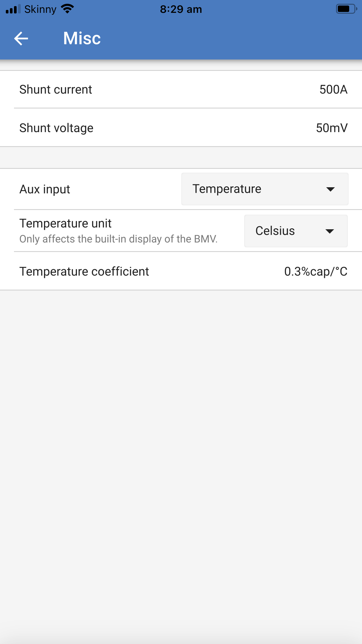
Here are some pics of the settings.
The electrician said the wiring he did was correct %100
Thank you so much @Seb71
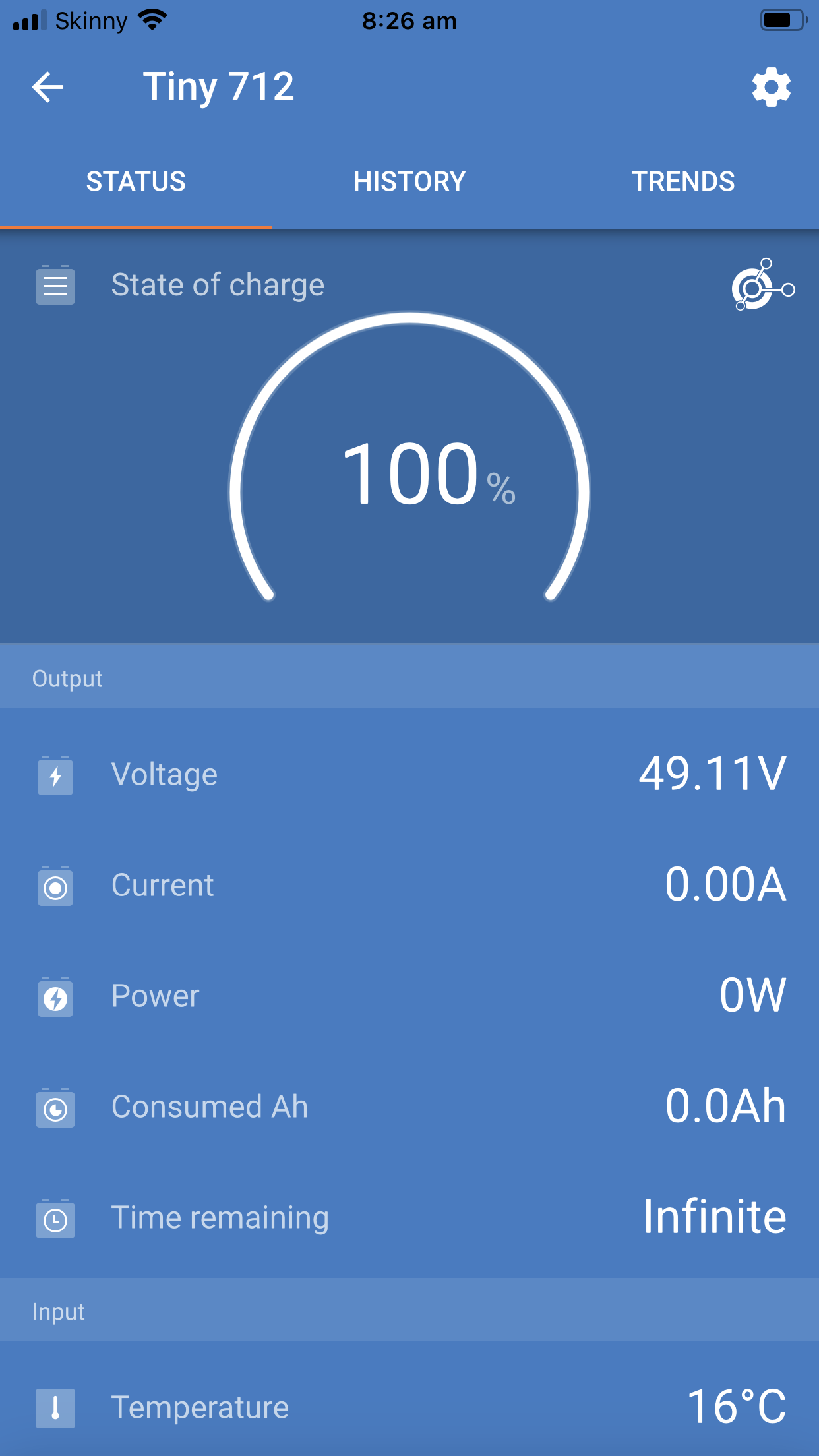
So you have something charging or discharging the batteries and the BMV still shows 0A?
Hi ! In my opinion, it is a bad wiring done by your electrician. He has probably connected the - (minus) in a way that the battery charge / discharge is not calculated.
Michel
What do you have connected? Inverter? Solar chargers?
Do you have a disconnect switch for those?
Disconnect everything from the batteries, except the BMV shunt.
Then press the "Calibrate" button (from "Zero current calibration"). It's a long shot, but maybe it was pressed while charging with constant current for instance.
I don't think so. A charging current is never 100% the same over a long time. it always goes up and down a bit.
Probably.
But if the wiring is correct (as he claims), then the only remaining possibility is that he has a defective BMV,
There are so many questions about that topic here in the community and most of them said "everything is wired correctly like in the manual" but most of them had a wiring issue.
We also get many mails and calls from costumers with the same problem and in most cases it was a wrong wiring.
Of course, the obvious, maybe......is the shunt connected properly? One (and only one) neg cable between battery neg and battery side of shunt, and all other negative leads connected to the load side of the shunt, either directly to that side of the shunt, or via one cable connected to a negative bus bar and all negative leads coming off that bus bar??
Thank you all so much for your input, I really appreciate it!
Here are some photos of the wiring, I also have a temperature sensor in there somewhere but I can not see it, I think he may have put it into the centre the battery bank.
On closer inspection, there seems to be a small blue wire that is cut, could this be it?
Thanks, Caroline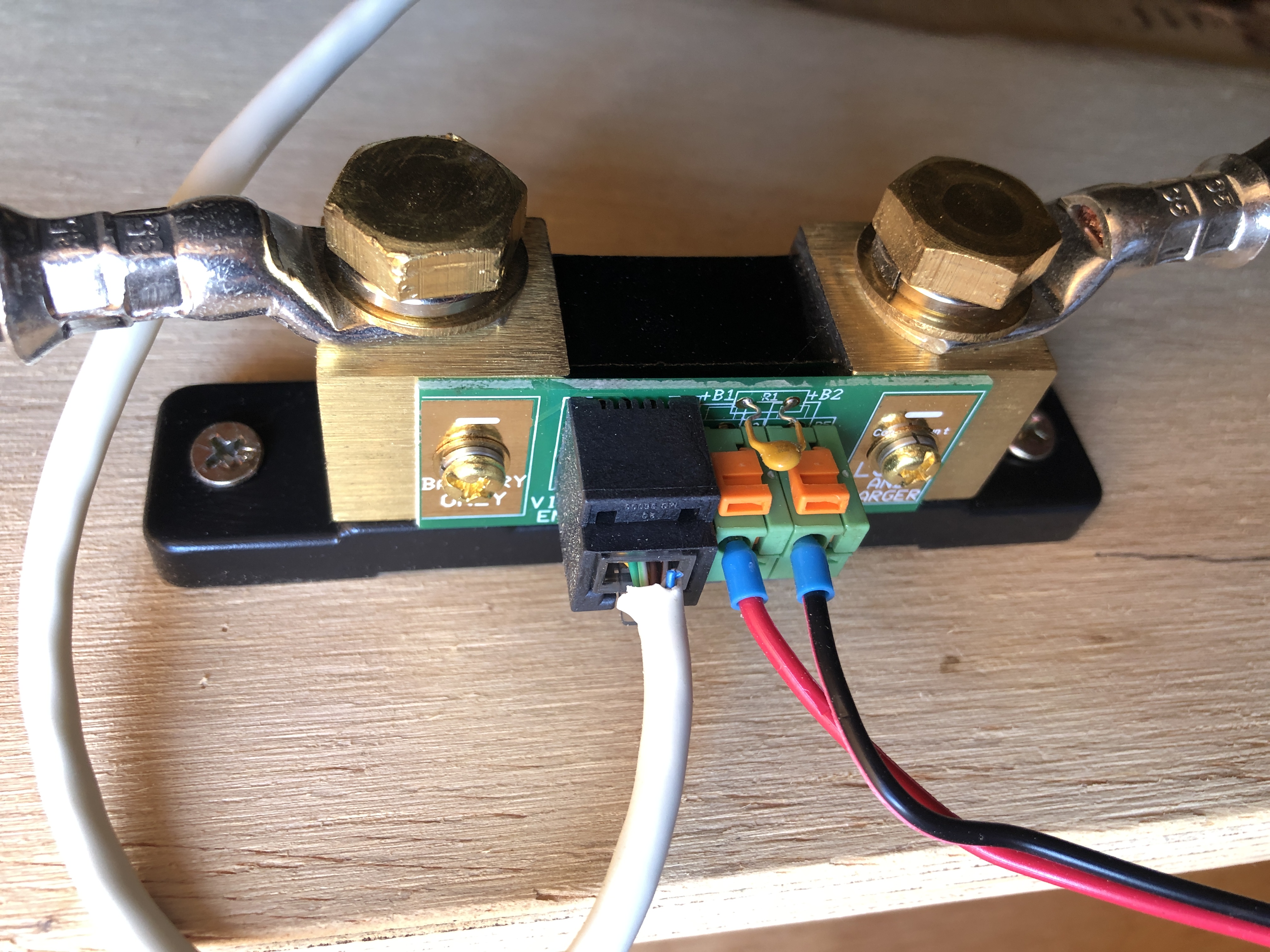
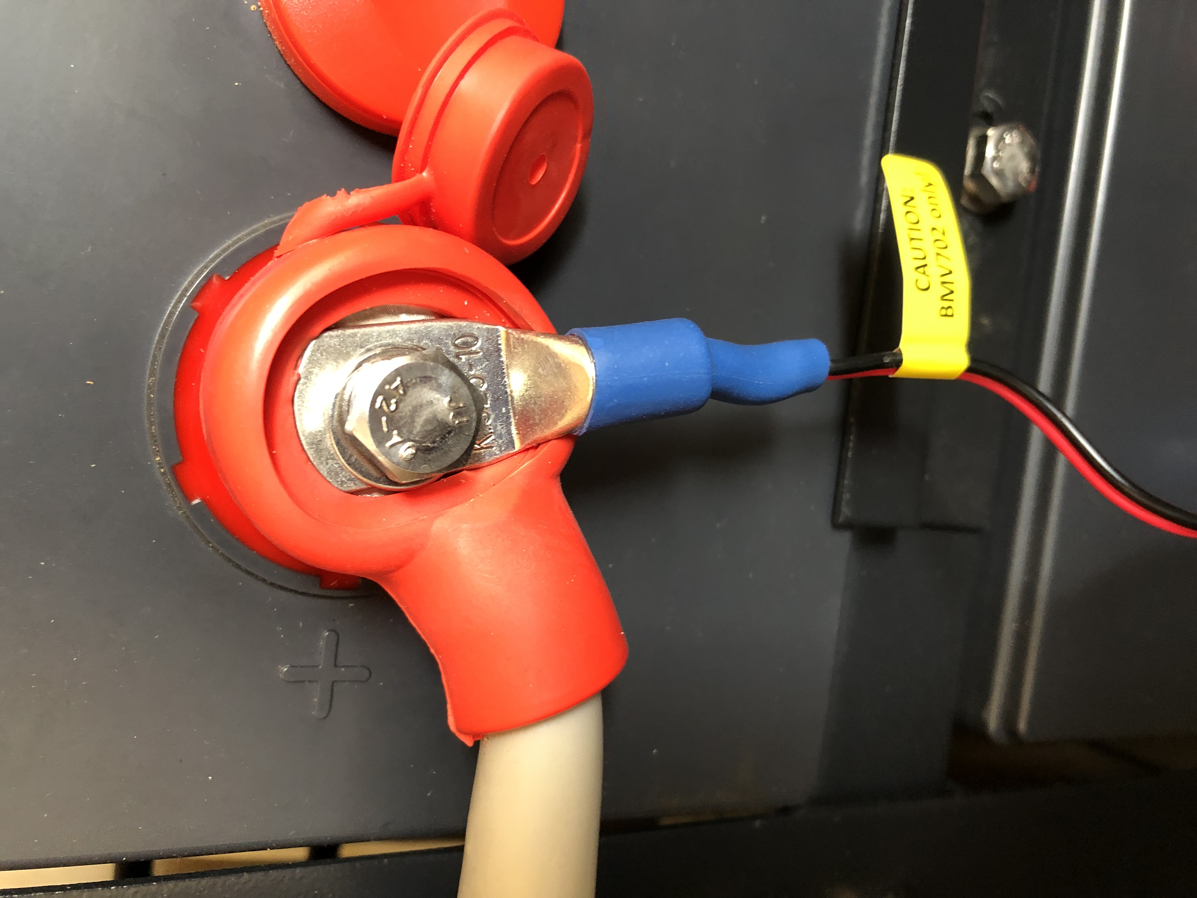
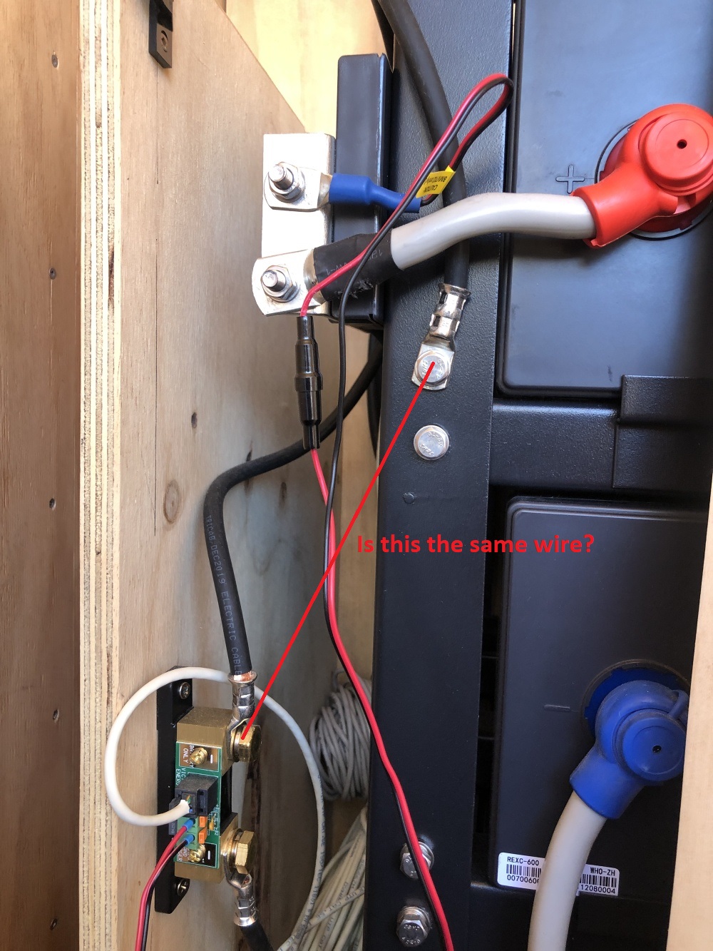
The photo appears to show the negative battery terminal connected to the load side of the shunt - it should be connected to the terminal marked "battery only".
Could you check this is correct, or is it the photo and a bit hard to see 100%?
The other side of the shunt appear to be connected to the battery housing metal but I cannot see where the appliance negatives are connected.
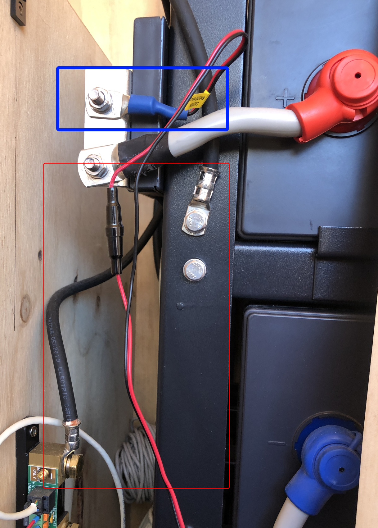
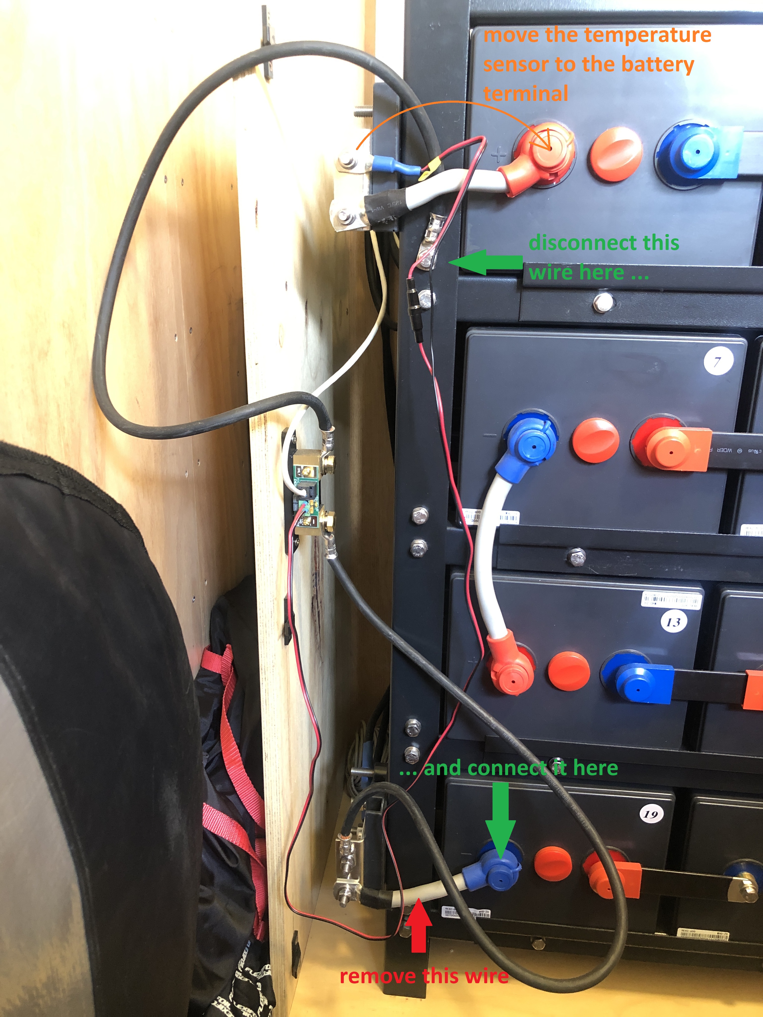
The temperature sensor is the device I have highlighted in blue on the pic below. It should be located on the battery terminal.
Do you have anything connected to the battery? Chargers? Loads? Are they working?
Could you get some more pics?
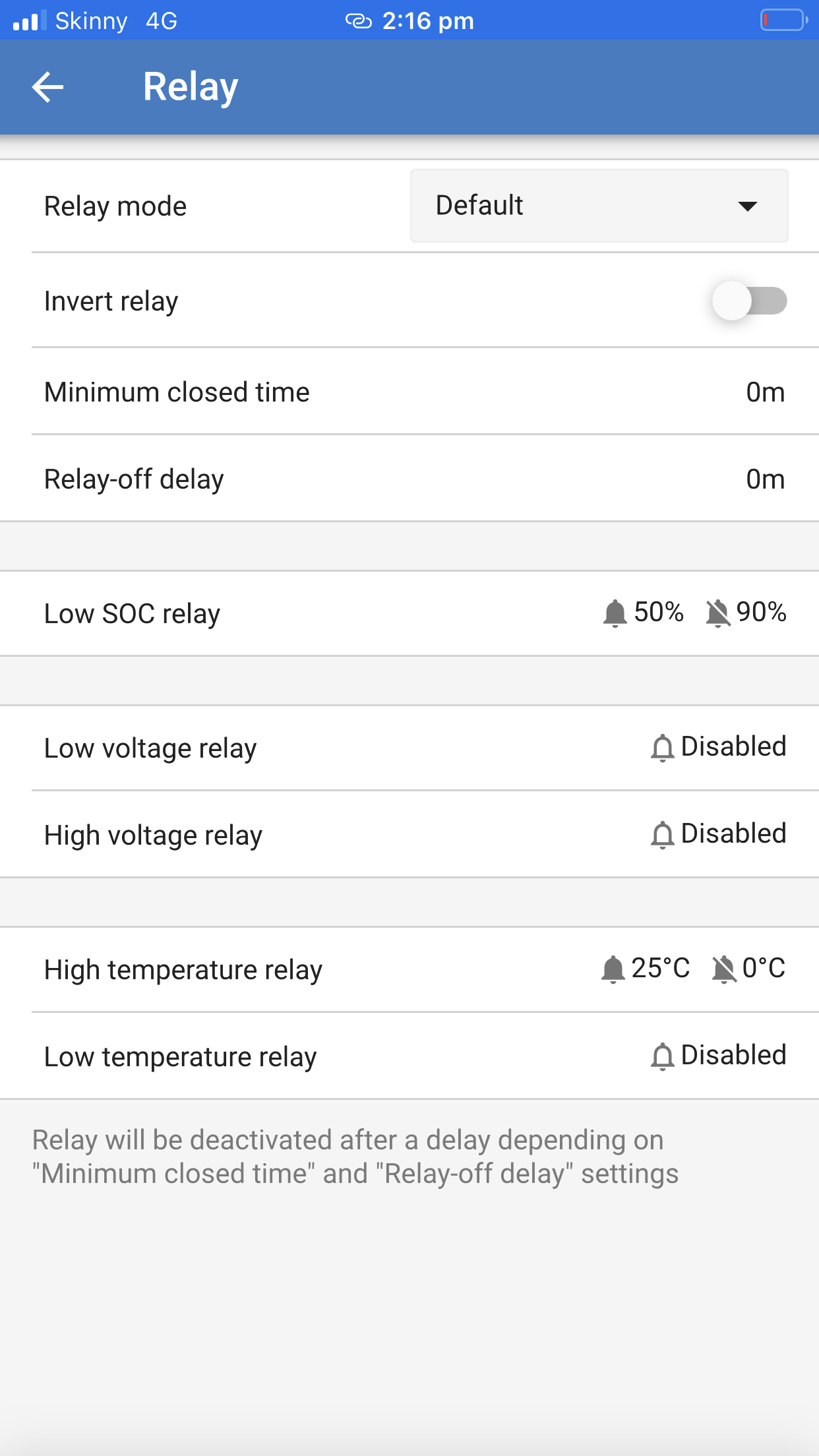
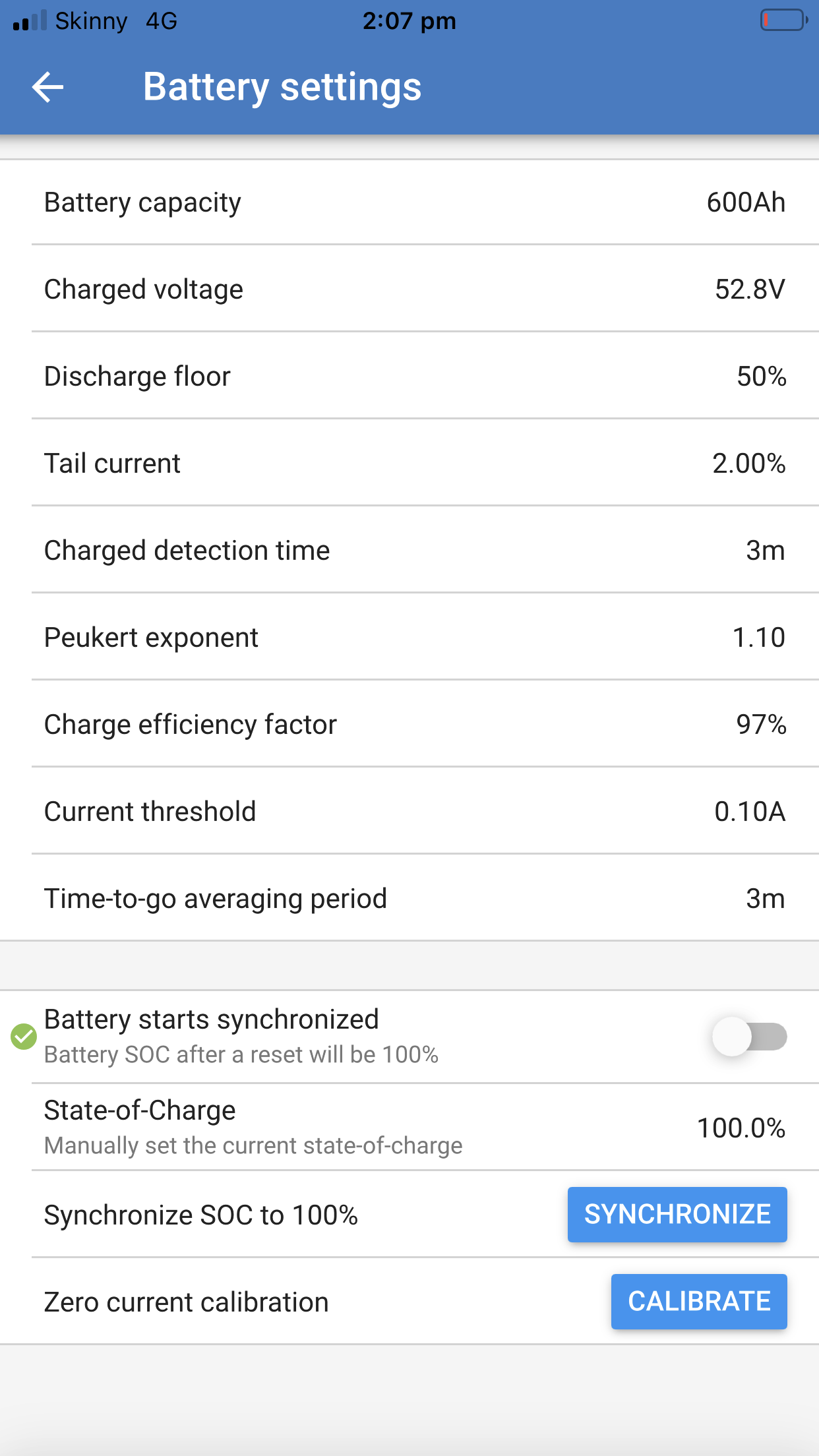
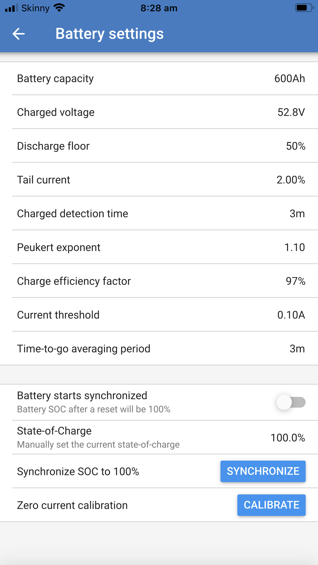
There also appear to be a number of the settings incorrect, too - like charged voltage, charge efficiency factor and Peukert exponent for the type of batteries you have, but these wouldn't stop current measurement, just the accuracy of the meter.
Thank you so much for your assistance on this, that was a terrible photo I posted, so here is a better one, my apologies.
Can you please tell me the correct settings for the BMV 712 monitor which best suits the Lead carbon Batteries I have, that would be really helpful.
I am not able to contact the electrician at this time of the year, I would love to be able to fix this myself and I do feel I am able, with right instructions.
I need to know if I should turn everything off first?
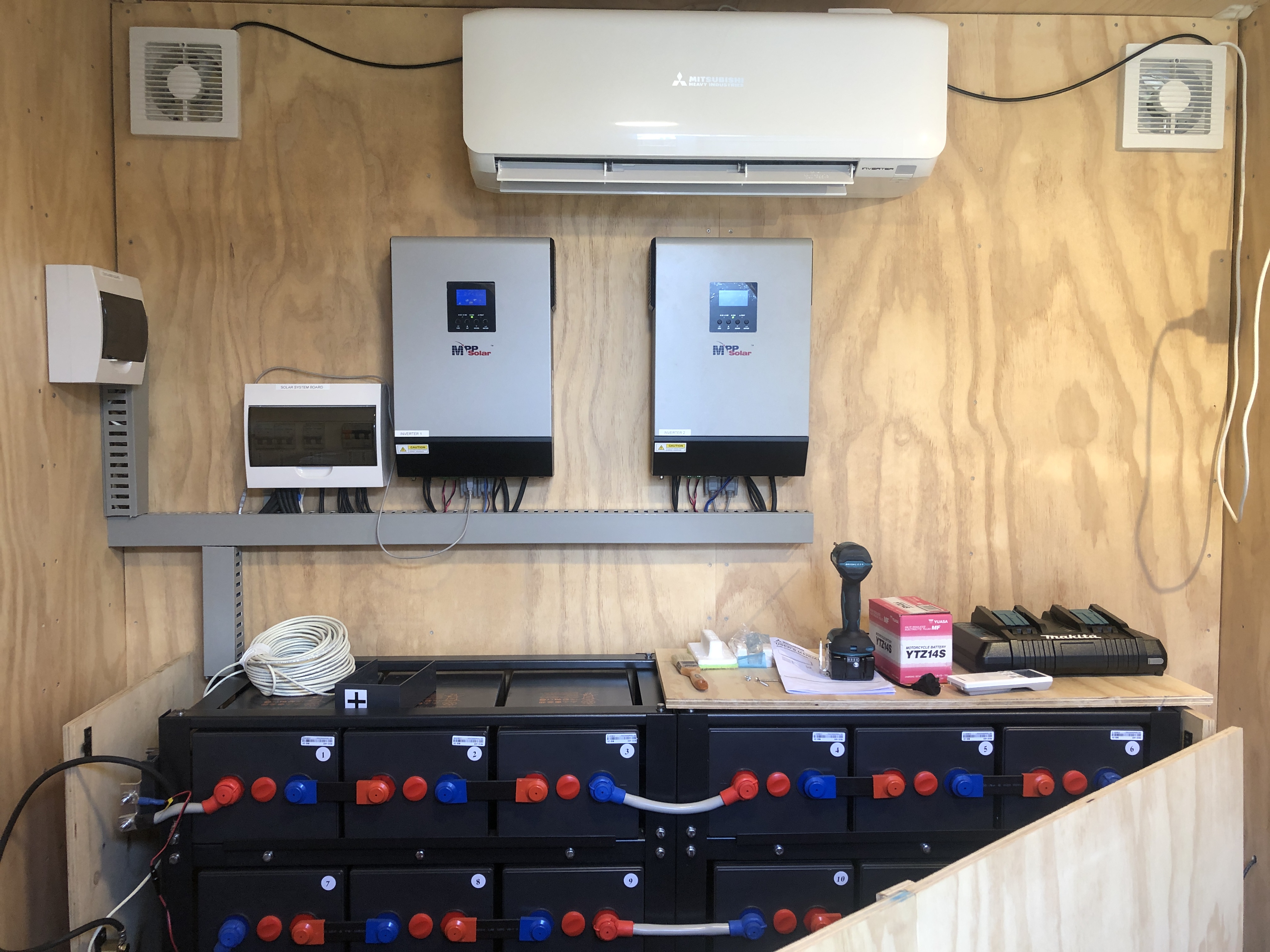
I have 2 x 5k inverters running from the batteries and 9 x solar panels, also have my generator connected that kicks in when batteries are low, that happened the other day so I know that is working.
Thanks so much, I really appreciate this.
Caroline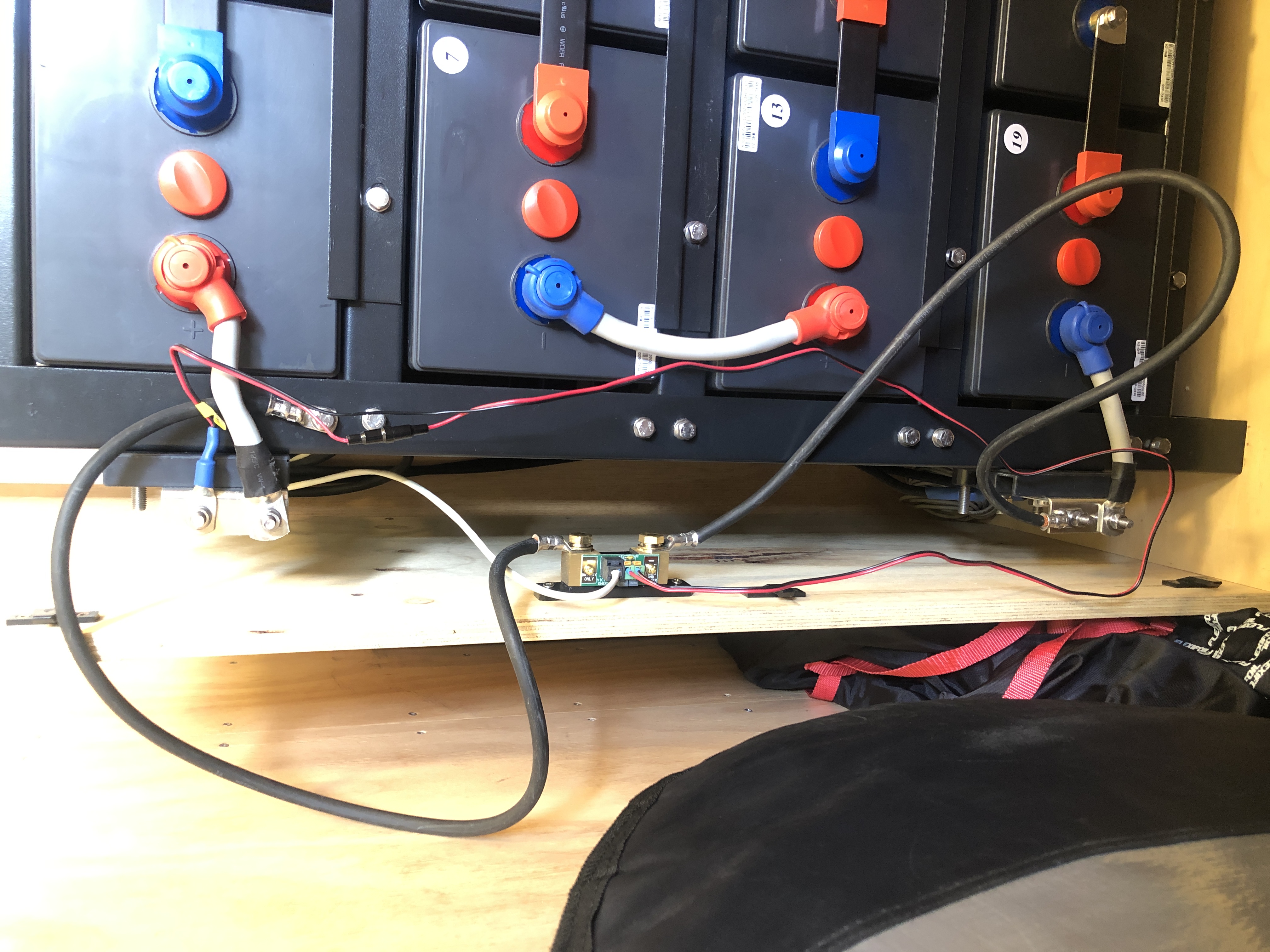

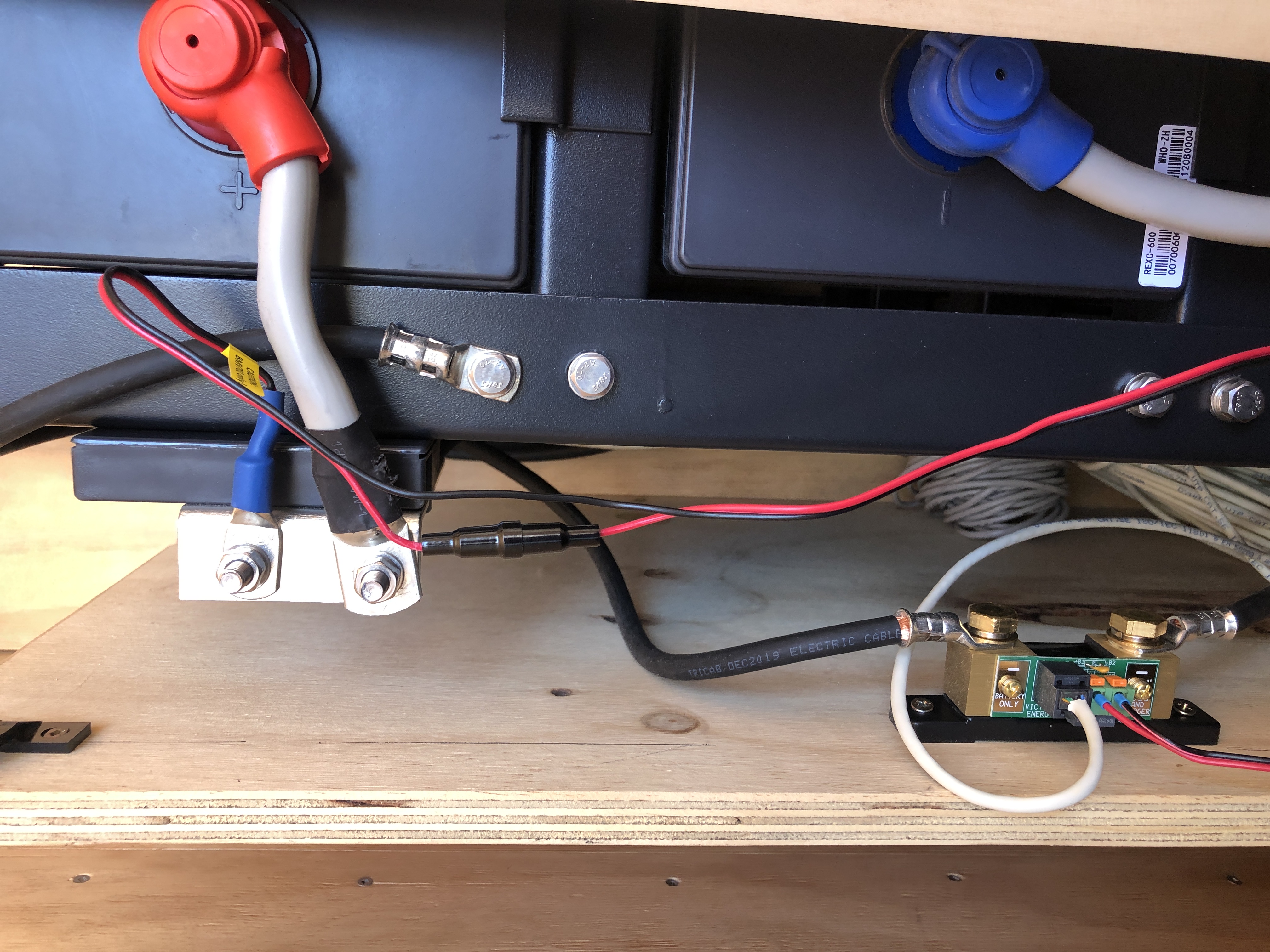
This look like a self-made cable or it is the original cable but damaged - check this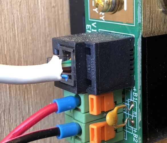
Can you check where this cables are going? If this is really the same wire it makes no sense at all.
If I see it correctly there are some (all) loads/charger directly connected to the battery.
"The electrician said the wiring he did was correct %100"
For me it looks like 0%.
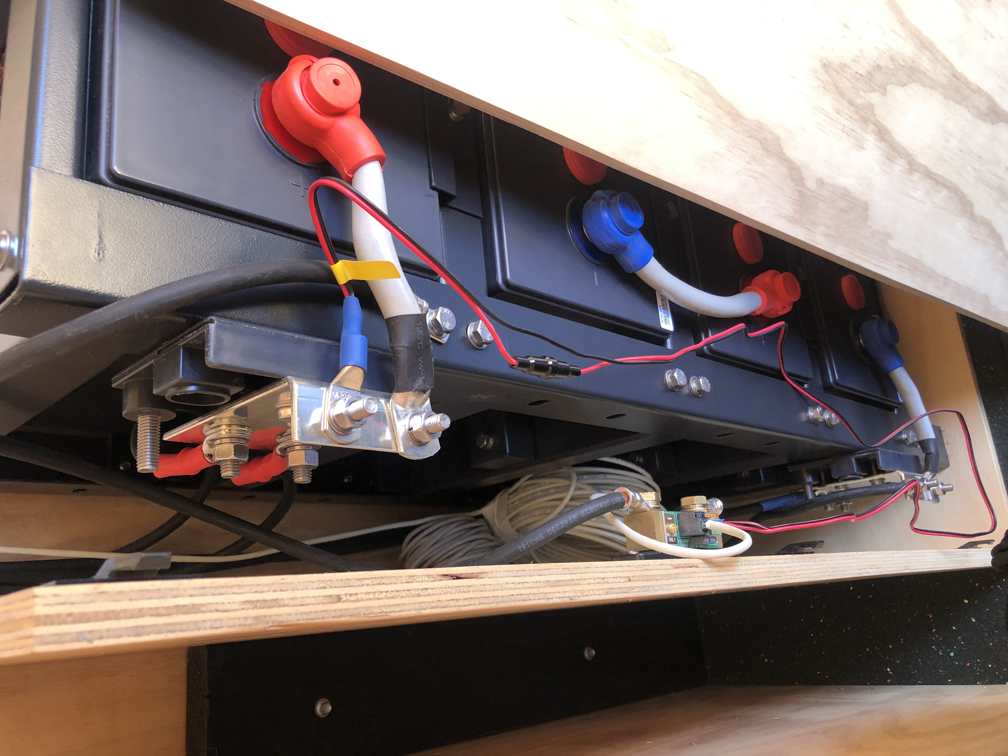
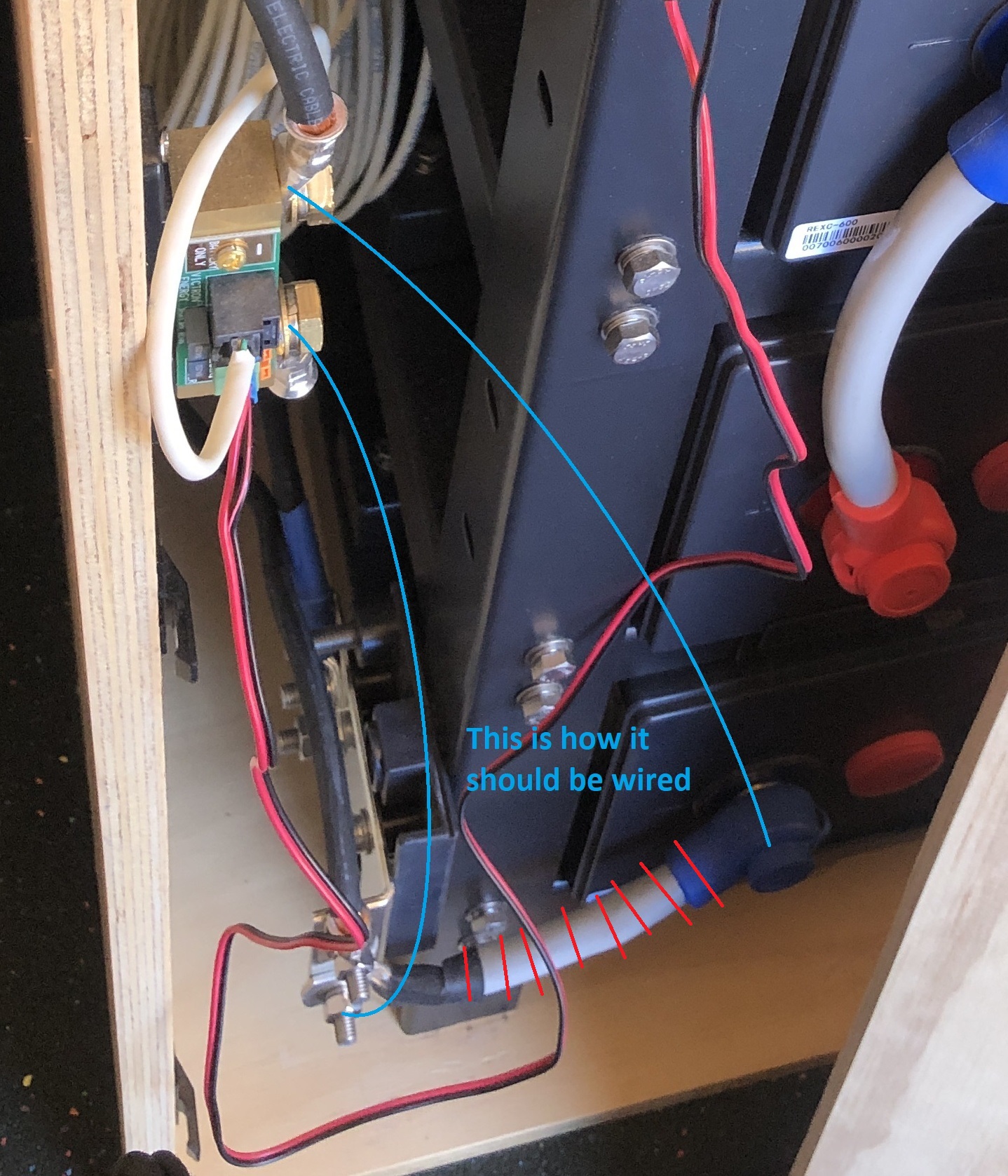
As we already thought the wiring is completely useless. There is no current flow through the shunt.
You can fix it by your self easily but the cross-section of the wire would be to small if you run your 2x 5kVA Inverters at full load for a longer time.

The wire is now 35mm² and you should increase that at least one step up to 50mm² or 70mm². At the same time you can place the shunt further down so you could use shorter wires.
And, back to that cut blue wire on the control cable....As Matthias said, is that a home-made cable? I think you might be better off getting another electrician on this if you’re not comfortable doing it yourself. Hard to tell from the pictures, but I agree that the wiring is not correct.
Thank you so much, I will give this a go today!
One Inverter is currently a spare, I do intend to add more panels at a later time.
So upgrading these wires as you say to 50mm or 70mm, should have been done during the initial install, thank you for pointing that out.
"The wire is now 35mm² and you should increase that at least one step up to 50mm² or 70mm². At the same time you can place the shunt further down so you could use shorter wires."
I am confused though about removing the main wire for the bottom battery to the terminal, is that because we are now using a wire going from the battery through the shunt?
Thank you for your patience and understanding, it's a tricky subject this solar stuff for most of us.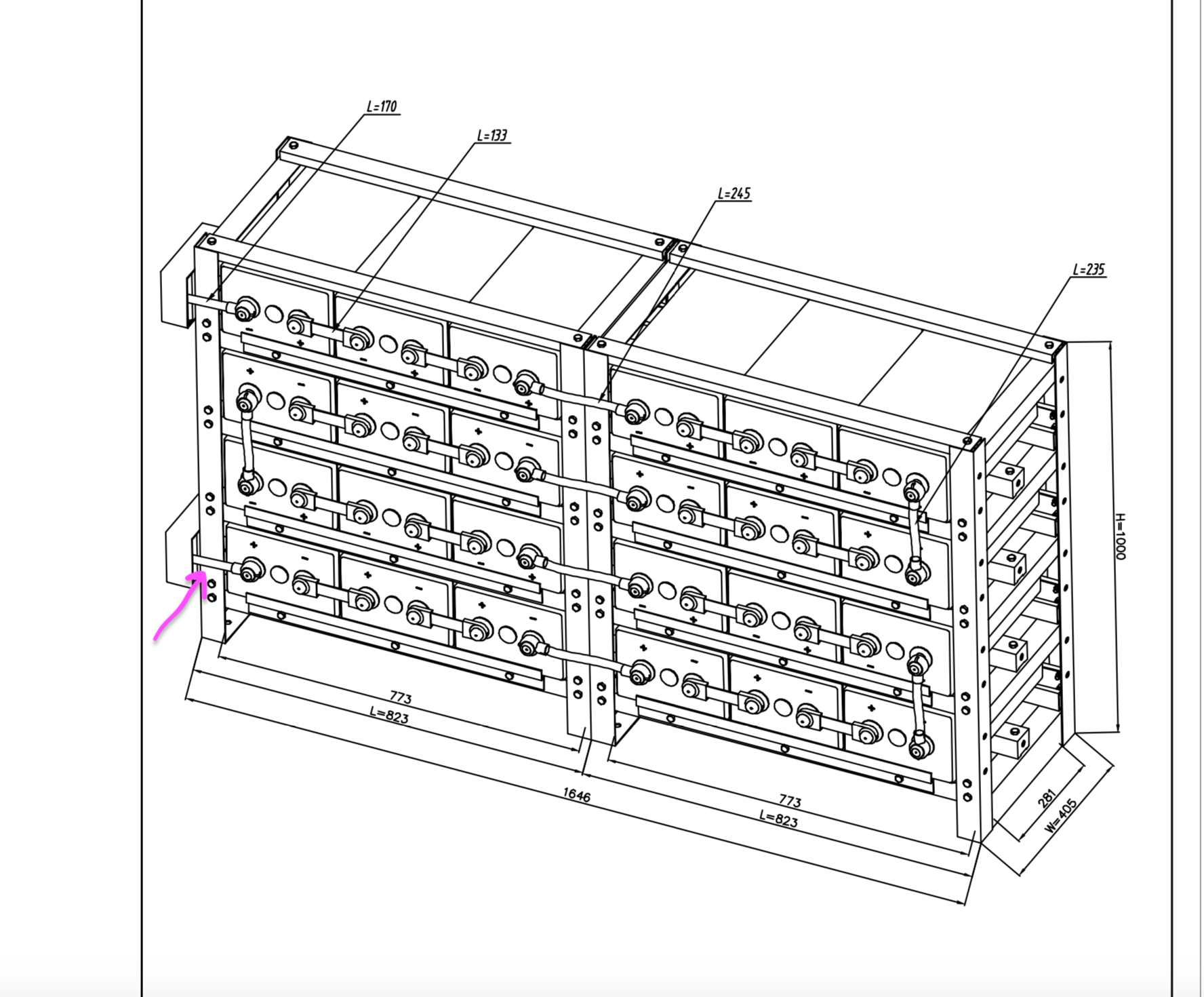
All the current coming out or going into the battery have to go through the shunt.
Shut down/switch off all load and charging sources before you disconnect that "main negative wire"!
Just checking this photo gets through before I try and write my post that I have been trying to do now for a week

OMG I have been try to respond for days now and only been getting error reports.
Thank you so much to everyone who took the time to help me @Matthias Lange - DE
I had great success and I am so happy to finally have my monitor working.
I did notice the temperature wire had caution BMV702 only, is that ok? I am using the BMV712
Hope someone can clear that up for me.
One more thing I need help with from the experts, my settings...
Please can someone help me set this up correctly for the batteries I am using, lead carbon 600ah
Thank you
Caroline