question

texascharlie avatar image
texascharlie asked

Should WFCO DC converter remain connected or be disabled?

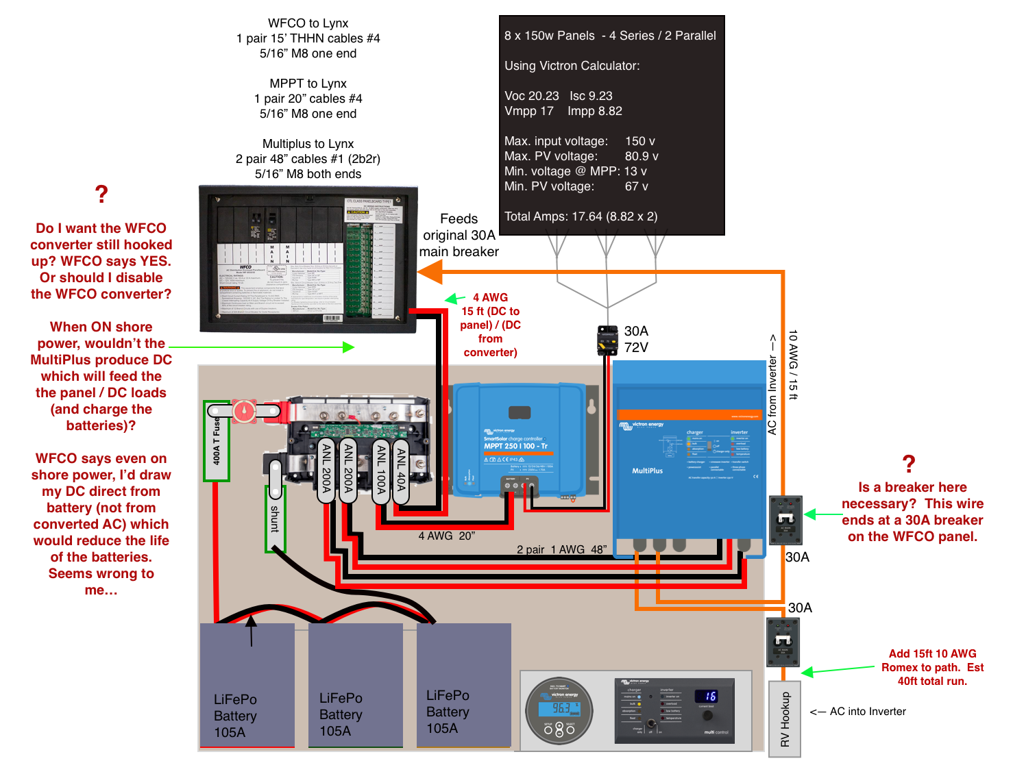
I had a confusing call with WFCO about connecting my solar system into their panel. This is in a Keystone 30A trailer.

WFCO tech support says I want to keep the WFCO panel converter connected to my new setup. I assumed I would not. WFCO says if I disconnect their converter then even when connected to shore power the WFCO panel would draw DC power directly from the batteries. I had assumed that when on shore power the MultiPlus would output DC which is what would power the DC at the panel.

Who's right?

Also, WFCO says I do not need a circuit breaker at the AC output of the MultiPlus (see diagram) because he thinks the MultiPlus has it's own circuit breaker that will protect the AC romex feeding the panel. Others have said I do need a separate breaker.

Again, who's right? Thanks for any help / feedback.


Multiplus-IIdc system
power-layout-v6.png (558.9 KiB)
2 |3000

Up to 8 attachments (including images) can be used with a maximum of 190.8 MiB each and 286.6 MiB total.

2 Answers
Kevin Windrem avatar image
Kevin Windrem answered ·

The WFCO converter should be turned off/disabled. Otherwise, it will attempt to charge your batteries from the Multi output which comes from the batteries when shore power isn't available. This will eventually drain your batteries as there's loss in every step in the loop.

I wouldn't worry about leakage current when the converter isn't receiving AC power since this is the state of the system prior to adding the inverter.

WFCO may not be aware that the Multi includes a battery charger. When on shore power, the Multi WILL keep the batteries charged and supply power to your DC loads assuming the total is less than the Multi's charger output.

You don't need a breaker on the output of the Multi. In assist mode, the Multi could produce more than 30 amps on the AC output but the AC distribution panel is breaker at 30 amps so you are safe with 10 AWG wire from the Multi to the WFCO panel.

Solid wire (romex) wouldn't be the best connection to the Multi's AC ins and outs. Space is limited in which to bend/route the 10 AWG wire. Consider stranded wire. Stranded THHN in conduit would be OK. SOOW (rubber covered) would be better because it is so much more flexible.

Keep the negative lead between batteries and shunt as short as possible.

Battery cables to shunt and main fuse should be 4/0 unless high temperature wire is used. 2/0 would be a minimum in that case.

2 comments
2 |3000

Up to 8 attachments (including images) can be used with a maximum of 190.8 MiB each and 286.6 MiB total.

texascharlie avatar image texascharlie commented ·

Thanks for the detailed reply Kevin! Very helpful.

A few follow ups...

-- "You don't need a breaker on the output of the Multi ... the AC distribution panel is breaker at 30 amps so you are safe with 10 AWG wire from the Multi to the WFCO panel."

I like that answer but just want to be double sure that I'm safe.

Since the 30A breaker is at the end of a 15ft run of 10 gauge romex, I would not want the romex to ever overheat before the breaker at the end of it trips. Is it safe to assume that the breaker would trip quickly enough?

--- "I wouldn't worry about leakage current when the converter isn't receiving AC power since this is the state of the system prior to adding the inverter."

I'm not sure I understand how to apply this to my situation. Could you expand on it? I have read stern recommendations that one (or multiple) residual-current devices (RCDs, RCCBs or GFCIs) should be used. I have a GFCI receptacle in the bathroom and near the kitchen sink. Does that qualify?

--- "Solid wire (romex) wouldn't be the best connection to the Multi's AC ins and outs..."

Since I've already got the romex, I figure I'll go ahead and use it. It will need three 90 degree bends to route it into/out of the Multiplus and no serious bend the rest of the way to the WFCO. If there's a danger involved, I can go with stranded instead, but at this point I don't see cable flexibility as an issue.

--- "Keep the negative lead between batteries and shunt as short as possible."

The lead from the battery negative to shunt is 48" long. I'd like it to be shorter but the bends required to get such thick cable from (-) on battery to the shunt requires about 44 to 48 inches.

All cables that touch battery terminals are 4/0 "extreme" battery cable rated to 105C. Pretty flexible relative to their thickness, but not super flexible.


I have another question I'll post as a new thread and I'll tag you there as well - would like your input.

0 Likes 0 ·
Kevin Windrem avatar image Kevin Windrem texascharlie commented ·

The 30 A breaker in the WFCO panel will protect the wire from over current as well as one placed at the output of the Multi. In fact, it's a series connection so anywhere in the run provides the same protection. What's not protected is a short in that line on the way to the WFCO panel. But the Multi inverter is current limited as is the input to the Multi. So you are safe.

The WFCO converter can be disabled by disconnecting its AC input. The converter's DC output is still connected to the DC bus but should not cause a problem. With the AC disconnected, the converter's leakage current would be the same as an unmodified system running without shore power. If you feel more comfortable, you can also disconnect the DC output of the converter.

Typical RV wiring routes all outlets through one or more GFCIs. One is normally found in the bathroom. This protects all user outlets. Receptacles for microwave and refrigerator are not normally protected by a GFCI but this is not required since the user doesn't have access to them in normal use.

I don't think there is danger in using 10 AWG romex into the Multi, however it could put strain on the terminal blocks and circuit board. The result could be stress cracks in the soldered connections between the terminal block and the circuit board.

Any voltage drop in the lead between batteries and shunt affects the accuracy of the BMV voltage measurement when current is being drawn. Voltage drop of 0.07 volts for 300 amps, 48 inches of 4/0 probably not a factor.

0 Likes 0 ·
jaywolfe avatar image
jaywolfe answered ·

You can easily remove the charger converter from the wfco. In effect using it as a distrbution board

This is what you need to do.


If your unsure get a qualified spark to install it


2 |3000

Up to 8 attachments (including images) can be used with a maximum of 190.8 MiB each and 286.6 MiB total.

Related Resources

MultiPlus-II Product page 

MultiPlus-II Manual

MultiPlus-II 230V Datasheet 

VE.Bus Error codes

Additional resources still need to be added for this topic