question

cobraphil avatar image
cobraphil asked

Will a Multiplus-II work in this scenario? ESS with AC coupled PV, only want to power critical loads from battery

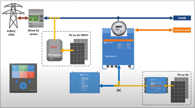
I am investigating the use of a Multiplus-II in the scenario illustrated below and have a couple of questions. The SMA inverter is already in place and I do not own it so therefore do not have the option to move it. I would be adding everything else in the schematic.

1) To power the critical loads, I want the power to come from the PV on DC array first, then the battery, then the PV on AC Array, then the grid. Is that possible?

2) To power the normal loads, I want the power to come from either of the PV arrays, then the grid, but never from the battery. Is that possible?

3) With the SMA and Victron inverters on the same circuit, will there be any issues such as anti-islanding conflicts?

4) On a very rare occasion, the SMA will push power to the grid. With the AC sensor installed, I am assuming the Victron will push zero power out as the net overall demand reaches zero. If the SMA were to continue to push out power to the grid, will there be any adverse effects to the Victron? Will it just stay at zero output without generating an error?

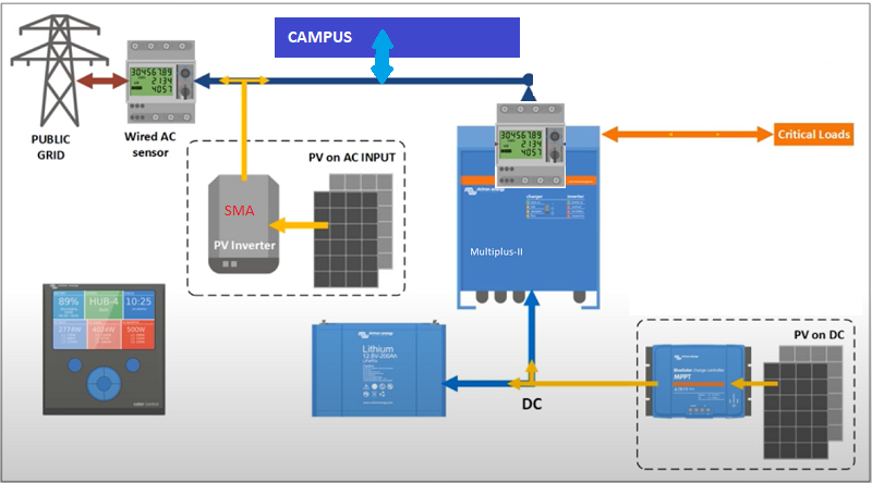
5) In a slightly different configuration, is it possible to set the ESS system to allow a certain amount of power to the grid? Say for example 2kWh?


Multiplus-II
layout.png (162.0 KiB)
2 |3000

Up to 8 attachments (including images) can be used with a maximum of 190.8 MiB each and 286.6 MiB total.

2 Answers
Rob Duthie avatar image
Rob Duthie answered ·

Hi


Yes to all those i have a system like this and it works great, no power bills for 11 months and in credit etc.


Regards

Rob D

NZ

3 comments
2 |3000

Up to 8 attachments (including images) can be used with a maximum of 190.8 MiB each and 286.6 MiB total.

cobraphil avatar image cobraphil commented ·

Thank you Rob for your response. A couple of follow-up questions.

1) In case the mains are lost, the Multiplus-II will still power the critical loads from the PV on DC array and then the battery, but will drop the normal loads. Is that correct?

2) I have been looking through the ESS configuration manual and still have a lot to learn. But where would I find the setting to disable the battery from powering the normal loads and only powering the critical loads as asked in question 2 above?

3) If I purchase the Control Control GX, do I need to purchase the GX edition of the Multiplus-II? What would be the pros and cons of doing so?

Thanks. Still trying to understand how all of the components interact.

0 Likes 0 ·
marekp avatar image marekp cobraphil commented ·

You would need only one GX device in the system.

As to which one it depends on your needs.

0 Likes 0 ·
Rob Duthie avatar image Rob Duthie cobraphil commented ·

Hi

1 Yes

2 It is all done with ESS and the loaded assistants in the inverter etc.

3 No GX version is all included in the GX Mulitplus2 so a CCGX is not required. If you are going for a plain Mulipus2 yes you will need a CCGX of raspi controller.

0 Likes 0 ·
Guy Stewart (Victron Community Manager) avatar image
Guy Stewart (Victron Community Manager) answered ·

Hi @CobraPhil,

The AC PV will power the load first, then the rest with DC PV (they will share quite well), then from the battery, then lastly from the grid.

When the MultiPlus-II is connected to the grid, the critical load circuit is connected directly to the normal AC load circuit.

If you NEVER want to power the AC load from the battery, then you would need to change the location and programming of the energy meter from a grid meter, to a PV meter, depending on your SMA that might not even be necessary to have an energy meter at all. This will preclude your DC PV from powering those loads as well before the battery is charged, only the AC will power the load when battery is not full.

If you enable export of the DC, then once the battery is full, the DC PV will then be exported to the grid AFTER it first powers the Loads on the AC input of the Multi.

Do you want the battery cycling to power the critical loads even when the grid is connected, or ONLY use the battery when the grid goes down, and then use the battery to power the critical loads?

No anti-islanding conflicts with that system design. In a grid outage, the SMA will shut down. The Multi will isolate it's AC-input, and continue to provide power to the critical loads on the AC-output.

The Victron system will try to use any available power before it is exported to the grid (either to run loads or charge the battery). If there is surplus available, even if the unit has been set to not allow export, it will try it's best to use that power to prevent export, reducing PV production where it can, but if it has no control to reduce output (such as SMA), then it will report the export without an error.

You can limit the export from the system AC and DC PV to a specific amount (such as 2 kW) with the latest firmware on all devices.

7 comments
2 |3000

Up to 8 attachments (including images) can be used with a maximum of 190.8 MiB each and 286.6 MiB total.

cobraphil avatar image cobraphil commented ·

Thank you Guy for your response. Your statement about the critical load and normal load being directly connected has me concerned about my proposed layout.

This installation is for a small college. The critical AC load is my house and the normal load is the rest of the college campus. I don't want any power from the DC array or battery being sent to the normal load circuit (campus) unless there is a surplus and the critical load (my house) has been fully met first. From your statement it does not sound like that is possible. Even with both PV arrays in place, we will still require the public grid. My desire is to first supply power to my house (no electric bill) and then charge the battery, and then send the surplus to help the campus electric bill.

And yes, I want the battery to cycle daily, supplying power to the critical load only (my house) at night time and recharging during the day.


0 Likes 0 ·
Guy Stewart (Victron Community Manager) avatar image Guy Stewart (Victron Community Manager) ♦♦ cobraphil commented ·

What you want to do IS possible.

So in the diagram that you have shown above, you would need to remove/not install the Energy Meter between the grid, campus loads and your Multi.

But it will mean the campus load is also not visible on your system, and then the multi will not try to discharge the battery to get the grid import to zero.

Critical loads connected on the output of the Multi will still be supplied by all visible solar and the battery (and lastly the grid).

If you connect the SMA AC PV communications only, it will still use that (either via Ethernet or an energy meter) when available to charge your system.

0 Likes 0 ·
cobraphil avatar image cobraphil Guy Stewart (Victron Community Manager) ♦♦ commented ·

Thanks once again Guy. I wish I could understand this better than what I am right now. Let me just restate in my own words what you are probably already saying. Notice my wording differentiating Critical Loads and Loads (maybe this is where I am getting confused).

1) Critical loads will be powered first by DC array, then by battery, then by AC input whether that be from AC array or grid.

2) Loads will be supplemented by DC array when surplus is available, but never by battery. I guess I don't see how the victron knows the difference between the DC array and the battery if they are on the same DC circuit?

3) On loss of mains, Loads will be disconnected but critical loads will remain powered as long as sufficient DC power is available.

4) In order to not us battery for loads, the AC sensor must be removed. By doing this the Victron will not have the ability to limit feedback to the grid. But this can still be accomplished by limiting the SMA.

5) By removing the AC sensor, are we not using ESS now? I thought the sensor was required for an ESS system?

6) Since the grid, AC input, and AC output to Loads are essentially the same circuit, is the AC line tied to AC-IN or AC-Out?

Sorry for so many questions. I would be willing to pay someone to make sure this design is correct if you know of anyone that does that kind of service.

I have added my power meter to the drawing below. Anything coming in from the power meter I have to pay for. This is what I am trying to limit.

0 Likes 0 ·
13127-layout.png (169.0 KiB)
Guy Stewart (Victron Community Manager) avatar image Guy Stewart (Victron Community Manager) ♦♦ cobraphil commented ·

Hi @CobraPhil,

I am working on a new ESS training right now - so your questions help us both.

It might help you to hear me describe what is going on in the basics of ESS,

Your installation is more advanced, and I will get to that too later in the training.

Intro to ESS (working draft)

Part 1

Part 2

Part 3

If you have any comments, questions or suggestions that are SPECIFIC to the info presented in those videos, I would appreciate them in the comments field on those works-in-progress videos.

0 Likes 0 ·
Guy Stewart (Victron Community Manager) avatar image Guy Stewart (Victron Community Manager) ♦♦ cobraphil commented ·

Hi @CobraPhil,

I would ALWAYS recommend contacting your local Victron specialists to find one you like and who is experienced with what you are trying to do - https://www.victronenergy.com/where-to-buy

1) Critical loads will be powered first by DC array, then by battery, then by AC input whether that be from AC array or grid.

That is 100% correct.

2) Loads will be supplemented by DC array when surplus is available, but never by battery. I guess I don't see how the victron knows the difference between the DC array and the battery if they are on the same DC circuit?

Non-critical Loads will only be supplied by DC solar that is allowed to export. The battery will be charged BEFORE the DC solar exports and supplies the loads. The DC MPPT array is connected to the GX device, and communicating its production. The GX device is co-ordinating the show, so knows how much solar is being produced and from where, and where it should be directed.

3) On loss of mains, Loads will be disconnected but critical loads will remain powered as long as sufficient DC power is available.

Correct.

4) In order to not use battery for loads, the AC sensor must be removed. By doing this the Victron will not have the ability to limit feedback to the grid. But this can still be accomplished by limiting the SMA.

Sort of, you can still limit the export of DC solar from the Victron system, but you will not know if that 'limited' solar will be going to non-critical loads, or exported out to the grid. Yes, though how that SMA works with export limiting is outside of Victron's control.

5) By removing the AC sensor, are we not using ESS now? I thought the sensor was required for an ESS system?

AC sensor is not required for an ESS system. It is only required if you want to add an element that isn't on the output side of the Multi, or not connected by some other comms to the GX device.

6) Since the grid, AC input, and AC output to Loads are essentially the same circuit, is the AC line tied to AC-IN or AC-Out?

There is an internal relay inside the MultiPlus, when the grid is available, the Multi will sync to it and then the relay closes and AC-In is connected to AC-Out (and the grid sets the AC voltage and frequency). You must NEVER connect the grid or any other AC supply to AC-Out yourself, that is for the Multi to control.

0 Likes 0 ·
cobraphil avatar image cobraphil Guy Stewart (Victron Community Manager) ♦♦ commented ·

Ok, the picture is becoming clearer in my head. Thank you for the detailed answers. I still need to solve one issue. Basically, I have two export points. One, to the rest of the campus, which I want to export as much DC PV Power as I can. And two, to the grid, which I don't want to export at all. Would it be possible to install two energy meters (notice meter at the grid and a meter at the Victron), or a Raspberry pi with Modbus communications and Node-Red in such a way that whenever I am exporting to the grid, I can in real-time decrease that amount of power from being exported from the Victron? So the campus is receiving just enough power (without using battery) to produce a net-zero at the grid? The only connections would be AC-IN and Critical Loads. No connection on Loads. The campus would be considered the grid as far as the Victron is concerned. So if there is a 200Wh reading at the grid, the Victron would need to decrease it's output by that amount, but still maybe putting out 1000Wh and it would be doing this in realtime.

Also, is the Mutliplus II 5k registered for use in Papua New Guinea?

Thanks.

0 Likes 0 ·
layout.png (165.1 KiB)
cobraphil avatar image cobraphil Guy Stewart (Victron Community Manager) ♦♦ commented ·

Ok, the picture is becoming clearer in my head. Thank you for the detailed answers. I still need to solve one issue. Basically, I have two export points. One, to the rest of the campus, which I want to export as much DC PV Power as I can. And two, to the grid, which I don't want to export at all. Would it be possible to install two energy meters (notice meter at the grid and a meter at the Victron), or a Raspberry pi with Modbus communications and Node-Red in such a way that whenever I am exporting to the grid, I can in real-time decrease that amount of power from being exported from the Victron? So the campus is receiving just enough power (without using battery) to produce a net-zero at the grid? The only connections would be AC-IN and Critical Loads. No connection on Loads. The campus would be considered the grid as far as the Victron is concerned. So if there is a 200W reading at the grid, the Victron would need to decrease it's output by that amount, but still maybe putting out 1000W and it would be doing this in realtime. The key here is to not use the battery for anything except the critical loads because the campus will drain the batteries in no time.

Also, is the Mutliplus II 5k registered for use in Papua New Guinea?

Thanks.

0 Likes 0 ·