question

rjoustra avatar image
rjoustra asked

System overview

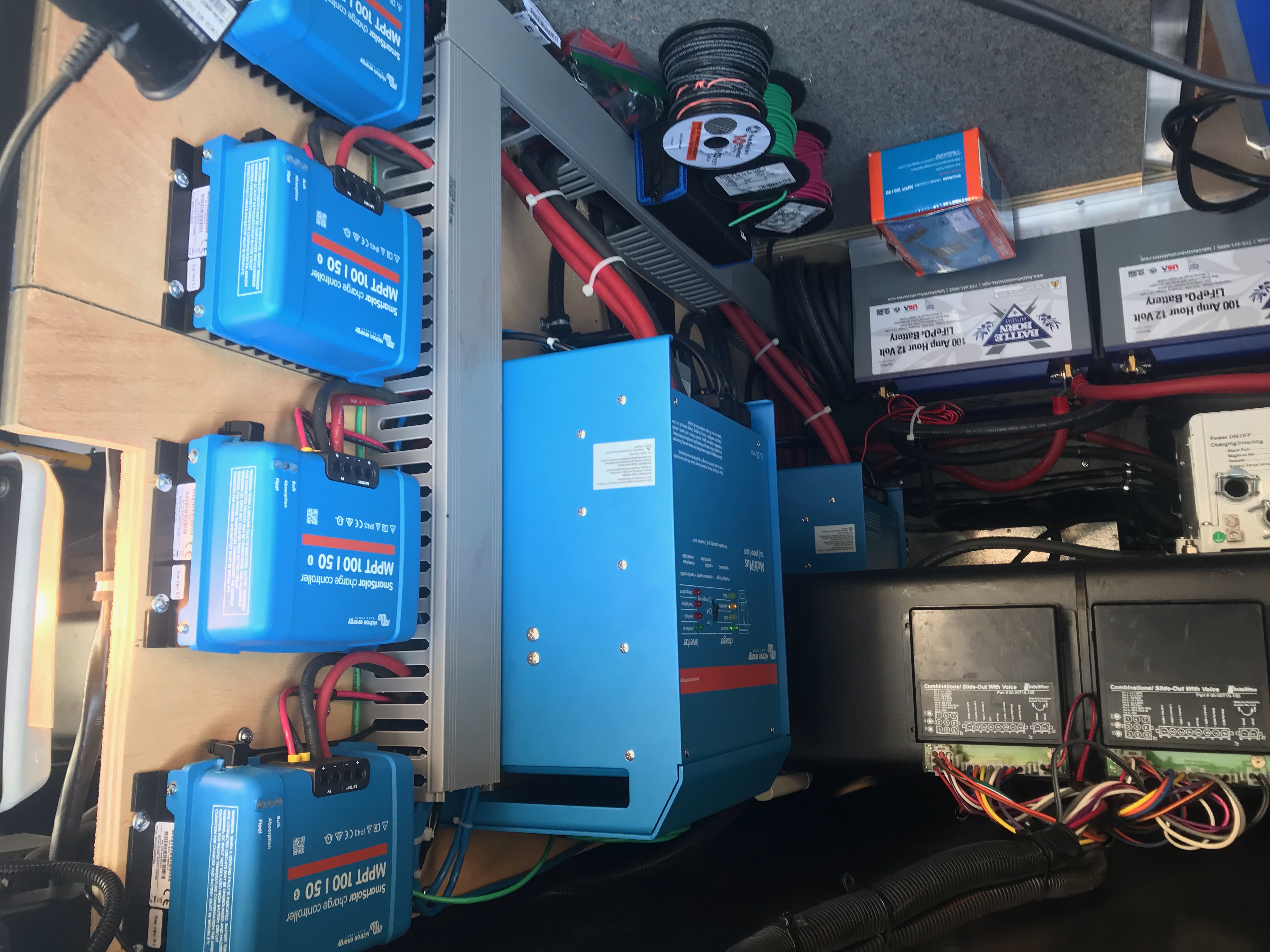
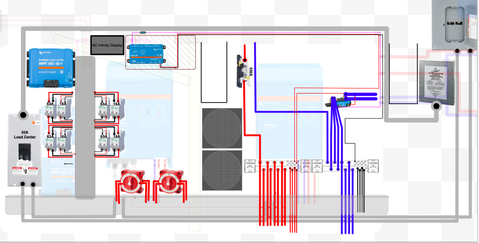
I would like to put this out to the community to see if I am missing anything in the way I currently have my system wired before I power everything up


12VDC side

Batteries

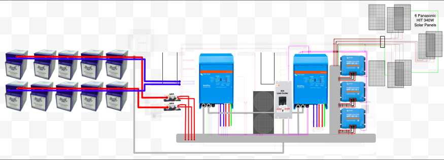
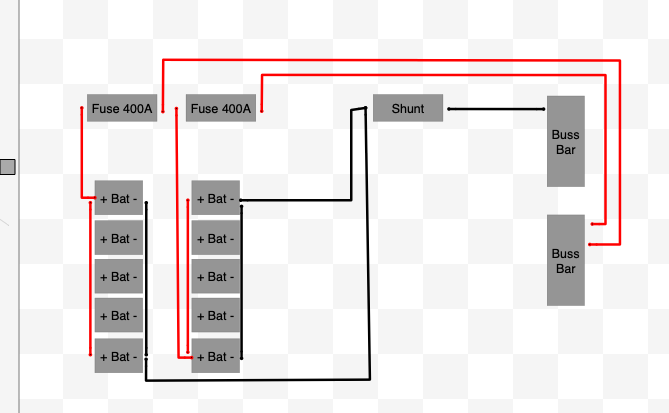
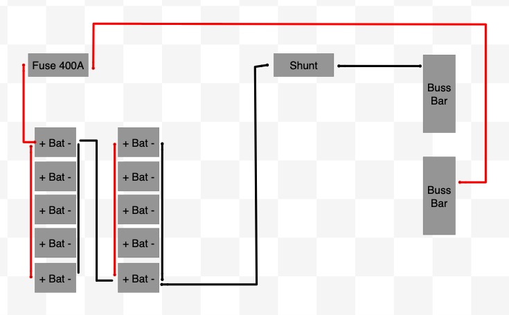
I have 10 battleborn lithium batteries divided into two banks interconnected with 4/0 cables.

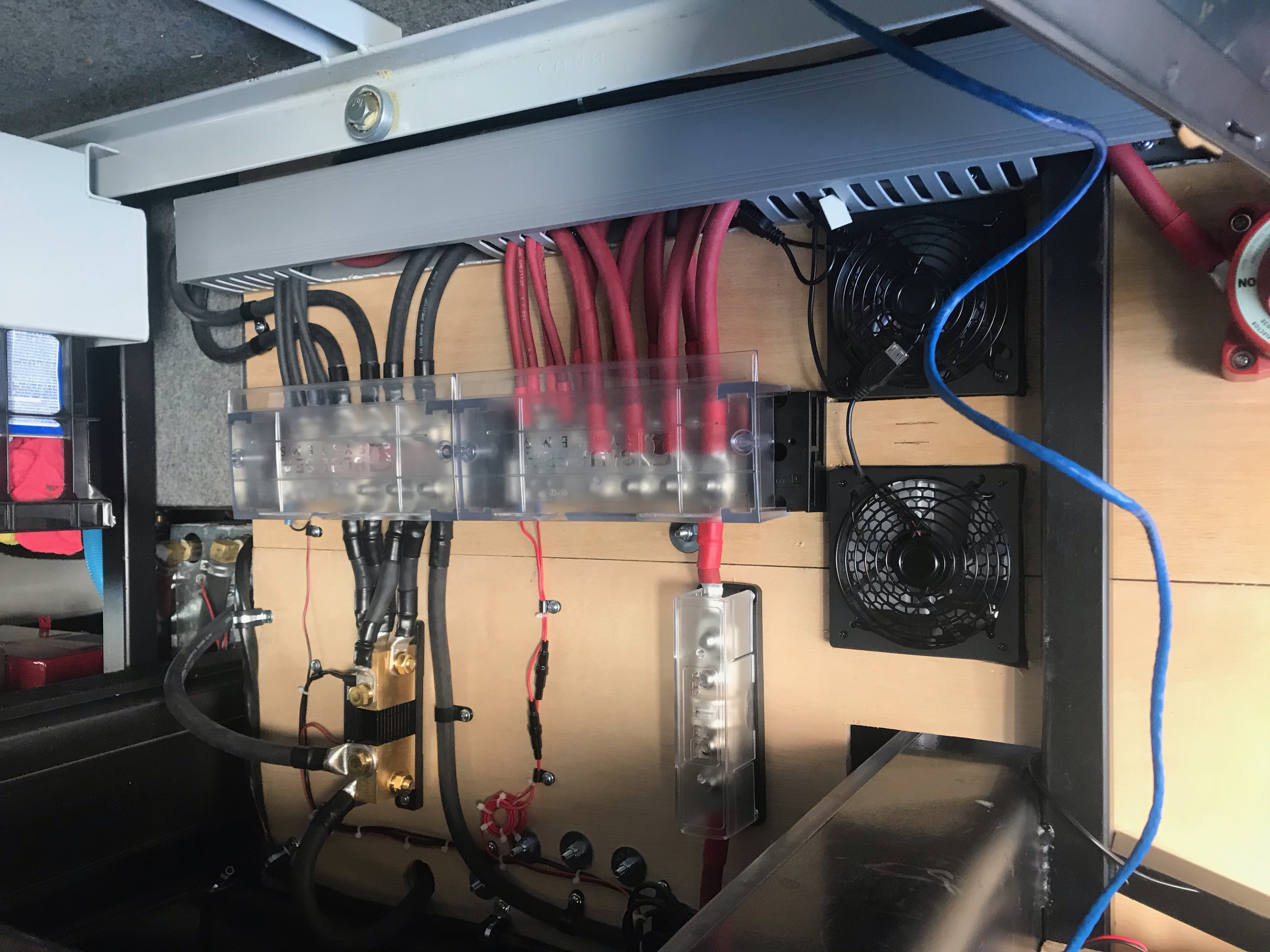
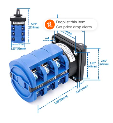
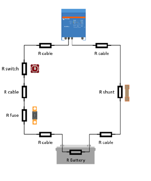
Each banks positive goes through a 400 amp class t fuse then through a battery disconnect and over to a 1000 amp buss bar.

Each negative goes through a smart shunt and then to a 1000 amp buss bar.

Cables are within inches of being the same length slight variance due to placement of switches

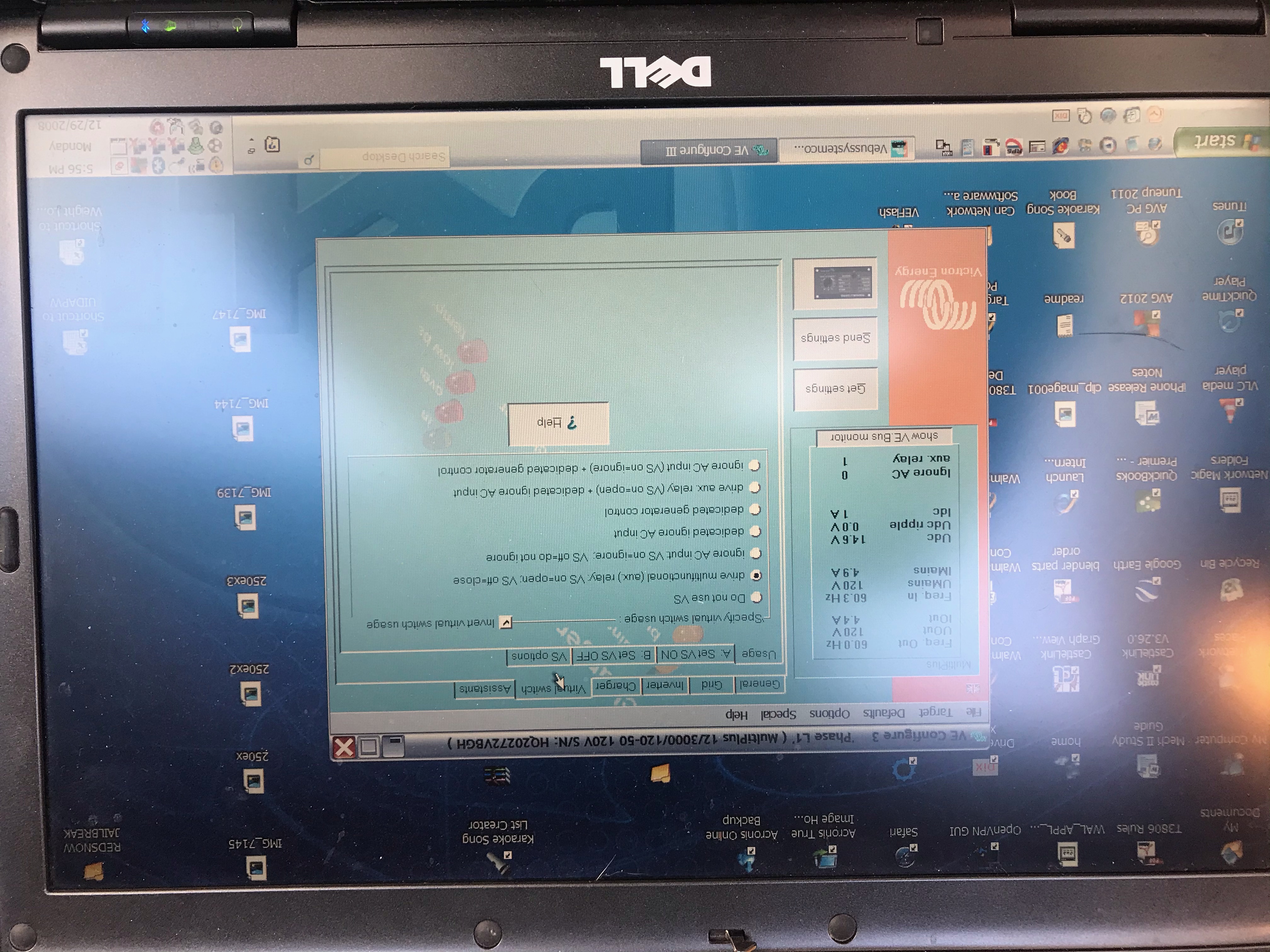
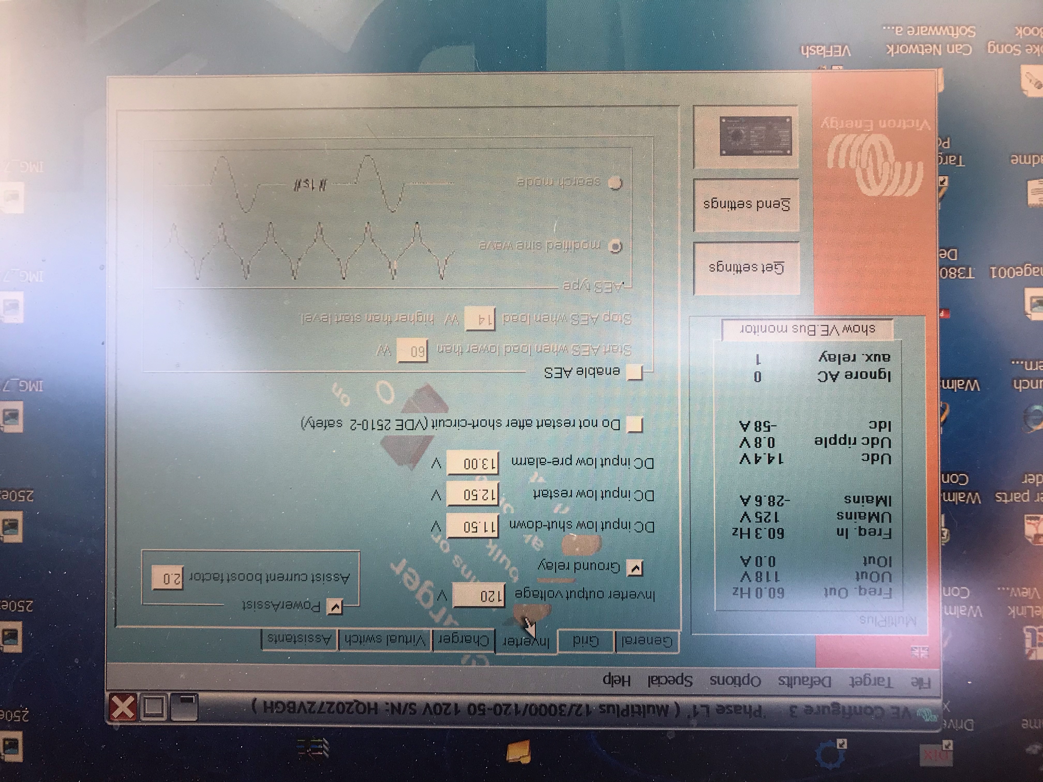
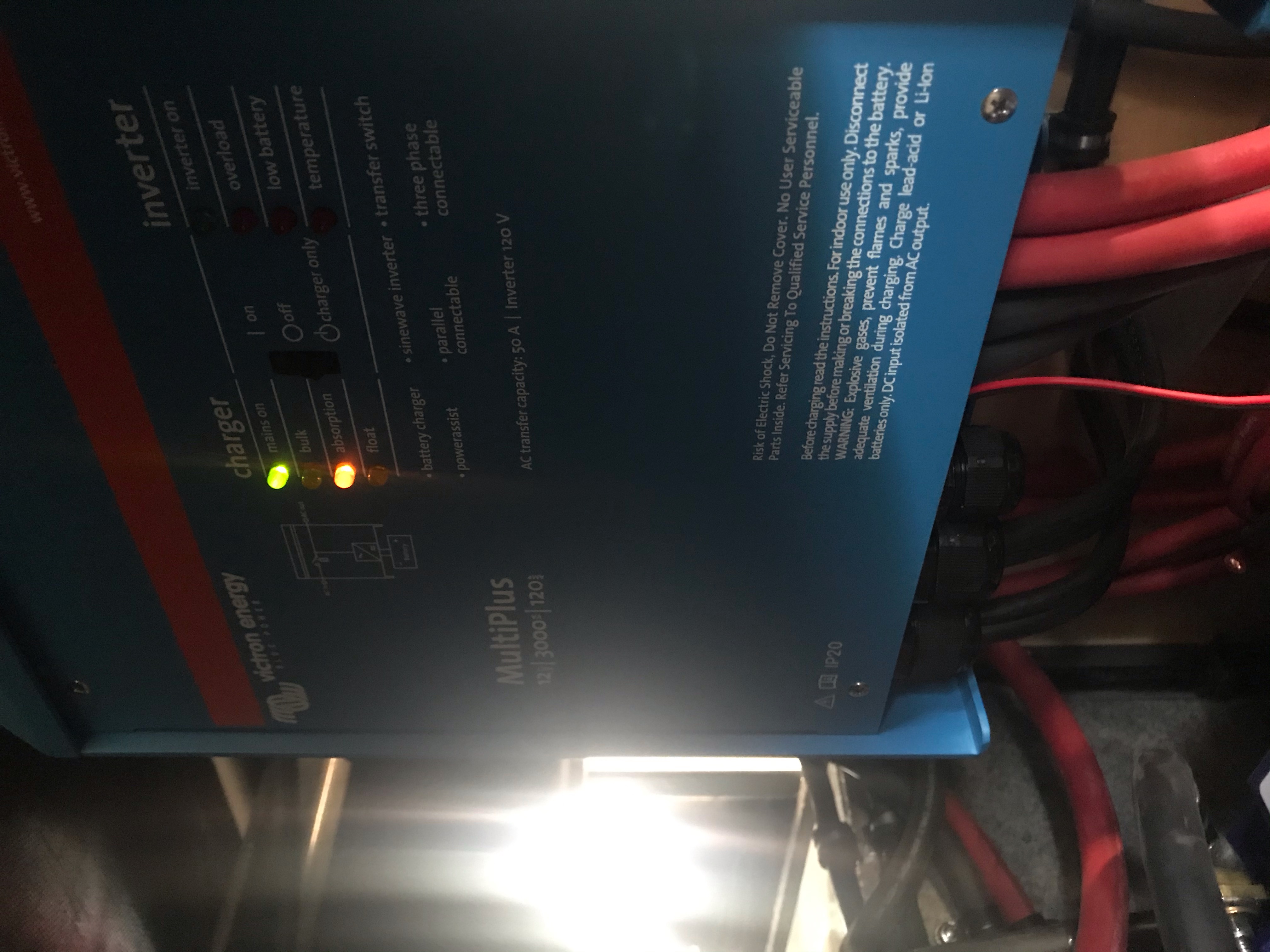
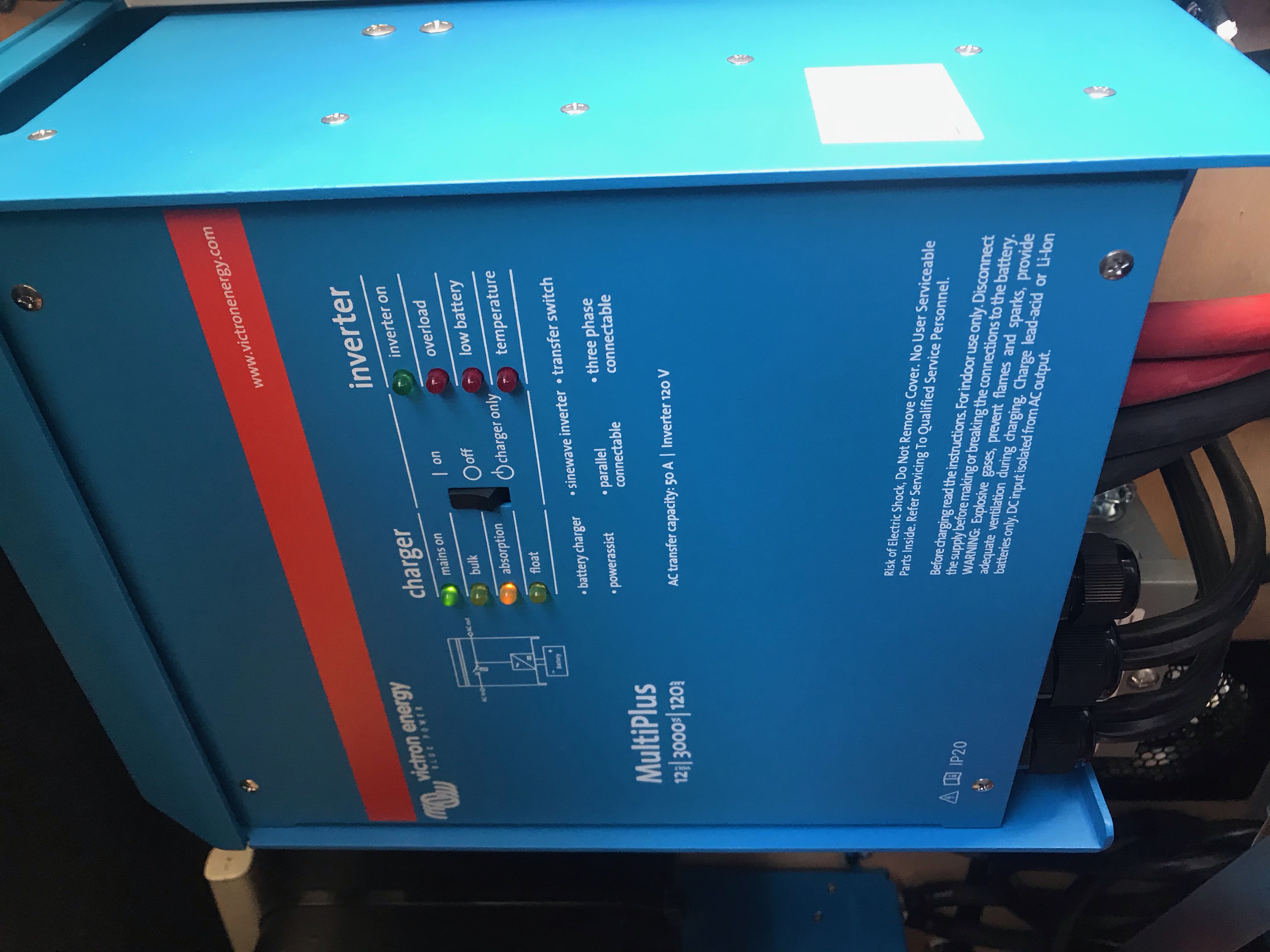
Inverters 2 Multiplus 120v 3000

Each inverter positive and negative go directly to the the buss bars using two 2/0 for both pos and neg

Each inverter casing is grounded to the motorhome chassis local to the inverters

Cables are the same length

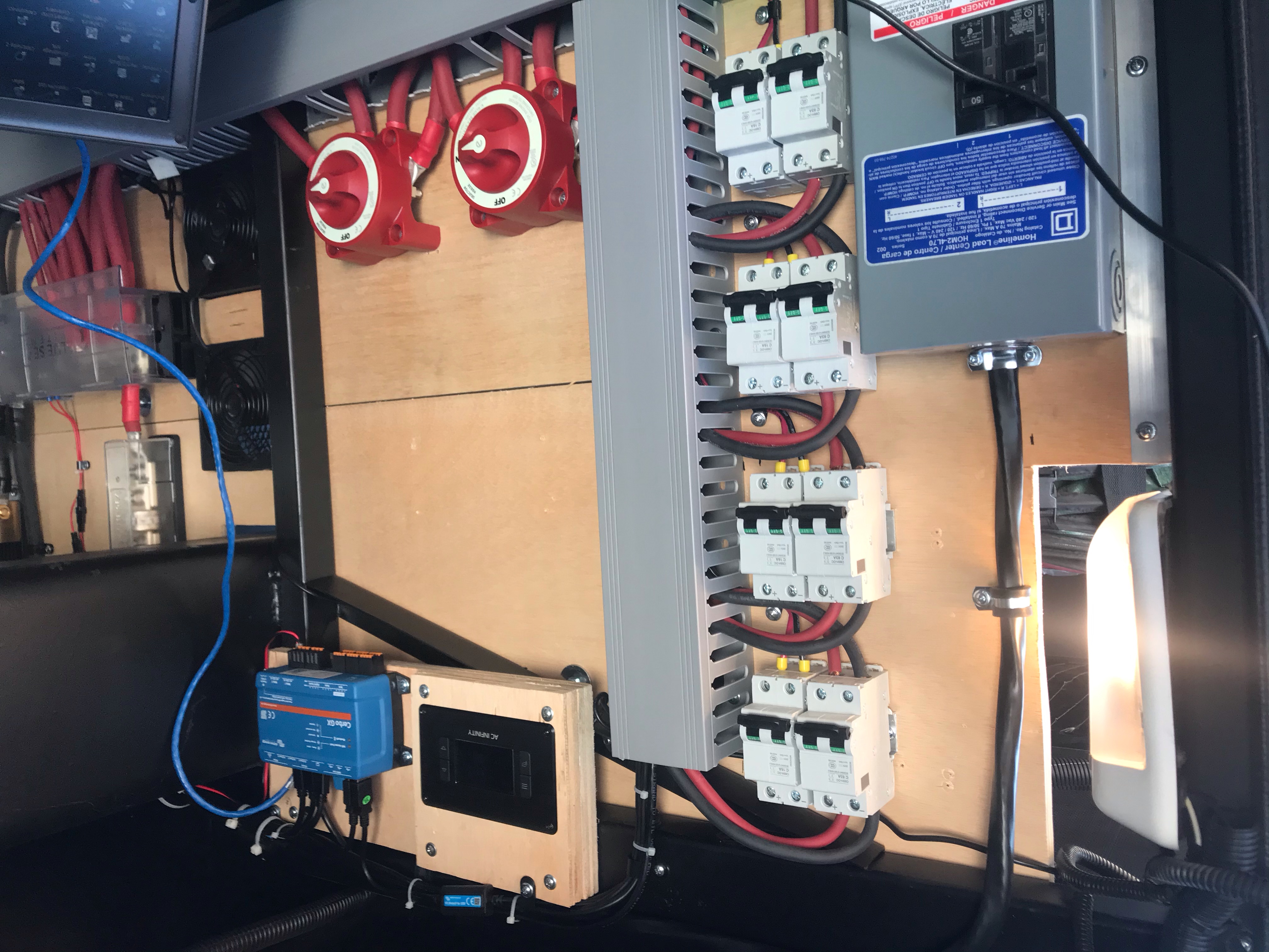
Charge controllers 100/50 x 4

Each pair of solar panels go through din rail pos & neg breakers to the PV input on the controllers over 10awg wire. The wire calculator I used was border line 10 or 12 so I went 10

Each output of the controllers battery side goes through a din rail pos & neg breakers then on to the buss bars over 6 awg wire

Charge controller chassis grounds are daisy chained and terminate on the motorhome chassis at the same point as the inverters

Cables are the same length.

Motorhome DC distribution

I am using the existing motorhome 3/0 inverter cables to supply voltage back to the original battery compartment where the original chassis ground is, dc distribution and alternator cables go to.
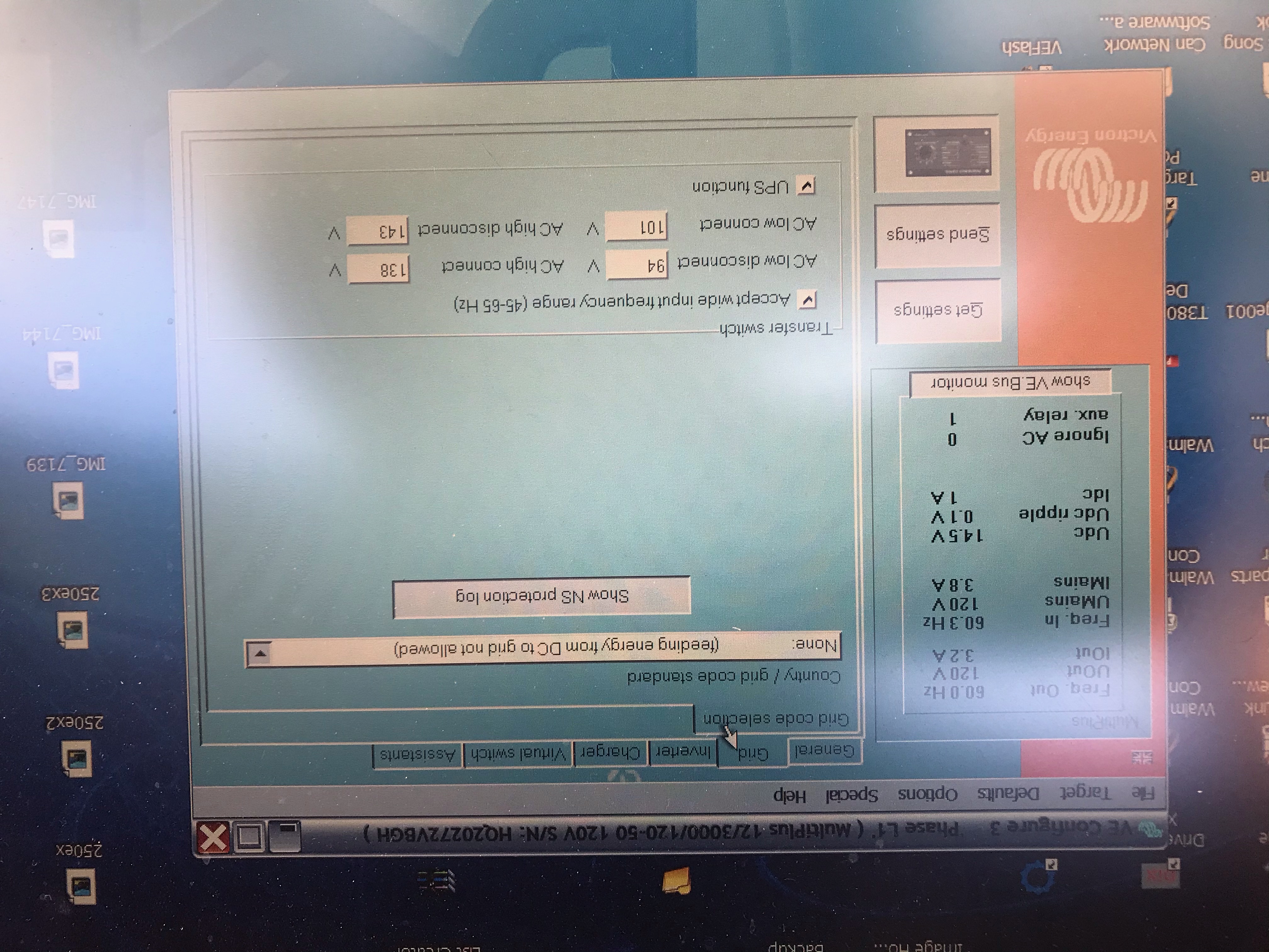
AC 120v 50amp

AC comes in from either shore power or the generator through the transfer switch over to a double pole 50 amp breaker then the ac is split into two circuits 1 going to each inverter.

AC1 out on each inverter is fed to another 50 amp double pole breaker and then continues to the main AC distribution panel for the motorhome each inverter feeding one leg of that distribution panel

AC cabling is within a couple feet of being the same length. Not sure how critical the symmetry is when running separate legs of the ac panel since the inverters will not share each other’s load.


Is there anything I am missing here?

Thanks Richard


solar
2 |3000

Up to 8 attachments (including images) can be used with a maximum of 190.8 MiB each and 286.6 MiB total.

4 Answers
Kevin Windrem avatar image
Kevin Windrem answered ·

Awesome system you are putting together.

There's a multi-phase tutorial on professional.victronenergy.com/online-training you should watch, or have someone trained in complex systems do the final checkout and configuration.

You didn't mention control. Do you have a GX device (CCGX, Cerbo GX, etc)? If so, everything should be connected to this via appropriate cables (VE.Bus for the inverters, VE.Direct for the charge controllers and shunt)to . A GX device provides extremely helpful if not essential central control.

Use care in connecting an alternator directly to your DC bus. I'm not an expert on this but those that are recommend a DC-DC charge controller to avoid overcharging your batteries and/or destroying the alternator.

I don't think the system will properly manage separate shunts. The two battery bank negative leads should be connected to the battery side of the same shunt.

It's critical that the negative leads to all inverters are connected together BEFORE the VE.Bus cables are connected but sounds like you've done that.

Victron recommends a common battery bank for all inverters in the same system. That says, you should be connecting both battery banks to the same busbar. I can't tell for sure if that's what you are doing. If not, consider rewiring it for a common positive busbar.

All inverter/chargers in the system MUST be connected together via VE.Bus cables. This is needed

Before connecting any AC power or loads, it is essential to set up the system for split-phase operation. You will need to use VE.Bus System Configurator tool via a MK3 USB to VE.Bus adapter. You can not use VictronConnect for systems with more than one inverter.

RV power sources vary: Split phase 120/240 50 amp is common for larger RVs. It sounds like you are in this category. But even with that setup, you may encounter 120/208 50 amp (2 legs of 3-phase) and even a single 120 volt 30 or 20 amp receptacle. In order to handle these configurations, make sure you select L2 floating phase in VE.Bus System Configurator.


76 comments
2 |3000

Up to 8 attachments (including images) can be used with a maximum of 190.8 MiB each and 286.6 MiB total.

rjoustra avatar image rjoustra commented ·

Thank you for the input.

Yes I have a cerbo gx connected to everything. (Sorry missed stating this)

Yes the 2 banks are connected to the one 1000 amp smart shunt

Yes everything is landed on the same bus bars.

I have purchase a Precision Circuits LIBIM 225 to mitigate burning up the alternator. It only allows charging of the lithium bank in 15 min increments and give it a break for I believe 20 min, and cycles like this the entire time.

Question?? I thought I would be able to use the cerbo to do any configuration changes once it is setup on the network and I am local on the same network.

Yes it is a large 45' Motorhome with a 50 amp split phase panel but only 1 item in the coach actually uses split phase. I figured I could toggle it back and forth between parallel and split phase but my intent was to run them in parallel so that if I am hooked up to 30amp 120v of the same phase being sent to both inverters they would both function normally. And if they are receiving two different phases I could toggle them fairly easily to split phase if I need to. I have heard that with them in split phase when connected to the same phase one will be inverting the entire time.

Question?? Grounding? The old house batteries are grounded to the chassis which once I use the old inverter wires running to the old lead acid battery location this will ground my lithium banks to the chassis as well as connect them to the DC distribution and alternator. My Inverter cases, my charge controller cases and my solar panel frames are landed on the chassis in a different location than the battery neg bus bar will be grounded too about 10 feet from the lithium bank. Is this going to cause an issue?

0 Likes 0 ·
Joshua Warren avatar image Joshua Warren rjoustra commented ·

A cautionary note about putting Multis in parallel (same phase input) and supplying independent circuits or bus bars. In parallel operation, the Multis expect their output line conductors to be bonded together downstream; i.e., they have continuity. If you have power assist enabled in such a scenario, then when the load exceeds the input current limit, both inverters will briefly step up their voltage to overcome the instantaneous demand. But if their outputs are supplying separate circuits or bus bars that do not have continuity, what will happen when the load exceeds the input current limit is that the circuit or bus bar without the increased demand (imagine an air conditioner overcoming its locked-rotor amperage) will actually experience an overvoltage fault and the inverter on that phase will likely shut off completely.

0 Likes 0 ·
rjoustra avatar image rjoustra commented ·

One other Question?

Is there a power up sequence?

Turn on the DC First or AC First.

I would connect loads last when powering up and first when powering down.\

Thanks Again

0 Likes 0 ·
Kevin Windrem avatar image Kevin Windrem rjoustra commented ·

Cerbo can't do any inverter, MPPT or shunt configuration. Some is possible through VictronConnect but not a system with multiple inverters. You need the Windows tool set for this, and will need the MK3 to connect your laptop to VE.Bus.

The wiring for true parallel and split-phase configuration is totally different. This is not something you want to deal with every time you park your RV. The multi-inverter configuration tool provides a selection so that the phase of L2 floats relative to L1. This should accommodate any shore power you will encounter: 120/240 (legs 180 degrees apart), 120/208 (legs 120 or 240 degrees apart) or single 120 volt (0 degrees between the two legs).

Yes the grounding may be a problem. I would not tie the starter batteries into the house array to minimize this and also because the two battery banks will be slightly different voltage. Also make sure your interface to the alternator is isolated between alternator and house.

Again, look at all the Victron documentation and tutorials on multiple inverters. There are a lot of useful information there and it'll save you headaches later.

There are notes on the Victron site also about powering up the inverters. There is always a surge when the capacitors across the DC inputs charge whether that surge comes from the batteries or from the AC input. If the batteries are not connected, expect an AC input breaker trip the first time power is applied. The surge of DC current with discharged caps is amazing. BIG sparks. You can weld your DC switches. Plan on a soft start that applies DC voltage through a resistor to charge the caps slowly. BattleBorn has a unit that handles the soft start also.

0 Likes 0 ·
rjoustra avatar image rjoustra Kevin Windrem commented ·

Battle born indicated I did not need the soft starts. Would the best bet be to charge the capacitors via the AC for the first time to avoid damaging the battery disconnect switches? I can deal with having to reset the AC breaker once or twice while they charge.

Being that the lithium banks are tied to one bus bar will they not combine to establish there combined voltage. And yes the battery voltages for both the sealed lead acid and the Lithium will be at different voltages but these are only combined using the LIBIM 225 for a matter of seconds to for example start the generator or the coach in the event one is depleted and basically act as an improved bi directional relay. Battle born has indicated that the charge settings for their lithiums will be ok for the chassis batteries There have been many Motorhomes that have used them in this way and precision circuits has designed this module for this express purpose in motorhomes.

Should I be worried about the inverters charging the chassis batteries as well after the feed back battle born and precision circuits has given me on this?


Thanks Again for all your time.


0 Likes 0 ·
rjoustra avatar image rjoustra Kevin Windrem commented ·

Precision Circuits Inc

page1image148876336 page1image148854928 page1image148852896 page1image148679296

The Lithium Battery Isolation

Manager (Li-BIM) isolates the two battery systems, chassis, and coach, in a motorhome. This prevents loads in one system from discharging both. It also connects the two battery systems together during charging. Both batteries are charged if either is being charged. The coach battery is charged while driving and the chassis battery is charged while plugged into Shore Power at a campground.

Key Features:

1. 160amp & 225amp continuous models available

2. Runs cooler using less power
a. Draws no current in ON or OFF state b. Excellent for Solar Panel use

3. Microprocessor based
a. Monitors battery state over longer periods of time b.

4. Not simply voltage dependent

a. Approved for Battery Compartments
b. Ignition Proof, SAE J1171
c. Waterproof, IEC 60529, IP66 IP67, ASTM B 117 96 Hours Salt Spray

5. Charges
a. Lithium Coach Battery from Alternator
b. Lead Acid Chassis Battery from Coach Charger

6. Isolates Batteries to prevent discharging or overcharging of Batteries

7. Prevents
a. Equalization cycles from Damaging Chassis Battery

b. Annoying clicking of Isolator Relay
c. Overcharging of Coach Battery during long drives
d. Overcharging of Chassis Battery during long stays

8. Provides Emergency Start with Dash Switch. Optional power connection for existing applications, and ground connection to allow Emergency Start of either battery.

9. Weighs under 1 pound

The Li-BIM monitors the battery voltage of both the Lead Acid Chassis and Lithium Coach batteries over long periods of time. If it senses a charging voltage, it connects the two batteries together. If the charging system is drastically overburdened, the batteries will be isolated, however, if the Li-BIM sees a long term charging of both batteries it will allow the batteries to remain connected and allow the charging system to do its job. Once the batteries have charged for one hour, the Li-BIM will isolate the batteries to prevent overcharging, and will only reconnect the batteries for charging if one of the batteries drops to approximately 80% charge, and the other is being charged. This long term monitoring of the batteries prevents the annoying relay clicking that exists in simpler isolation modules today. The Li-BIM does not guarantee 100% battery charge, but prevents harmful battery charge levels.

0 Likes 0 ·
rjoustra avatar image rjoustra Kevin Windrem commented ·

Also if I have read that I can't have just one configuration that will accommodate 50 amp 180 degree out split phase and 30amp 0 degrees out without having the secondary inverting switch to inverting only because it does not recognize the fact that it is not getting that 180 out split phase leg instead getting the same leg as the primary or master inverter. Is this true or is there a setting I can use where both will work without changing profiles in the event we are at a park with only 30 amp single phase. I have watched a video of someone that does make this change when needed and it is really only a few settings and loading saved config files to make the change and since my inverters and my cerbo are totally accessible this would not be that big of a deal but way better if one setting would do both.


Really do appreciate you taking the time to answer all my newbie questions.

I am an electrician in Automation systems by trade but this is a whole different animal.

0 Likes 0 ·
Kevin Windrem avatar image Kevin Windrem rjoustra commented ·

The multi inverter tutorial doesn't go into the L2 "floating" details. In the 180, 120 and 240 selections, incoming power is rejected if the phases don't align as specified. Floating allows the phases not be locked to one of those 3. So for sure, it would accommodate split-phase and 2 legs of 3-phase.

Someone with experience with this configuration needs to confirm it would also accommodate 0 degrees between legs.

True parallel operation is a completely different configuration and requires precise matching of input and output cable lengths in order to balance currents between the units in parallel. You really are not running the two units in parallel since they'd be going to different legs in the AC distribution panel. I'm not sure what the units would do if they saw large current difference on the AC ins and outs. So you might be into large switches on the inputs and outputs to switch them from split-phase to true parallel wiring in addition to reconfiguring the units. Failure for any physical wring to track the configuration could result in damage to the inverters so this really isn't something you want to do on a daily basis.

0 Likes 0 ·
rjoustra avatar image rjoustra Kevin Windrem commented ·

I suppose if there is anyone else in the community that could answer the configuration setup so it would work seamlessly if they were receiving split sphase 180 out which would be most common or both being put on the same phase due to the use of a 50 amp to 30 amp adaptor or dog bone as it's called which bridges the single phase and sends it over both legs of the panel without sending one inverter into inverting mode all the time.


Question? Can you tell me if you believe that starting the inverters on AC versus potentially damaging my 350 amp Blue Sea battery disconnects would be the best plan?


Thanks

0 Likes 0 ·
Kevin Windrem avatar image Kevin Windrem rjoustra commented ·

I think Victron recommends powering the inverter(s) on battery first. That way they can be configured before connecting any of the AC wiring.

I built a manual soft start for my 12-volt Multi Compact. I used a 30 watt 5 ohm resistor and a small switch to charge the capacitors before closing the main DC switch. This same resistor and switch also discharges the caps after disconnecting the battery. This should work for any 12 volt setup. Charging time will vary depending on the size and number of inverters.

I think you'll be OK powering up from AC with no battery connected. But I'd power one up at a time and do as much configuration on that unit as possible.

You can run the configuration tools in demo mode and save files which you can then load into each Multi when it's first powered. Doing this all on a bench setup is much easier than after final install.

0 Likes 0 ·
Joshua Warren avatar image Joshua Warren rjoustra commented ·

I have tried every possible variant of phasing in order to get a pair of Multis to accept both 180-degree and 0-degree offset phase inputs, and have been completely unsuccessful. It is possible to get them to accept 180 and 120 degree phase offsets, but the only way to get them to accept 0 degree offset is to put them in parallel configuration. And if you do that with separate downstream bus bars and use power assist, you'll get overvoltage faults like I described in my other comment.

0 Likes 0 ·
rjoustra avatar image rjoustra commented ·

Ok so I have the system up and running albeit with a few headaches. I am looking at the cerbo GX read out and it says I am pulling 400w in DC Power Box. This increase when I am inverting and the more AC loads I run this seems to go up. I Literally have almost nothing on in the coach and what I do is all LED. And the darn Low battery warning came on and has been on. I am running 10 Battleborn 100 ah 12v batteries. Is this normal or am I leaking voltage
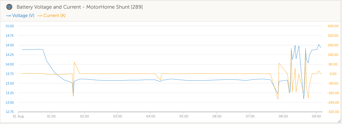
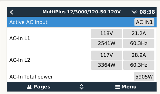
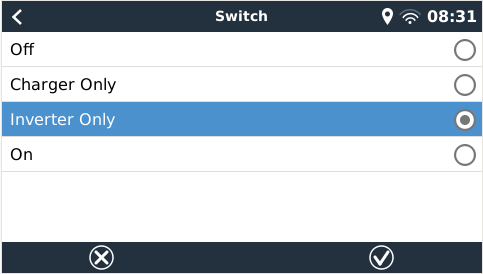
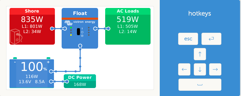
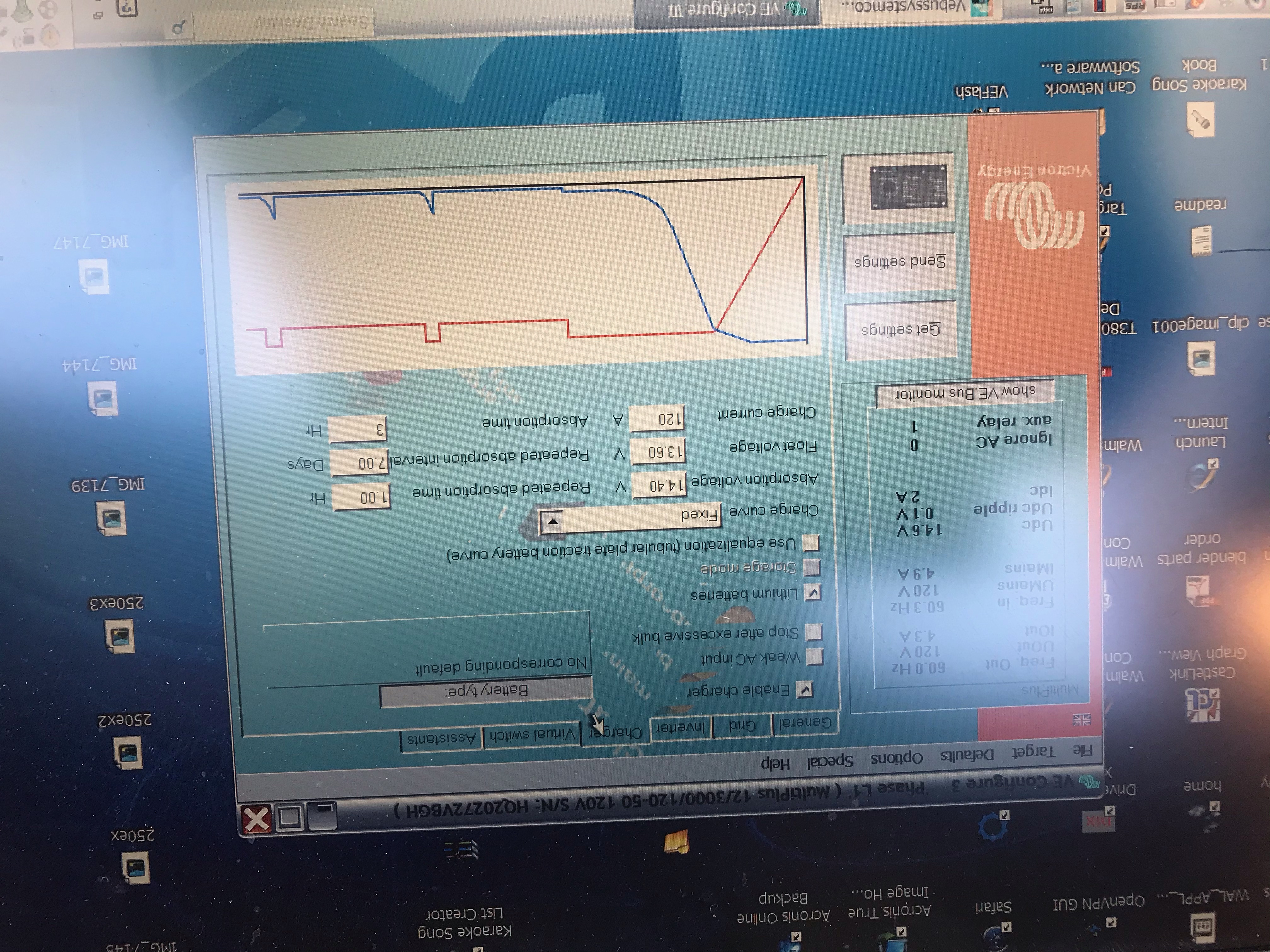
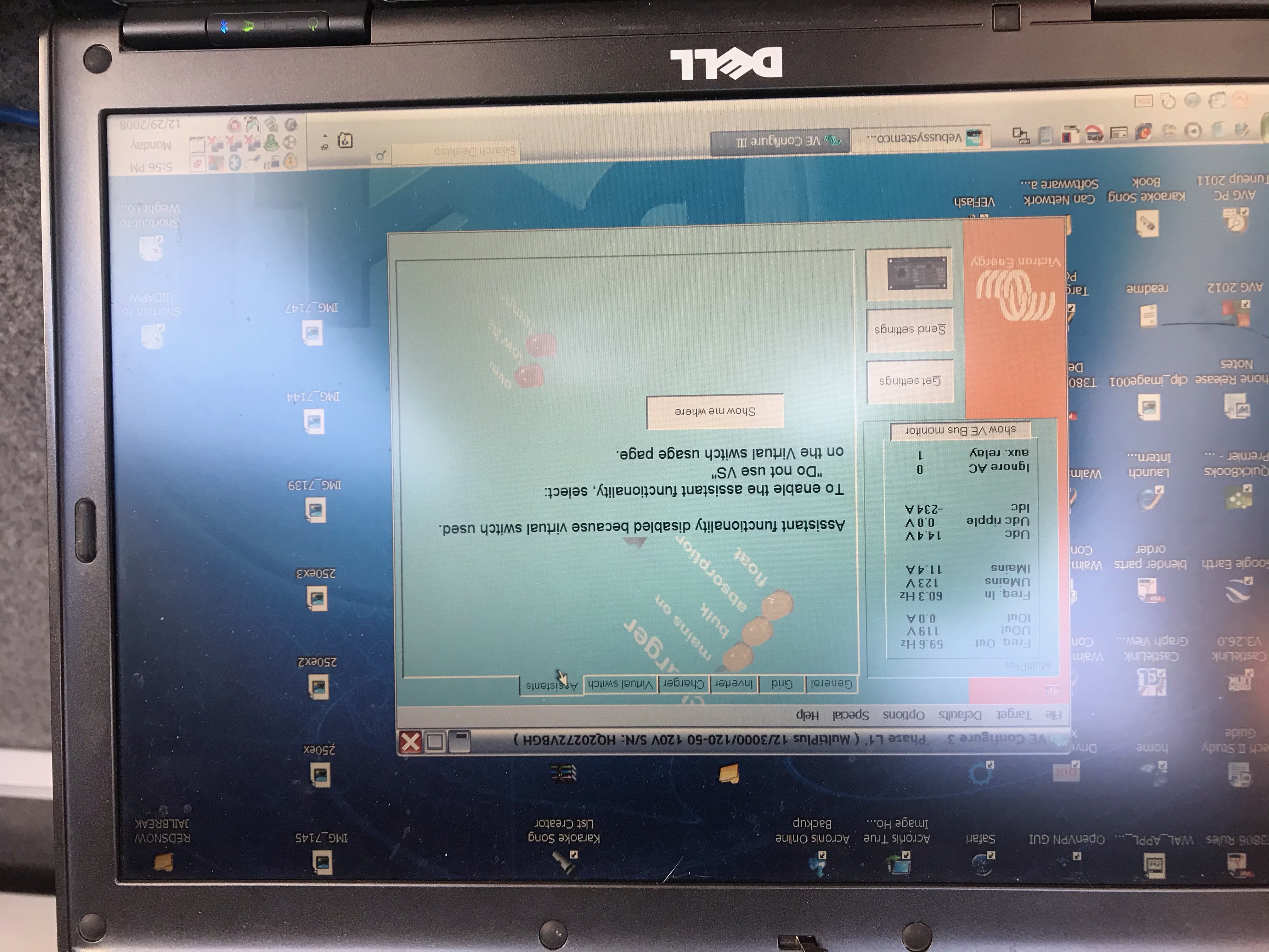
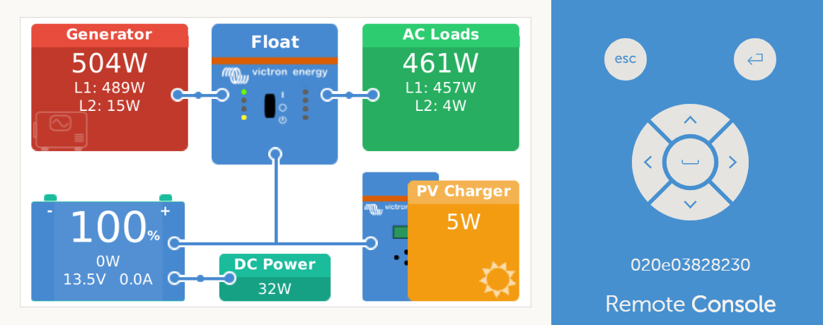
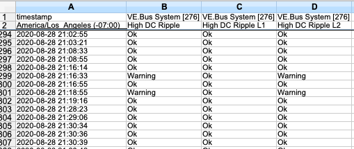
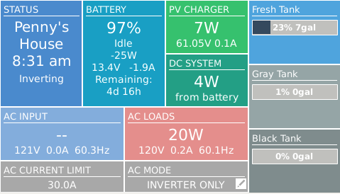
Second Image is when I transferred back to Shore Power. My Oasis Hydronic Heater may be using some of this 12v load for its pumps and such but why does it increase as I am inverting. Puzzled I am. Any Wisdom would be appreciated

0 Likes 0 ·
Joshua Warren avatar image Joshua Warren rjoustra commented ·

Firstly, can't see your pics. Please check the links.

The AC loads showing up as DC loads could be a number of things, but we'd need more information about how you configured everything and what kind of shore power (120, 120/240, etc) you're providing. For example, if you configured the inverters separately (using VE configure for each individual inverter but without using VE.bus System Configurator to configure the group) and are providing only 120VAC input that the inverter on L2 is inverting from the batteries to supply its AC loads (with the batteries, in turn, being charged by the inverter on L1) and hence the Cerbo could see those AC loads as DC because it's unaware of the second inverter.

Also, did you charge those batteries up individually before putting them all together in parallel?

0 Likes 0 ·
rjoustra avatar image rjoustra Joshua Warren commented ·

Inverters are configured in split phase 180 120/240. Each inverter feeds its own leg of the AC Breaker Panel (Inverter 1 Load1 Inverter 2 Load2) They are being fed by two banks of 5 Battle Born batteries each of equal cable lengths tied to a common set of buss bars (everything DC lands on these buss bars Smart Shunt 1000a, 2 Multi 3000 Inverters, Cerbo GX, and all the DC loads of the RV). Both inverters cable lenths on the DC side are within a few inches of each other due to disconnect placement next to each other and the AC cable is about 3 feet longer for the L2 inverter. Power comes in from a Shore or generator through a transfer switch over a 6/4 cable through a 50 amp circuit breaker then separates into 2 6/3 cables one feeding each inverter then out of each inverter is a 6/3 to another 50 amp breaker where they are combined back into a 6/4 cable feeding the RV breaker box. In both of the pics above the DC loads never changed in the RV. Let me know if any more detail is needed. I would send screen shots of the config but I have not figured out how to look at it without being connected to the inverters just yet. LOL Newbie Here. I know I am running with the UPS and Dynamic current limiter both on. The battery setup is per battle born I did not change those settings. And I remember it was split phase 1 AC input. If you can explain how to look at the config file I have for them without being connected that would be great or I will connect later and take screen shots

0 Likes 0 ·
Joshua Warren avatar image Joshua Warren rjoustra commented ·

Can you try reposting the images? The links are coming through as broken. In the meantime I'll give it some thought and see if anything comes to mind. Your system is very similar to mine and I'm also a n00b but I've had some success in figuring out seemingly magical combinations of config parameters that make things work more-or-less as desired.

0 Likes 0 ·
rjoustra avatar image rjoustra Joshua Warren commented ·

Also why am I getting Low Bat and Overload warnings on both L1 and L2 when on shore power. The AC that was running all night is on L2 but everything else in the RV was basically dormant.

0 Likes 0 ·
Joshua Warren avatar image Joshua Warren rjoustra commented ·

What shore power connection are you using right now? Is it 120/240 or just 120?

Send a picture of your inverters so we can see the lights on the front. If the second inverter did not switch over to shore power and is inverting then the consumption of that AC will exceed the charging capacity of the first inverter and hence your batteries will discharge. You will not be able to run an AC on L2 with 120V single phase input continuously with your configuration due to the fact that after conversion losses the amount of continuous power available on L2 is probably going to be under 1200 watts. I got around this by rigging up a 20A light switch that allows me to switch my second AC over to L1 when I'm on 120V single phase input; in that configuration I can run the pair of air conditioners simultaneously and short duration loads are supplemented by power assist from the inverter on L1.

0 Likes 0 ·
rjoustra avatar image rjoustra Joshua Warren commented ·

I am showing L2 in the Shore power box on GX display. When I have none it is blank would it not be blank for L2?

0 Likes 0 ·
Joshua Warren avatar image Joshua Warren rjoustra commented ·

That sounds right, but pictures are worth a thousand words. A screenshot of your Cerbo's remote console (or a cell phone pictures of the Cerbo display itself) would really help. And if you can provide a VRM link that would be good too.

What DC voltage and state-of-charge are being reported at the time when it's throwing low battery warnings?

0 Likes 0 ·
rjoustra avatar image rjoustra Joshua Warren commented ·

Here is a minute ago


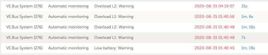
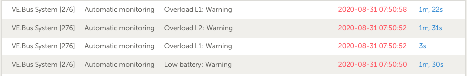
And another low bat and overloads to follow
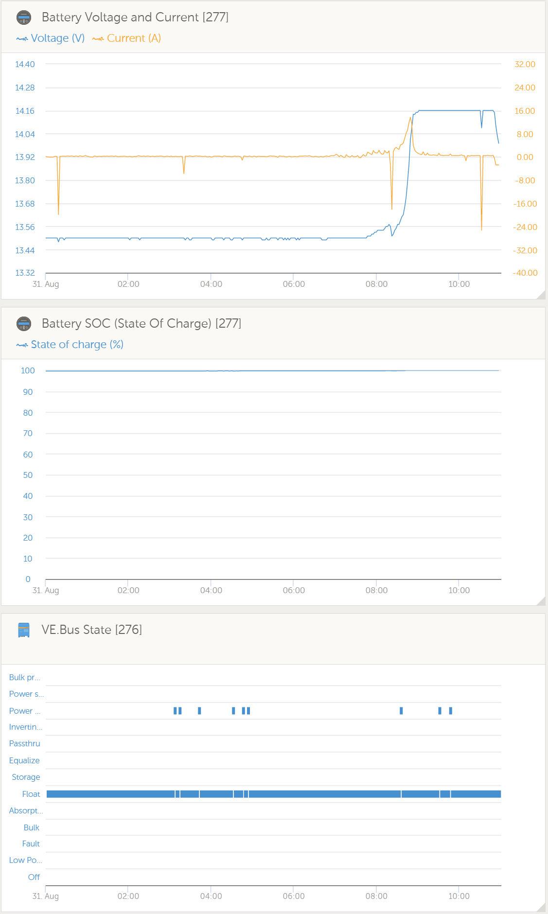
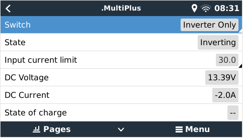
0 Likes 0 ·
Joshua Warren avatar image Joshua Warren rjoustra commented ·

That looks good, now pull up VRM and check out SOC and DC voltage along with VE.bus state. See pic below. I believe those low battery warnings should show up as "faults" and if we have SOC and DC voltage at those points in time we can start to get an idea of what's happening.

0 Likes 0 ·
1598886170930.png (111.7 KiB)
rjoustra avatar image rjoustra Joshua Warren commented ·

Here you go. Obviously the ones at 1ish and 4ish in the morning we were asleep and the only thing running was 1 AC unit on L2 and 1 Electric water heater coil on L2. All of the loads on L1 are pretty much the outlets in the coach (Laptops and cell phone charges etc)

0 Likes 0 ·
rjoustra avatar image rjoustra rjoustra commented ·

I did add the pic of the inverter tab below. I missed that one. The only difference between 1 and 2 is the ground relay box is checked on Inverter 1 and unchecked on inverter 2. They are very quiet when they are on charger only. lol Just some real expensive battery chargers.

0 Likes 0 ·
Joshua Warren avatar image Joshua Warren rjoustra commented ·

From this it looks like the rogue DC current is no longer present. But I'd double check to make sure that none of the batteries have a path to ground that does not go through the shunt. And it doesn't look like the low battery alarms triggered a "fault" -- do you know the points in time when they occurred? And are those times reflected in the plots?

Looks like the inverters switch to "invert" for a bit overnight. Do you have the AC input and voltage plots? Was the AC input cut off at some point?

BTW, you should test all your functionality on 30A single phase input if you intend to plug into 30A service at RV parks and have everything "just work." I had to do some squirrelly reconfiguration for that scenario.

0 Likes 0 ·
rjoustra avatar image rjoustra Joshua Warren commented ·

Ok so the larger spikes in dc voltage are most likely due to one inverter switching to inverting while the other is still charging. Still don't quite understand why the increase with the AC load increase from like 10 to 30 plus amps dc. No I did not charge each individually when I got them from battle born. Each 5 battery circuit read 13.43 and 13.42 respectively. I can shut down one 5 battery bank to let them charge then do the same with the other if that would help, breaking them down to individual batteries would be a major pain given there location but I would do it if that solved my issue. I can't rule out shore power issues at this park as we have had low voltage before but I do have a buck boost transformer to raise the voltage if it drops below 110 it will boost 10%. As far as running on 30 amp I thought I might either leave them and let 1 inverter invert while the other passes and charges, once the solar is up and running this shouldn't be too much of an issue in so cal.

0 Likes 0 ·
Joshua Warren avatar image Joshua Warren rjoustra commented ·

Let's clarify something real quick. When you had those rogue DC loads, were they showing up as "DC System" draw or just draw from the batteries? If it was draw from the batteries then it could be the inverters going into power assist mode briefly to overcome the locked-rotor amperage of the air conditioner(s). If it was battery draw and not sustained for very long then that's almost certainly what it was and I wouldn't worry about it further. If it was "DC system" draw that's a separate matter. Did you install all this stuff yourself? If not, I'd disconnect the battery banks from the shunt and then do a continuity test to ensure there's no other path to ground.

As for the low voltage stuff, I don't really know where to go with that unless you can identify exactly when they occurred and post the relevant screenshots of VRM so we can see the system's state at those times.

0 Likes 0 ·
rjoustra avatar image rjoustra Joshua Warren commented ·

Inverter 2

Inverter 1

0 Likes 0 ·
img-3093.jpeg (2.0 MiB)
img-3094.jpeg (2.2 MiB)
img-3095.jpeg (4.1 MiB)
img-3096.jpeg (3.6 MiB)
img-3098.jpeg (4.0 MiB)
img-3099.jpeg (3.0 MiB)
img-3100.jpeg (2.9 MiB)
img-3097.jpeg (4.1 MiB)
rjoustra avatar image rjoustra Joshua Warren commented ·

Also this morning inverter 1 is chattering for 30s and then back to normal but when inverting its not at all. When it does it it is switching back and forth to inverting it seems. Shore power is steady

0 Likes 0 ·
rjoustra avatar image rjoustra Joshua Warren commented ·

Now that they are both under a load there is now switching or chatter earlier there was almost no load on inverter 2 and about 600w and inverter 1. Nevermind I lied inverter 1 just chattered

0 Likes 0 ·
Kevin Windrem avatar image Kevin Windrem rjoustra commented ·

My best guess is the clatter is the AC input relays opening and closing. If so, there is something going on that is causing one or both of the Multi's from accepting incoming AC. I believe both AC inputs will be dropped if either one is rejected.

Is the voltage dropping when AC input current draw increases? This could cause the input to be rejected, but then when the current is zero the voltage goes back up making the incoming AC acceptable again.

A diagram could be very useful in helping us to diagnose your problems.

The history provided by VRM would also be useful. It's difficult to provide the detail necessary with screen shots. You can share your VRM portal to us via a URL you can post here. Otherwise, we need to see a minimum screen grabs of the following parameters zoomed in where a fault has occurred:

  • Grid voltage/current
  • AC load voltage/current
  • VE.Bus System DC voltage/current
  • VE.Bus Warnings and Alarms
  • Inverter mode
  • Battery voltage/current
0 Likes 0 ·
rjoustra avatar image rjoustra Kevin Windrem commented ·
0 Likes 0 ·
rjoustra avatar image rjoustra rjoustra commented ·

When going through and checking all my AC connections coming in and isolating loads I did find two things Load 2 had a not as tight as I like connection and some previous owner of the coach had a piece of 10/4 in between the surge protector and the transfer switch, I'm surprised it has not caused issues before but I am sure these inverters are way more sensitive to the incoming power. The ends were a little charred. It was only a piece about 2 foot long which may be why it has not been a big issue. It now has 6/4 as required.


0 Likes 0 ·
rjoustra avatar image rjoustra Kevin Windrem commented ·

Should I have the ground relay box checked on my inverter tab for either inverter. I am still getting a situation where Ac loads will drop to zero and shore power goes to the negative on L1 then draws from the battery for about 20 seconds then recovers. Rinse and repeats every few minutes? I currently have it selected for inverter 1 only per another user with a similar rv build as mine. Also this doesn’t seem to happen when on the generator only shore. Although I have only run for about 20 mins.

0 Likes 0 ·
Kevin Windrem avatar image Kevin Windrem rjoustra commented ·

You certainly want at least one Multi activating it's ground relay when detached from AC input. I can see an argument for doing it on only one inverter in a split-phase/3-phase system but don't know it would make a huge difference. Not sure what Victron recommends either. In any case the ground relay won't be a factor in your negative shore power flow as the ground relays would be open with AC input active regardless of the setting in VE Configure.

I'm assuming you are not running an ESS configuration which might allow feeding power back onto the grid. I have seen extremely brief negative AC input power in my system due to a load that switches a heating element on and off rapidly (maybe 10 times a second).

0 Likes 0 ·
rjoustra avatar image rjoustra Kevin Windrem commented ·

I am seeing it only on L1 even when nothing in the coach is changing certainly not every few minutes on average. Any idea why this might be happening on shore power and for the limited time I ran the generator it did not seem to and no ESS. It does not do it when charger only is selected. I even tried disconnecting my buck boost transformer. No difference. Do you think my surge protection device could be causing this and why just L1 if that were the case. And it is throwing an overload warning each time it does. Wasn’t sure I mentioned that part

0 Likes 0 ·
rjoustra avatar image rjoustra rjoustra commented ·

By switching off dynamic current limiting it seems to have taken care of the errors that I was seeing on L1

0 Likes 0 ·
Joshua Warren avatar image Joshua Warren rjoustra commented ·

FWIW I've had my best experience with dynamic current limiter enabled and power assist boost factor maxed out at 3.5.

0 Likes 0 ·
rjoustra avatar image rjoustra Joshua Warren commented ·

In reading the info on Dynamic current limiting it will slowly load a generator. I have a 12.5k generator so don't think that is going to be a real issue. Is there more that it does?

0 Likes 0 ·
Show more comments
rjoustra avatar image rjoustra Joshua Warren commented ·

I have switched them to charger only to avoid the chatter. Figure it can't be good on the contacts

0 Likes 0 ·
rjoustra avatar image rjoustra Joshua Warren commented ·

Couple Pics of the install

0 Likes 0 ·
img-3105.jpeg (2.4 MiB)
img-3103.jpeg (2.5 MiB)
img-3102.jpeg (2.4 MiB)
Joshua Warren avatar image Joshua Warren rjoustra commented ·

Nice looking system. Your wiring is certainly a lot cleaner looking than mine.

Is the input coming from the power grid or a generator? My system sometimes behaves oddly when using my truck's (supposedly pure sine) inverter as AC input.

And regarding the rogue DC current, can you confirm that all of your batteries' paths to ground goes through the shunt? I.e. there's no other grounding? I only ask because if somehow one bank had a ground upstream of the shunt then when the batteries were first tied together and slight charge imbalances were evening out you could wind up current flowing through the shunt and then back through the other ground thus creating the illusion of net current flow out of the batteries.

Just saw the VRM pics; I'll review them now.

0 Likes 0 ·
rjoustra avatar image rjoustra Joshua Warren commented ·

Currently coming from Grid. But it is a 12.5kw Genny which can supply the whole coach

0 Likes 0 ·
Joshua Warren avatar image Joshua Warren rjoustra commented ·

Your MPPTs aren't connected via VE.direct to the Cerbo and hence aren't showing up in the console. The result is that any current from the MPPTs/solar is going to be accounted for in the "DC Power" block. When you said you saw a big unaccounted for DC amp draw, was that in the DC Power block? If the number was negative, then what you were seeing was the solar panels sending power into the system, not amperage draw.

If you pick up a USB hub and VE.direct to USB interfaces (one for each MPPT) you can connect all the MPPTs to the Cerbo via USB. Here's what my console looks like (it says "generator" but it's actually on grid input right now); if you connect the MPPTs to the Cerbo you'll see the "PV Charger" block as well.

0 Likes 0 ·
1598904656691.png (106.4 KiB)
rjoustra avatar image rjoustra Joshua Warren commented ·

Sorry yes they are but I do have them shut off since I do not have the panels in yet. Wanted to eliminate possible other issue causing my problems. Here is my URL https://vrm.victronenergy.com/installation/70323/share/16ce0934


0 Likes 0 ·
rjoustra avatar image rjoustra rjoustra commented ·

Also my connection is cellular so don't expect any great response if you try monitoring the Cerbo Display. lol It works just not to quick

0 Likes 0 ·
Joshua Warren avatar image Joshua Warren rjoustra commented ·

Unless I missed it, you still have not told us exactly when these low voltage and rogue current events took place. I don't think I can help you without this information. If we knew that then the VRM link you provided would help us figure out what was going on with the rest of the system at that point in time.

And were the MPPTs connected (panels or not) when these events occurred? We really need you to paint the complete picture here because there are so many variables.

0 Likes 0 ·
rjoustra avatar image rjoustra Joshua Warren commented ·

No the Mppt's were not connected when the events occurred. The log shows at 1ish and 4ish this morning. Others have happened but I figure you can see those two to better diagnose. Thank you again for everyones participation trouble shooting these issues.

0 Likes 0 ·
rjoustra avatar image rjoustra Joshua Warren commented ·

Rough drawing of the system layout

Battery configuration (disconnects not shown here)Round trip cables are the same length.


0 Likes 0 ·
Kevin Windrem avatar image Kevin Windrem rjoustra commented ·

I couldn't add parameters to your VRM but downloaded the raw data and took a quick look in a spreadsheet.

Some of your overloads may be justified. I saw 2700 watts on occasion.

Low battery alarms may also be justified. Saw numbers below 12.7 volts. Also saw high ripple alarms. Ripple alarms are a very good indicator of too much voltage drop from the batteries to the inverters.

This system is capable producing 6000 watts at the inverter outputs. Factoring in inverter efficiency, that's an AVERAGE of more than 500 amps of battery current. But variations that roughly follow the AC voltage waveform can be expected. You can expect current peaks approaching 750 amps with both inverters at full load. At these currents, any wire should be considered a resistor and appropriate measured taken to minimize voltage drops and balance drops in parallel paths.

One 4/0 cable from each battery bank isn't going to get the job done.

You also should run the same length cables to from battery to a common point. At the very least, run separate equal length 4/0 cables from each end of each battery bank (2x4/0 for positive and 2.x4/0 for neg).

0 Likes 0 ·
rjoustra avatar image rjoustra Kevin Windrem commented ·

Ok I though by splitting the bank into two I would also divide the load between the banks, those cables are rated at 445 amps.and I am only running about 10 ft of each positive and 10 feet of neg. Each inverter is only recommended to be fused at 400 amp. The cross section of those cables more than meet victrons specs. According to the manufacturer their 4/0 has a cross section of 165mm2 and each 2/0 has a cross section of 94mm2 x 2 should be appx 188mm2 coming from the inverters to the buss bars. Did I read something incorrectly on Victron Specs? And I laid out the cables the way they showed in the wiring unlimited I just ran one a certain direction and the other the opposite in order to conserve my cables and the need to buy more red. Is it not the round trip length with DC that matters or does the fact that one positive is longer and one is shorter and just the opposite for the other bank. The round trip lengths are the same to the buss bars, the positives are a bit longer once you account for the disconnects in the equation.


Not sure but now I am a bit confused. lol

0 Likes 0 ·
rjoustra avatar image rjoustra Kevin Windrem commented ·

May I ask where are you viewing High DC Ripple at?

0 Likes 0 ·
Kevin Windrem avatar image Kevin Windrem rjoustra commented ·

If you download the VRM data, it has a column for a high ripple alarm. Lots of data in that table. I couldn't find a way to show this in the Advanced graphs but it might show up in the VE.Bus Warnings and Alarms if they exist.

0 Likes 0 ·
Show more comments
rjoustra avatar image rjoustra Kevin Windrem commented ·

I have exported all the data from my VRM account and I can only see 2 instances of High DC Ripple during the first day of start up. Is there somewhere else this data would show up or do you think this might have been just some start up growing pains?


0 Likes 0 ·
Kevin Windrem avatar image Kevin Windrem rjoustra commented ·

You are right. I thought I'd seen more ripple alarms. The other odd thing is these were reported when the inverters were in absorption mode (not supplying the AC load power).


Also a lot of the overload warnings are when the inverter is in passthru or absorption mode and power is no where near max power output but elevated temps (36 C) could have reduced the available power so that 2000 watts could have triggered an overload warning.

0 Likes 0 ·
Show more comments
marekp avatar image marekp rjoustra commented ·

I do not think it is a good idea to install those MPPT-s one above the other.

The top one will likely overheat.

0 Likes 0 ·
rjoustra avatar image rjoustra marekp commented ·

Thank you for that advice since there is no room really anywhere else I suppose another small fan is in order.

0 Likes 0 ·
trip-tracks avatar image
trip-tracks answered ·

For such a large system, you should consider 24V or even better 48V.

The 48V particularly will reduce the cost of your system considerably as the 48V inverter/chargers are less expensive, the solar regulators only need to be 1/4 of the size of a 12V system and the cabling only needs to be 1/4 the rating.

Even a 24V system will reduce everything to half.

There are lots of positives. Especially with 2 x 3000 inverters that have the potential to pull 500-800A from the batteries - and you do need to combine the banks. A 48V system will typically only pull around 100-125A under full load.

Kevin has already covered the need for system monitoring - the Cerbo is the way to go - it will bring all the components together and also push data to the VRM and aprovide alarms and email notifications.

Have fun!

3 comments
2 |3000

Up to 8 attachments (including images) can be used with a maximum of 190.8 MiB each and 286.6 MiB total.

Kevin Windrem avatar image Kevin Windrem commented ·

I agree about 48 or at least 24 volts. Then use a DC-DC converter to power the RV's DC loads. These will generally be small - under 50 amps probably, maybe even less.

0 Likes 0 ·
rjoustra avatar image rjoustra Kevin Windrem commented ·

Yes I would also lose the ability to use the assist from the house batteries when the coach chassis batteries get low for some reason. I have a switch on the dash that ties the two House and Chassis banks together in this instance.

0 Likes 0 ·
rjoustra avatar image rjoustra commented ·

Yes I had considered this and if this was an off grid system or a travel trailer or fifth wheel I would have absolutely gone that route but it is in my motorhome and to keep it simple since the chassis is all 12vdc that steered my decision. Thank you for the input.

0 Likes 0 ·
marekp avatar image
marekp answered ·

"Each inverter positive and negative go directly to the the buss bars using two 2/0 for both pos and neg "


I think there should be a fuse between positive buss bar and MultuPlus battery terminal.

2 |3000

Up to 8 attachments (including images) can be used with a maximum of 190.8 MiB each and 286.6 MiB total.

rjoustra avatar image
rjoustra answered ·

Ok so silly question here. Battleborn is willing to return the two 12 3000 inverters for two 24 3000 and I would need to order a DC to DC converter. Would it be acceptable to leave the 2 banks wired in parallel and series the two banks together as shown here in my drawing or would I need to pull them all out and completely start over? Essentially wiring together 2 500ah Batteries. I know this will totally solve my voltage drop issue but not my overloads as I believe those are caused by the temp of the units (although I only saw the battery temp in the data so not sure where that is being measured) and them handling less watts which would not make any difference in the 12 or 24 volt models. Battleborn also had me set my low battery pre alarm at 12volts vs 13 which should help eliminate the low bat warnings especially after I go ahead and add the second positive and negative cables to the banks.

Is the benefit of going 24v at this point worth changing everything around removing and reinstalling both inverters and adding the DC to DC converter especially since I am seeing no DC ripple even as configured and discharging the batteries to their 1000ah level and seeing at the battery a voltage of 12.5. If all things being equal and the drop remains about the same throughout the the discharge cycle that would put me at a inverter voltage of about 12v well above my 11.5 cut off and adding the additional cables will only improve that scenario? Sorry I meant to move that last negative on the right up to the top battery.


27 comments
2 |3000

Up to 8 attachments (including images) can be used with a maximum of 190.8 MiB each and 286.6 MiB total.

Joshua Warren avatar image Joshua Warren commented ·

I haven't seen any mention of this yet so maybe I missed it (or other measures have been taken to mitigate it), but having ten batteries in parallel means that your mean time between failures is likely to be relatively low. And when one battery fails it may begin to eat the others; I guess this may not be that big of a deal if the system is either in a state of discharge or charge and not being left sitting idle like an off-grid install might be. But it's something to think about if there's a possibility of returning some/all of this stuff (perhaps with a restocking fee) and using fewer larger-capacity batteries. For example, I have two 300 AH Victron lithium batteries.

If I had to do mine all over again I'd be looking at the 24V Multiplus and Tesla 24V modules. More of a science project but also far more AH/$, and AH/lb.

0 Likes 0 ·
rjoustra avatar image rjoustra Joshua Warren commented ·

Jersey Dirtbag

I don't think returning the batteries is an option the freight alone would be hefty if they charged me no restocking fee so I would be using the same just configured shown above if possible and I would not be downsizing my charge controllers either as that ship I think has sailed (no boxes or anything since we are full-time there was no room to store) So the inverters are the only thing on the table.

I guess my question to both of you is as I stated, change or work through the issues with the voltage loss which again I believe (and I will test for sure today) never really dropped below 12v in its current configuration so additional cable will improve that.

Kevin

My thought on the two banks was that it divided the load of each bank capable of carrying 440 amps max on the cables, so if the inverters both started pulling 6000 watts peak load the 500 amp load would be evenly distributed over the two banks and the 4/0 cables feeding them. When I thought of wiring them as one bank I assumed I would need to fuse it for for the peak load and increase the interconnect cables to handle that much load. This may have not been the best plan? Just like paralleling the Inverters onto one AC Line they share the load so I applied that to the batteries when deciding what would be best. This is obviously something I could change just not sure how much cable length I would save in doing so and would my 350amp disconnect handle 400 amps continuous and 6000 peak.

So for argument sake could I combine the banks into one by moving the short positive off of one fuse and the short neg off of the shunt land those on the neighboring bank to create a single bank keeping the one 400 amp fuse and the one 350 amp disconnect. This would not shorten anything going to the batteries (18" interconnect cables and the 2.75' positive to fuse and 2.75' neg to shunt, but would eliminate the second disconnect and the cables for it. Would this save me anything do you think. I suppose I can test it by shutting down one bank to see if this is an improvement and put a 4000w load on only five batteries. I assumed my results would be the same, but I will check.

Let me put together a more accurate layout of my batteries to paint a clearer picture for y'all to help with.


0 Likes 0 ·
Joshua Warren avatar image Joshua Warren rjoustra commented ·

I don't think there's any good way to connect ten batteries in parallel; even though the batteries are in two physically distinct "banks," they are banks of batteries in parallel, and the banks themselves are in parallel, so I would figure that as long as the cable runs to each battery are equal and kept to a distance such that the voltage drop is acceptable (I don't really know what "acceptable" is for a 12V system, to be honest) that this thing should work. Putting the batteries in series will create its own issues with balancing and the need for a step-down converter(s) for 12V devices (plus the difficulty of using the system as a backup engine start battery) so it's not clear to me that changing over to that configuration at this point is going to increase your chances of making things "just work". A better use of time and resources would be reconfiguration your space to get the inverters as close to the batteries as possible; 20 freakin' feet of cable seems like a whole lot. If they have to be that far I'd probably start looking at 2x 4/0 AWG runs all the way from each "bank" to each inverter. Disconnects are going to get pretty squirrelly...probably have to tie the pairs of 4/0 into a bus bar and connect the switch to the bus bar with copper bar stock and then split it on the other side of the switch the same way.

0 Likes 0 ·
rjoustra avatar image rjoustra Joshua Warren commented ·

Had a disturbing instance happen today. I had left the inverters in charger only because of the crazy power here at our park which I thought would be a good solution for bad power. However in the 115 degree heat wave the power cycled on and off like three times sending the inverters in to an error state leving the coach without power. Are there any setting I can modify that would allow the inverters be passive. They won't handle switching the load when running at even 1800watts in this heat or at best they were able to switch it once. Can I set an assistant to wait a few minutes before turning ac back so incase there is a drop out like I saw it will allow the mains to switch back on?


My poor dog was not happy today. She was a little warm after 4 hours no power.


Thanks Again


0 Likes 0 ·
Kevin Windrem avatar image Kevin Windrem rjoustra commented ·

115 Yikes! I'm guessing shore power was being pushed to the limit from everyone's air conditioner. Probably brown out conditions.

I added a bypass switch to run loads off shore power directly if the inverter fails. There's no way to do this internally because of the internal architecture - the inverter/charger core is always connected to the load.

Not sure about assistants delaying return to shore power. Someone else may know.

You can switch to "Inverter Only" which rejects shore power and runs loads on the batteries. You can't get that from the stock Mobile Overview page but can in the Multiplus Switch menu. I've modified my Mobile Overview page extensively and added the Inverter Only selection.


0 Likes 0 ·
rjoustra avatar image rjoustra Kevin Windrem commented ·

That was the other thought. I was planning on putting in a rotary transfer switch so one position power goes through the inverters and the other disconnects out going power and passes it straight from shore to my ac panel while also powering up the inverters so the batteries stay charged. I figured as long as the transfer switch disconnects the out going loads from the inverter I should be able to run the inverters at the same time they just won’t be seeing an current draw except to charge the batteries. If that makes sense? Figured it best not to back feed AC to the output side of the inverters. Lol

0 Likes 0 ·
Kevin Windrem avatar image Kevin Windrem rjoustra commented ·

Yes, exactly.

3 pole-double throw (need to switch the neutral also)

0 Likes 0 ·
rjoustra avatar image rjoustra Kevin Windrem commented ·

I did order a 3 pole but I had not considered switching the neutral or ground for that matter as it is continuous throughout the entire system. Is the neutral switched inside the inverters? If so then I understand why the need is because if you ever switch off the inverters you would lose your neutral and your circuits would become wildly out of balance. Perhaps I will bring all 4 over from the disconnect on the line side of the inverters to the disconnect that is on the load side of the inverters parallel the ground and switch the neutral with 2 legs. Thanks

0 Likes 0 ·
Kevin Windrem avatar image Kevin Windrem rjoustra commented ·

Yes, the AC input relay disconnects both the hot AND neutral. So your bypass needs to switch both hots plus the neutral (3 poles). Also, the "ground relay" in the Multi connects the neutral from the inverter core to safety ground when the AC input relay opens so the neutral is at ground potential.

You should NOT switch the safety ground ("PE"). All safety grounds will be bonded together.

0 Likes 0 ·
rjoustra avatar image rjoustra Kevin Windrem commented ·

Yes I will go ahead and switch both legs and the neutral as well as bond the two disconnect grounds through that same 6/4 cable since that ground for the disconnects flows through the inverters. Just in case either of those were to come loose or I need to remove the inverters for some reason, essentially creating a jumper cable for the ac as a whole. Thanks for the advice...

0 Likes 0 ·
gbntx avatar image gbntx rjoustra commented ·

The bypass switch comments got me looking up how to do it.

This diagram's wiring may work for me.

mortonsonthemove-solar-phase-3-1

0 Likes 0 ·
rjoustra avatar image rjoustra gbntx commented ·

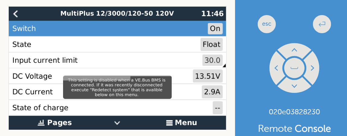
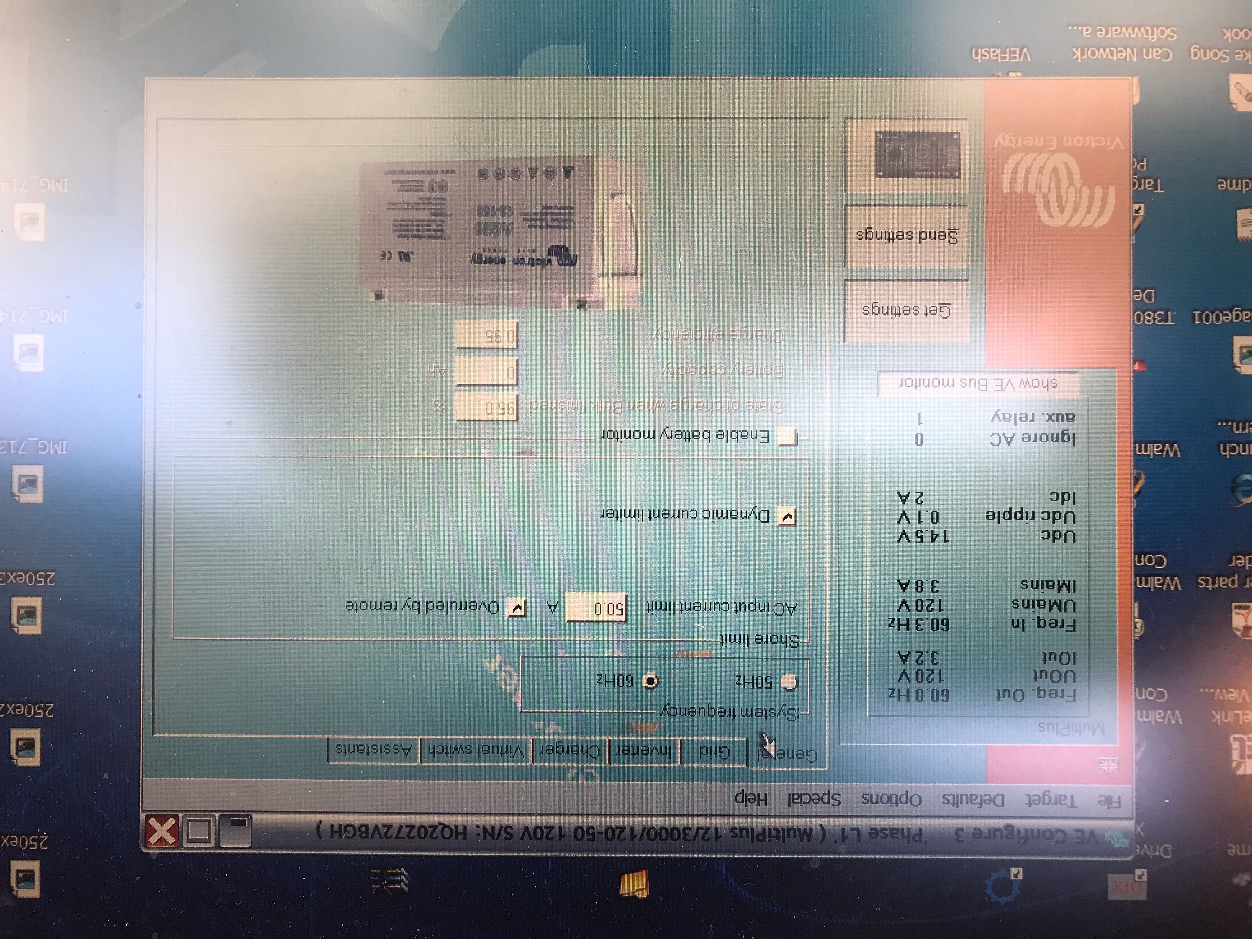
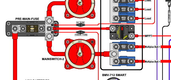
Yes exactly only mine has 2 multis I will be switching. Thanks for the diagram from the Mortons. https://smile.amazon.com/gp/product/B07H5GZ53G/ref=ppx_yo_dt_b_asin_title_o01_s00?ie=UTF8&psc=1


0 Likes 0 ·
Joshua Warren avatar image Joshua Warren Kevin Windrem commented ·

When you say "Multiplus Switch menu," are you talking about the Virtual Switch tab in VE.configure? If not, what/where is this functionality located? I'm new to this equipment and haven't heard of it.

I just enabled the "show boat and motorhome overview" functionality (I wasn't aware of this either, so thanks), but can you elaborate on what you mean by having "modified" it? I don't see any options to modify anything; it's simply an on/off button.

Thanks for sharing your knowledge.

0 Likes 0 ·
1599402227094.png (74.3 KiB)
rjoustra avatar image rjoustra Joshua Warren commented ·

My cerbo doesn’t have show boat or motorhome box or I have not found it, but I can switch to inverter only in the inverter menu.

0 Likes 0 ·
Kevin Windrem avatar image Kevin Windrem rjoustra commented ·

Once you enable Show boat & motorhome overview as Jersey says, is shows up as an additional page in the rotation.

The Multiplus Inverter Only selection is in the Multiplus menu.

The modifications I made to the Mobile Overview page were done by rewriting the code. You can see the system in INVERTER ONLY in the AC MODE selector at the bottom.

The enhancements requires replacing a file and adding another. Details are here:

https://github.com/kwindrem/GuiMods

The tanks display that shows gallon is yet another modification that started to support SeeLevel tank sensors. Details of that mod here:

https://github.com/kwindrem/TankRepeater

1 Like 1 ·
Joshua Warren avatar image Joshua Warren Kevin Windrem commented ·

Very cool. I have Victron batteries and a VE.bus BMS so the Venus's control over the inverters is disabled. Hmm...

Is your code written in Python?

0 Likes 0 ·
1599407224113.png (87.2 KiB)
Joshua Warren avatar image Joshua Warren rjoustra commented ·

It's under "Display and Language."

Can you screenshot your "inverter only" option? I don't see that in mine.

0 Likes 0 ·
Kevin Windrem avatar image Kevin Windrem commented ·

BattleBorn would be better positioned to answer the question of series connecting the banks or parallel connecting pairs of batteries in series. I really don't know which is best.

I honestly don't know if switching to 24 volts is worth it at this point. You'd still have issues with distance between batteries and voltage monitoring (the shunt in your case). True, the voltage drop would be less if the same area of copper was used from your existing system. In the drawing above, you did cut the amount of copper in half so same voltage drop but that's half as a percentage of battery voltage.

0 Likes 0 ·
rjoustra avatar image rjoustra Kevin Windrem commented ·

Okay so here was a test I did and these were my readings both at the beginning and end of the test. I thought it went well and will only improve a bit more with the addition of 2 more 4/0 cables on each bank at the opposite ends which will decrease my voltage drop as I believe you both have suggested.

L1 up to 2150 watts with no overload

L2 up to 1705 watts with no overload


Batteries pulling around 5000 watts 389.5a DC


Readings at the beginning of test


Inverters

L1 12.64 - 12.61

L2 12.65 - 12.62


Batteries read 13.08 - 13.13

0.05 volt variation at almost every point in the bank.

Terminals directly connected to fuses are the lower readings


Buss bar reads

12.72


Readings at the End of test


Inverters

L1 12.15vdc

L2 12.16vdc


Battery Voltage

12.48vdc


Buss Bars

12.22vdc


912 ah used before I hit my low battery warning. Which I didn’t get down to the 12vdc that battleborn suggested I reprogram and were unsure why they programmed it for 13vdc originally.

The system must warn you a little before you hit that voltage is all I can figure because as you can see I hit 12.15 and 12.16 at the inverters and higher voltages everywhere else it could measure.


No DC ripple in VRM data


A couple of Overload warnings towards the end all seemed justified based on temps of the inverters figuring each would only give about 2000 watts and we breached that a couple times during the test.


1 temp warning on L1 towards the end in the last 10 min of the test.


So do you think she is a keeper? lol


0 Likes 0 ·
Kevin Windrem avatar image Kevin Windrem rjoustra commented ·

I'd add the second 4/0 from each battery bank. Those two paths calculate to 0.17 volts of drop each so that's 0.34 volts of your ~0.5 volt total drop (battery to inverter). So you should see a total voltage drop reduce to around 0.25 volts with those extra 4 cables.

With the cable distances you outlined, I don't see any way to improve the actual voltage drop to the inverters, but getting the shunt closer to the batteries would provide a better system view of BATTERY voltage. That would require combining the separate paths through fuses and disconnect switch WITHOUT reducing the amount of copper in these runs. Not sure it is worth it if you can accept a less accurate battery voltage indication while under load.

The inverter specs seem to accept a wide voltage range so I don't think they will suffer from the voltage drops you are experiencing.


0 Likes 0 ·
rjoustra avatar image rjoustra Kevin Windrem commented ·

I am going to add those cables for sure and I thought keeping my shunt powered at the mid point in the two banks, then I have the multi volt sense at the beginning of the bank which I can see in the inverter info on the cerbo and using the mid point voltage monitor on the shunt for my buss bars. This should give me a good idea where all the voltages stand at any give time. I think its the best I can hope for without rethinking battery positioning which would make horrible use of the little space I have. We do live full-time in the motorhome so space is at a premium.


I want to thank both of you for sticking with me and working through the issues and educating me along the way to better understand my system and why it was doing some of the things it was doing.

Thanks Again

Richard

0 Likes 0 ·
Kevin Windrem avatar image Kevin Windrem rjoustra commented ·

Getting the shunt's positive connection closer to the batteries would be a great idea but since you have two banks with separate disconnect switches you can realistically monitor only one bank. Connecting the shunt's positive lead to both battery banks creates a connection between the two banks that can't begin to handle the possible currents should you open one of the two disconnects or one of the fuses blows. That was the main reason I was looking for ways to make it one bank of 10 batteries.

0 Likes 0 ·
rjoustra avatar image rjoustra Kevin Windrem commented ·

Strongly agree that would be a bad idea. lol. My hope is that having the extra 4/0 cables will narrow that 13.08 - 13.13 variation I was seeing at different points on the batteries.

Question? You both pretty much understand how I have things wired so is a second set of 400a fuses necessary close to the inverters. In Victrons wiring unlimited they don't show one in the examples being on both sides of the disconnect although they do show it in the schematics.

My thoughts are unless the inverters started to go into an overload I will be hard pressed to blow my battery fuses as it is, since the load is divided amongst both banks. I would have to see over 800 amps before my fuses come into play and the 4/0 are rated at 440a and the 2 2/0 combined are rated for 650a so they should not be in danger of ever melting down before the battery fuses blow and shutdown the inverters. Correct?


The only thing I could potentially see is maybe one inverter having a catastrophic overload and burning up the other one before a fuse blew? Thoughts?

0 Likes 0 ·
Joshua Warren avatar image Joshua Warren rjoustra commented ·

The inverters are each only capable of charging at 120A, so as long as each individual cable (i.e., one of the 2/0 even if you're using 2x 2/0) can handle that maximum charging current, I don't think you need a fuse on the inverter side. I guess the counterargument would be that some kind of internal failure in the inverter could cause all of the AC input to be converted to DC and thus far exceed the current capacity of the inverter wiring, but that would also have to coincide with an external short circuit (otherwise the battery voltage would prevent the runaway charging current) between the battery fuse and the inverters.

Personally, I think the probability of such an occurrence is vanishingly small, so it's not immediately obvious to me why your inverters need their own DC overcurrent protection (provided the conditions I mentioned above are met). I used the Lynx distributors in my system which require fusing so my inverters are fused but I don't really think it's necessary for our applications (which are very similar).

0 Likes 0 ·
Kevin Windrem avatar image Kevin Windrem rjoustra commented ·

A fuse close to the inverter is recommended to guard against faults inside the inverter. These fuses should be sized to blow with excessive inverter current. I can't recommend one way or another about adding fuses here but do believe your concerns are valid.

The fuse close to the battery is to protect the system wiring from shorts or other faults. However your fuse is a LONG way from the batteries and a short in those cables between the batteries and fuse is at least as likely as faults after the fuse. Placing these fuses as close as possible to the batteries improves safety and reduces fire risk. That said, there will always probably some wiring that is before the first fuse.

It's especially important to guard against possible shorts in the cabling before the fuses. Anywhere the cables pass metal supports or other sources of a ground connection, including running along with the negative battery cables, additional insulation should be used with fasteners to prevent vibration that could erode insulation.

The batteries do have overcurrent protection but check with Battle Born to determine what happens after a large overcurrent. The batteries could reset and apply voltage again only to create another fault. Rinse and repeat until the protection circuitry in the batteries fails.


0 Likes 0 ·
rjoustra avatar image rjoustra Kevin Windrem commented ·

One quick question about adding these second set of 4/0 cables to each battery bank.

Since one pair on each bank will be shorter and one pair longer than each other will this create an imbalance in the draw on the bank with the current taking the path of least resistance?

And if I make both sets the same length am I defeating the purpose of adding the second set of cables at that point?

Thanks again

0 Likes 0 ·
Kevin Windrem avatar image Kevin Windrem rjoustra commented ·

Can't say for sure either way but cables should be the same length for best balance across the bank.

You are already somewhat compromised by the daisy-chain parallel cables (rather than star) so it is really hard to say what will provide the best balance. You might even try moving the cables from the end to the second battery on each end.

Experiment with the system under a significant load. Measure each battery voltage and adjust cable placement for best balance.

0 Likes 0 ·

Related Resources

Additional resources still need to be added for this topic