question

mblowes avatar image
mblowes asked

Transfer to AC IN on one phase in 3 phase system

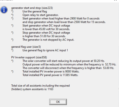
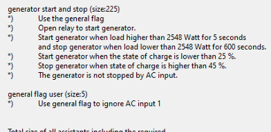
1. 3 phase system with 6 3kVA Multiplus in off grid config. To maximise solar consumption I have set up assistants (general relay plus either programmable relay or gen start / stop will do this) to transfer to AC IN once the battery discharges to a certain level. This is set only on the master on L1 and will use the chargers on all the Multis. Works well.

2. But when inverting again an overload can occur on L3 due heavy loading. I dont have time to rebalance phases just at the moment so was hoping to emulate the assistants above to solve this too. But it does not work.

If Ioad the logic on L1 Master.. it does not affect L3 (unlike the voltage sense/ charging assitant in 1. I tried either the programmable relay or gen start/stop relay on the L3 master , plus the general relay assistant, but nothing happens.


Note the PV assistant is in place on all masters.. and is the last assistant.

Is it possible to get L3 to transfer to AC on overload condition during inverting?

I had no problem setting this up on a single phase system to test.. so my assistant logic works.. it just does not in a 3 phase set up.

Multiplus-II3 phaseAssistants
1 comment
2 |3000

Up to 8 attachments (including images) can be used with a maximum of 190.8 MiB each and 286.6 MiB total.

mblowes avatar image mblowes commented ·

so to be clear.. i want the whole system to switch to grid when battery voltage falls to x .. but I also what l3 to switch to grid with its load (during inverting) exceeds a wattage

0 Likes 0 ·
5 Answers
mblowes avatar image
mblowes answered ·

Solved it.. gosh this Victron kit is ridiculously gorgeous to work on. Extreme logic..

On another post I saw a reference from Mr Boonstra about treating the 3phase unit as one unit. Penny dropped.

The general flag relay is shared among units.. so by using it to ignore AC IN on L1 (for purposes of battery voltage) it was not available to L3 for Overload. It was only L3 that has the overload problem.

I cleared the assistants on L1 and put them all on L3 in form of gen start / stop activating general flag for both battery voltage and overload.. Viola.. it works.

But a small new problem developed.. a low , oscillating hum... not sure if true but seemed like using L3 as the master did not work... so I remapped the phases in the VE Bus configurator and that problem was sorted too ie L3 -> L1, L1-> L2 and L2->L3.

All good now.. so switches (as a group since PV assistant is loaded) if either a) voltage is low or b) there is an overload on L1 (formerly L3).


2 |3000

Up to 8 attachments (including images) can be used with a maximum of 190.8 MiB each and 286.6 MiB total.

daryl avatar image
daryl answered ·

@mblowes Is there a reason why you can't just use ESS and leave it grid connected to acheive the desired outcome?

2 |3000

Up to 8 attachments (including images) can be used with a maximum of 190.8 MiB each and 286.6 MiB total.

mblowes avatar image
mblowes answered ·

Short answer this is my first big project and I'm learning. First stage of commissioning is for it to do what I want in off grid mode.


Ultimately it will move to ESS.. but my understanding is I have to load the grid code (Australia) to run that (at the moment it is set as none).. And doing this means that the 3 Goodwe inverters on AC OUT export all excess - and this is not adjustable. It is a 3 to 6 month wait until smart meters are uninstalled here and we are not supposed to export until that happens.

1 comment
2 |3000

Up to 8 attachments (including images) can be used with a maximum of 190.8 MiB each and 286.6 MiB total.

daryl avatar image daryl commented ·

I would have thought to be compliant you would have to set the grid code since you are actually connected to the grid some of the time.

0 Likes 0 ·
mblowes avatar image
mblowes answered ·

Need to reopen.


1. I wont be moving to ESS.. I dont wish to put in the grid code / export

2. I cant get the start gen/gen flag to work on more than one phase for overload condition.

Any ideas ?

Config: 3 phases ( 2 x 3kVa Multis on each) , 3 ɸ AC In ie one ɸ to each phase of multies. 3kW of PV on each AC OUT so PV Inverter assistant is installed.screenshot-2022-06-11-at-145559.png


2 |3000

Up to 8 attachments (including images) can be used with a maximum of 190.8 MiB each and 286.6 MiB total.

clay123 avatar image
clay123 answered ·

HI @mblowes - can you assist on how you got your scenario in point 1 above to work well ?

im dealing with 6 5kW multiplus and trying to cut of ACIN charging from grid at a certain SOC for the batteries.

4 comments
2 |3000

Up to 8 attachments (including images) can be used with a maximum of 190.8 MiB each and 286.6 MiB total.

mblowes avatar image mblowes commented ·

I only ever got that to work by voltage. I did not use the SOC calcultated in the Multiplus. I found this quite reliable in my situation. It was about knowing key voltage levels then considering timing and possible excursion events in my system. I get SOC today from an Octo GX.which I'm more confident of , . there is almost certainly a pathway to trigger the gen start from that - I just have not spent the time to figure it out.. Sorry I could not be more helpful.

0 Likes 0 ·
mblowes avatar image mblowes commented ·

I never did solve point 2 , nor found solution elsewhere in this community? Is Victron considering training AI on its own datasets? A BoonstraAI would be awesome, both for me , and believe long term for Victron.

0 Likes 0 ·
Alexandra avatar image Alexandra ♦ mblowes commented ·
@Clay123

In the meantime Node Red has been offered, it has much more flexibility.

And Victron connect which also offeres an easy way to conditionally connect to AC.

Then there is a way to use the generator control on the GX (using the GX relay to signal the aux 1 or 2) to manipulate the AC input with easily adjustable parameters.


0 Likes 0 ·
mblowes avatar image mblowes commented ·

I have got this to work with SOC rather than Vdc now.. the assistant setup I'm using is below. 1. You have to enable the charge monitor in the the first multiplus on phase 1 (ie Charge Master unit) 2. Also.. I could never get this to accurately assess SOC when it was just the multi. But I now have a Linx 1000 plus Octo GX reporting SOC and this seems to be passed up the VE.Direct Bus to the Charge Master. This SOC appears to be synched and for me highly accurate.

The good thing about this is that as the systm approaches my 25% SOC limit it doesn't false trigger when a large load is engabled.. which tended to happen when using Vdc.


Assistants: there are 2.. Basically when the 25% threshold is breached it lets the AC in.. ie the unit acts like the default state.


Hope this helps.


1708582249951.png

0 Likes 0 ·
1708582249951.png (59.2 KiB)