question

tobi17 avatar image
tobi17 asked

Chargery BMS on Venus OS

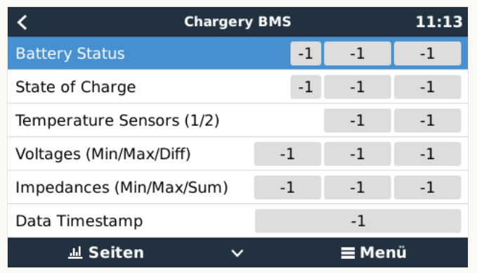
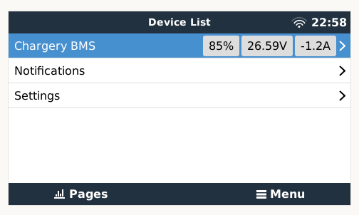
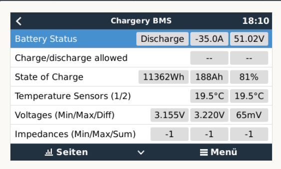
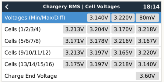
I have enhanced my Chargery BMS driver for Venus OS a lot and it want to share my code! Maybe we can get other BMS data as well to be displayed on Venus/Cerbo etc... My source code (surely open source) is available at https://github.com/Tobi177/venus-chargerybms and surely Victron is allowed to embed it to Venus OS! :) It even have an install script now! :)

Maybe my code can be helpful for any developers! Victron, thank you for your open source support! Much appreciated!


Bye

Tobi

BMV Battery MonitorBMS
chargerybms.png (323.6 KiB)
overview.png (360.1 KiB)
4 comments
2 |3000

Up to 8 attachments (including images) can be used with a maximum of 190.8 MiB each and 286.6 MiB total.

Magnus Pernemark avatar image Magnus Pernemark commented ·

@tobi17 I don't understand how to hook it up. The Chargery BMS has USB ports, the Cerbo GX has USB ports. The FT232RL has a usb port and pins. Where do you connect the pins?

0 Likes 0 ·
mswoboda avatar image mswoboda Magnus Pernemark commented ·

You put the FT232RL with USB in the VenusOS Device (Venus, Cerbo, Raspberr...). The chargery has a COM output with two wires. Plus and Minus. Here you have connect the correct polarity of the pins to the COM Port on ChargeryBMS.

0 Likes 0 ·
alan avatar image alan commented ·

Does this supply the battery monitor in the multi with the BMS's SOC via DVCC?

0 Likes 0 ·
Magnus Pernemark avatar image Magnus Pernemark commented ·

@Tobi17 I have to run the VenusOS-large image (V2.70-4-large-16) and this chargerybms plugin will not work. SOmething with DBus name already exists.
If I switch back to V2.65-7 it works. Switching back to V2.70 does not work.
Could you take a look at that? (I opened a github ticket)

0 Likes 0 ·
16 Answers
mvader (Victron Energy) avatar image
mvader (Victron Energy) answered ·

Really cool @Tobi17! I can’t tell now if we’ll embed it though - but really nice.

2 |3000

Up to 8 attachments (including images) can be used with a maximum of 190.8 MiB each and 286.6 MiB total.

Phil Gavin avatar image
Phil Gavin answered ·

@Tobi17 This is very nice.

1.) Will it need to be updated with Venus/Chargery firmware update?

2.) Does it cover up to the Chargery 24T BMS?

It might swing my choice of BMS.

Regards


2 comments
2 |3000

Up to 8 attachments (including images) can be used with a maximum of 190.8 MiB each and 286.6 MiB total.

tobi17 avatar image tobi17 commented ·

Hello Phil,


1) Yes, currently you need to reinstall it. There could be done some stuff with the persistent storage for users on the venus devices, but at the moment I do think reinstallation after Venus OS updates are the best solution.

2) The driver itself should cover all three Chargery BMS 8/16/24! Please do not expect the driver to be fully tested with all different options, but if there would be any problems I am glad to fix the issues.

You need to know, that you must adapt some qml files (for the gui) to display your 24 cells on voltages/impedances page. But this is very easy and done in minutes.


Bye

Tobi

0 Likes 0 ·
Phil Gavin avatar image Phil Gavin tobi17 commented ·

Thank you for for your time on this.

0 Likes 0 ·
aaronsb avatar image
aaronsb answered ·

I just referred someone to a Victron solution based on the fact that you wrote a serial driver for chargery. :)

1 comment
2 |3000

Up to 8 attachments (including images) can be used with a maximum of 190.8 MiB each and 286.6 MiB total.

tobi17 avatar image tobi17 commented ·

It is possible :)

0 Likes 0 ·
tededd avatar image
tededd answered ·

@Tobi17 This looks great. Am I right in understanding this makes all the data shown visible remotely through VRM remote console, though data logs not available through widgets on the advanced tab. Also this is this pure info rather than BMS control data directing the Victron kit to reduce charge etc as is poss over the CAN-bus? Cheers, Edd

1 comment
2 |3000

Up to 8 attachments (including images) can be used with a maximum of 190.8 MiB each and 286.6 MiB total.

tobi17 avatar image tobi17 commented ·

No, VRM support is currently not available. I have checked it, but it seems at the moment VRM support is very limited. As far as I know/tested, it is not easily possible to track/submit custom values to the VRM. Nothing we can solve yet!

0 Likes 0 ·
mswoboda avatar image
mswoboda answered ·

Hi Tobi,

Thank you very much for sharing your Software!

Unfortunately I cannot run it. I installed it as you described, I inverted the Tx Signal of the FTDI FT232RL Chip and I see as values only "-1". In the Devices settings of the "Chargery BMS" everything seems o.k.

My system is: 3 Multi2 5000, 3 MPPT VE.Can 250/100 and a CerboGX and the Chargery 16

Any ideas?

Thank you in advance!

Best Regards,

Michael


5 comments
2 |3000

Up to 8 attachments (including images) can be used with a maximum of 190.8 MiB each and 286.6 MiB total.

tobi17 avatar image tobi17 commented ·

If all values are "-1", then the Chargery driver is detected and working - but it receives no data from the Chargery BMS! Please check the connection between your FT232R and your Chargery BMS. This is wrong, you need to wire ground and rx/tx!

0 Likes 0 ·
mswoboda avatar image mswoboda tobi17 commented ·

Thank you for your answer! I just saw it today (I didnt receive a notification... have to check that!)

O.k. I tought that but I do not understand exactely your answer:

"This is wrong, you need to wire ground and rx/tx!"

I have 2 cables from the chargery and I wired the ground and the ((reversed)Tx as you said in your description.

How should I wire both rx AND tx as you said?

Thank you for your help!

0 Likes 0 ·
mswoboda avatar image mswoboda tobi17 commented ·

IT WORKS!!!!!! YES, YES, YES! I AM SO HAPPY, THANK YOU TOBI!!!

I reversed also the Rx and put the cable on Rx and now it works!

So again for all other folks who want to try this: If its not working use the Rx and not the Tx Port on the FT232R chip!

Thank you again, now I can watch the cells. For me it is helpfull because I use now a different cell balancer (active 2A balancer), and the chargery is only the BMS and balancing is turned off. I had bad experience with the chargery as a balancer.


0 Likes 0 ·
yuwire avatar image yuwire mswoboda commented ·

@mswoboda So just confirming, you connected from COM3 on the Chargery RED to Rx and BLACK to ground?

0 Likes 0 ·
mswoboda avatar image mswoboda yuwire commented ·

Yes exactly, still working.

After a few days it hang up, and I have to restart the Cerbo.

0 Likes 0 ·
mswoboda avatar image
mswoboda answered ·

Hi Tobi,

again my question: I did all what you said in the documentation and every value I can see is "-1".

I am not sure how to change the qml file.

Can you help me. I really want to need your tool.

Best Regards,

Michael

2 |3000

Up to 8 attachments (including images) can be used with a maximum of 190.8 MiB each and 286.6 MiB total.

mswoboda avatar image
mswoboda answered ·

Here are the screenshots:

screenshot1.png

screenshot2.png

screenshot3.png

Help me Obi-Wan Kentobi you're my only hope!

;-)


screenshot1.png (50.2 KiB)
screenshot2.png (54.0 KiB)
screenshot3.png (60.8 KiB)
2 |3000

Up to 8 attachments (including images) can be used with a maximum of 190.8 MiB each and 286.6 MiB total.

capptn avatar image
capptn answered ·

Hi,


I am very grateful to you for the code you provided.


With the help of your code, i created my own driver to integrate a LIONTRON LiFePo4 battery into Venus OS.

It works very well too.

But...

Do you know if it is possible to use the driver as a system battery monitor?


I can select it but no data is displayed in the GUI.

bildschirmfoto-2020-11-28-um-141800.png

bildschirmfoto-2020-11-28-um-141812.png


Thank you again for charing your code!!!


4 comments
2 |3000

Up to 8 attachments (including images) can be used with a maximum of 190.8 MiB each and 286.6 MiB total.

tobi17 avatar image tobi17 commented ·

No, I cannot tell you if you can use the driver as system battery monitor. I do see the same problems, but I use a BMV-712 for this purposes.

0 Likes 0 ·
capptn avatar image capptn tobi17 commented ·

Thanks for your answer,

i have already solved the problem by using the required Path´s of a battery (https://github.com/victronenergy/venus/wiki/dbus).

E.g /Dc/0/Voltage or /Soc or /Dc/0/Current. Than I can use my LIONTRONBMS Driver as main battery monitor. I also have a shunt (Victron SmartShunt 500A) but there where big difference between the Soc´s after a time.

So I only need the BMS of the lithium.

0 Likes 0 ·
tobi17 avatar image tobi17 capptn commented ·

Perfect! Great work!

0 Likes 0 ·
mswoboda avatar image mswoboda tobi17 commented ·

@capptn Can you tell me what you where you changed the path?

I also want to use the SOC in the VE.Canbus system.
If I set it, I have no values. Sounds like the same problem you had...

Thank you, would be a great help!

0 Likes 0 ·
Magnus Pernemark avatar image
Magnus Pernemark answered ·

I need some help.
I have installed on my Cerbo GX.
I used the 2-wire cable that came with the Chargery, put the red cable on TX and the black on GND on a USB to TTL RS232 board. It is a FDTI chip on it.
I used FT PROG to invert the signals. Programmed. And plugged it in to a USB on the Cerbo GX (and the connector in the Chargery BMS)

Cerbo GX finds a USB, says it is a chargery bms.
All I see is -1:s

(I did try and switch the red cabe to RX, but same result)

What to do?

1609026515910.png1609026471666.png1609026360982.png


1609026360982.png (25.5 KiB)
1609026471666.png (21.4 KiB)
1609026515910.png (27.0 KiB)
13 comments
2 |3000

Up to 8 attachments (including images) can be used with a maximum of 190.8 MiB each and 286.6 MiB total.

Magnus Pernemark avatar image Magnus Pernemark commented ·

@tobi17 Something is really wrong. I have two FTDI devices in my Cerbo GX. One is a RS485-USB for the Energy Meter (ET340). The other is for Chargery BMS. The RS485-USB is ttyUSB0, but is mapped as ttyCHGBMS01. The chargery is connected to ttyUSB1. How do one change this? The energy meter is not working anymore after installing this script and Chargery BMS ofcourse only show -11609447520067.png

0 Likes 0 ·
1609447520067.png (111.1 KiB)
Magnus Pernemark avatar image Magnus Pernemark Magnus Pernemark commented ·

Fixed it temporarily..
Since both FTDI adapters are named the same thing, one have to include the serial numer of the device.

I removed the chargerybms from "# The USB RS485 has..."

and added a separate entry with the specific serial number.
1609459947511.png


after a reboot I see both
1609460093723.png


Can the install script have a "Enter serial number?" input?

0 Likes 0 ·
1609459947511.png (111.6 KiB)
1609460089187.png (64.7 KiB)
1609460093723.png (64.7 KiB)
Magnus Pernemark avatar image Magnus Pernemark Magnus Pernemark commented ·
0 Likes 0 ·
yuwire avatar image yuwire Magnus Pernemark commented ·
0 Likes 0 ·
Magnus Pernemark avatar image Magnus Pernemark yuwire commented ·

Almost! The original code does not use the Chargery BMS as a battery monitor within Venus OS, my version does.

My version also handles fake FTDI chips. Fake FTDI chips often have the same serial number, which makes Venus OS confused. I added the ability to enter a serial number of the FTDI chip.

Deviation from original code

  • Use The Chargery BMS as a Battery Monitor
  • GUI is default for 16 cells
  • No custom overview page
  • Allow usage of fake FTDI chip (or atleast address the issue)
0 Likes 0 ·
yuwire avatar image yuwire Magnus Pernemark commented ·

@magpern I managed to get the Fake FTDI chip working without programming, just put the positive wire on RX and the negative wire on the GND. What I'm trying to work out is how to display both Chargery BMS's. I have two identical banks and it only shows one. I was under the impression that your github code would make each one unique and display them individually. It doesn't make a difference if it's two fake chips or one fake and one real. It will only display 1 BMS like below. Any hints on how to get multiple BMSs displayed would be greatly appreciated!

1612843130758.png

0 Likes 0 ·
1612843130758.png (16.8 KiB)
Magnus Pernemark avatar image Magnus Pernemark yuwire commented ·

If you have two BMSes, which one should Victron use controll SoC?

Anyway, no, my version of the code does not enable usage of two or more Chargery BMSes. I think the code can be changed to enable this, but I will not do that (have only one, and it is in production).
The code registeres a device on the VeDeBus with connection as key, which is hard-coded.

'connection'  : "com.victronenergy.battery.ttyCHGBMS01" 

But there would need to be other changes as well. It would need to set up a separate linux service and much more. My knowledge about this is very limited.

Regarding usage of two fake FTDI. In my system I have a power meter ET340 and the chargery BMS connected to the same Cerbo GX. The ET340 is hooked up with a RS485-USB adapter, and it uses a fake FTDI chip, and the Chargery is hooked up with a RS232-USB with a fake FTDI chip.
The two adapters will not coexist, unless their serial number is used as identity, instead of the description.

It is as if Venus OS will just read "FDTI Adapter" and take the first one.

You will not be able to use two FTDI with the same serial number, I was fortunate to have two fake adapters with different serial numbers, one with just zeros and the other with A50285BI

0 Likes 0 ·
yuwire avatar image yuwire Magnus Pernemark commented ·

Ok, thanks for the information. It is my misunderstanding of the code. I never intended to use the BMS as the SOC, I have a BMV-702 that can do that. I was just wanting the BMS info so I could monitor remotely each battery pack.

Have limited programming experience so all this is very new, the learning curve has been steep. I'm thankful for people like yourself that openly share code and take the time to respond.

0 Likes 0 ·
gnagflow avatar image gnagflow Magnus Pernemark commented ·

Hi magpern,

was just in the mood to try it a year later again with toby's great invention on another build. I used your modification, after much trouble i got it to run. Everthing seems to work, but not the cell impedances, any idea? Its a 16S build.


1616692342774.png

1616692470591.png


thanks a lot.

Please keep us updated when you get the Venus OS Large running and implemented the DCL CCL to use the chargery to control the victron. :-)

kind regards,

by the way, also the dischage end voltage is always jumping between values of <0V to >60V.

1616692496187.png


0 Likes 0 ·
1616692342774.png (67.8 KiB)
1616692470591.png (74.1 KiB)
1616692496187.png (8.2 KiB)
mswoboda avatar image mswoboda Magnus Pernemark commented ·
Hi Magnus,

I would love to use your adaption.
I had the script of Tobi in the past and it was working.

But I also want to use the SOC for battery monitor.

I have a original chip and it was working with tobis software.

But if I run yours nothing is happen in the remote console...

Do you think my original chip is the problem?


0 Likes 0 ·
Magnus Pernemark avatar image Magnus Pernemark mswoboda commented ·
I am no longer using the chargery. It is not optimal for a battery for your home.

I switched to diyBMS, it has some Canbus support for victron.

0 Likes 0 ·
mswoboda avatar image mswoboda commented ·

It seems that the FDTI Chip doesnt send data.

If there is a light on it, is it blinking all the time (i.e. its transmitting data)?

I know that there a lot of chips on the net which are not working.

I would also try the following: You can test your FTDI chip to see if it is working. You use a jumper to connect the Tx und Rx port. With putty (or similar) you open a Terminal connection to the FDTI. The data you send (typing letters in) you have to receive.

Just google for "Loopback test FDTI" and you will find a detailed description.

Then you will be sure if your chip is working before you do Software troubleshooting.

0 Likes 0 ·
mswoboda avatar image mswoboda mswoboda commented ·

Ah, sorry didnt see the post, where you fixed it already...

0 Likes 0 ·
Paul B avatar image
Paul B answered ·

Hi tobi17 just setup the program on our Cerbo with 2.60 fw

Looks Really good , have found two issues.

1. One once you select the screen on the Cerbo you then CANT move off the screen by using the touch screen or when using remote with the mouse. HOWEVER by pressing the esc button you do get the option to move screen.

2. as you can see the time and date are large and there is no data in the green area (there wont be in the red area as no solar contented), however the data is in the settings screen.

I have tried selecting the Chargery as the default monitor as well but this made no difference.

have you any suggestions as to how for fix these display issues

Chargery units is a BMS8T 300 amp shunt but am only using 4 cells at this time

1610937113869.png

1610937350691.png


The below are the raw steps that I ended up using.

I used the standard Victon USB to 485 interface cable ASS030572018

FTDI Adapter FT232RL USB TTL Serial (IMPORTANT: Must be flashed with FT_PROG software to invert tx mode)

I used putty as the Terminal connection via my local network

It seems you have to log in twice

root@192.168.3.5

password ???

Then logged in again for ssh I could not go straight in with the below login

ssh root@192.168.3.5

password ???

wget https://github.com/Tobi177/venus-chargerybms/raw/master/install/install.sh

chmod +x install.sh

sed -i -e 's/\r$//' install.sh


./install.sh

  • reboot the CCGX


1610937113869.png (39.8 KiB)
1610937350691.png (51.2 KiB)
2 comments
2 |3000

Up to 8 attachments (including images) can be used with a maximum of 190.8 MiB each and 286.6 MiB total.

tobi17 avatar image tobi17 commented ·

1) Tap on the Caption "Overview Label" on the top and then you should be able to switch to the menus. "Enter" key also works.

2) You need to update the device sources within the "OverviewTiles.qml" files. Please check: https://github.com/Tobi177/venus-chargerybms/blob/master/gui/qml/OverviewTiles.qml#L9

3) Since I do not use a Cerbo I do not know why the font is that large. This might be fixed, once all data is displayed, but I am pretty sured this can be fixed at the qml files as well.

First step is, to get all of your deviced running.


Bye

Tobi

0 Likes 0 ·
yuwire avatar image yuwire commented ·

I've noticed that with a custom screen, to switch screens by the touch, you need to click and drag on the header. No other place on the screen is responsive.

0 Likes 0 ·
alan avatar image
alan answered ·

So, des this allow allow the BMS to control the victron gear? DCL, CCL etc??

26 comments
2 |3000

Up to 8 attachments (including images) can be used with a maximum of 190.8 MiB each and 286.6 MiB total.

Magnus Pernemark avatar image Magnus Pernemark commented ·

I personally have not tested to have the BMS limit by temperature, since I always have above freezing where the batteries are placed. But I use it to report state of charge to victron, and victron respects the values from the BMS.

I have run the code for a week or two. I think there is some stability issue. After some time, venus os stops listening to the incoming data from the BMS and the values freeze.
After a reboot of venus os, the values update again. How to fix this, I don't know.

0 Likes 0 ·
tobi17 avatar image tobi17 Magnus Pernemark commented ·

My code is working here for a couple of months and there seems no issues within the driver software code. It does not have any stability issues. You need to check your hardware environment.

Very rarely I do see the Chargery suddenly rebooting. I run my chargery with the "external batt" switch directly connected to the battery with a schottky diode. Just because to improve the voltage measurements.

external-power-supply-from-battery-2.png

0 Likes 0 ·
tobi17 avatar image tobi17 tobi17 commented ·

Just to add, this graphics is provided by the developer of the Chargery BMS. If you want to use the "external battery switch" and connect it to your battery, you should use the above diode.

0 Likes 0 ·
Magnus Pernemark avatar image Magnus Pernemark tobi17 commented ·

I have had it running for 1 week now without hanging. But it has been mostly idle, since here in the nordics sun is a rare thing this time of year.
In my case, the updates just stopped. It was stuck at 22% SOC but on the chargery it was 12%. I rebooted Cerbo GX, didn't touch Chargery. Then SOC updated in Cerbo GX.
Chargery is powered of mains with a 3A 24V transformer so power to Chargery is not a problem. Cerbo is also powered from mains from the same transformer.

I don't doubt that you code is not working, it "smells" like the USB or the FTDI gives up after a while. I do run a fake FTDI chip.
I will do more hands on error searching if it hangs again. Now I have just rebooted Cerbo GX remotely.

0 Likes 0 ·
doubleohwhatever avatar image doubleohwhatever Magnus Pernemark commented ·

How has the stability been?

0 Likes 0 ·
Magnus Pernemark avatar image Magnus Pernemark doubleohwhatever commented ·

It is still unstable and cannot really be used in a production environment. You cannot trust it.
The code for Chargery is not at fault, but every now and then Venus OS (in my case on a Cerbo GX) stops listening to the data.
SOC is locked to what it was when the update stopped, let say 50%. Victron thinks it is 50% and will discharge battery. Battery becomes empty, but victron thinks it is 50%. Chargery triggers the emergency shutdown with the contactor cutting power to victron. Victron does not like being abruptly cut off, and will not start again. So, you will be in a state where nothing works.

If I see that the update has stopped, before this happens, everything is fixed by rebooting the Cerbo GX. As soon Cerbo GX is online again, the real SOC is updated.

This hanging happens about once a week.

possible solutions

automatic reboot every day
watchdog that reboots only the integration
investigate if this is caused by using a fake FTDI chip (i have a fake chip)

0 Likes 0 ·
doubleohwhatever avatar image doubleohwhatever Magnus Pernemark commented ·

That's a shame. There is another option though. An arduino with a can bus shield could read data from the charger and forward the battery data to the cerbo via can bus:

https://github.com/Tom-evnut/VEcan

This might even be a nice all-in-one board for the project:

https://www.longan-labs.cc/1030008.html

My only concern would be non-opto isolated can bus connection creating a ground loop. That may not be an issue though.

0 Likes 0 ·
alan avatar image alan doubleohwhatever commented ·

I would wait to see if a genuine FDTI chip still causes the issue. Also the new chargery BMS is about to be released, the new P series will have RS232/485 & CanBus (a Bidirectional protocol) so that is a big win,

0 Likes 0 ·
yuwire avatar image yuwire alan commented ·

How can you tell a Geniune FDTI vs fake?

0 Likes 0 ·
Magnus Pernemark avatar image Magnus Pernemark yuwire commented ·

If your serial number is A50285BI or 00000000 then you most certainly have a fake chip because that is a popular serial number which is written to fake chips

0 Likes 0 ·
yuwire avatar image yuwire Magnus Pernemark commented ·

YUP! I have two with me that have A50285BI. I'll give it a try and see if I come up with the same issues.

0 Likes 0 ·
Magnus Pernemark avatar image Magnus Pernemark yuwire commented ·

Great! If you have more than one fake FTDI connected to the venus os, you have to use my version of the Chargery BMS code. (I have two, one rs485 to usb with fake chip, and this rs232 to usb with fake chip).
And again, the "hanging" occurs very infrequently. Last time mine hang was Thu 28.01.2021 01:57:53
Since then I have rebooted my Cerbo GX at least twice (for other stuff, not related to the hanging). I run my Cerbo GX from grid power (BMS too)

0 Likes 0 ·
Show more comments
kevstone122 avatar image kevstone122 doubleohwhatever commented ·
Hello. I justhave the same problem, that after 1 week the timeStamp get frozzen? Is there any solution?

Is it possible to make some reconnect in the python script?

Thank you!

0 Likes 0 ·
gnagflow avatar image gnagflow Magnus Pernemark commented ·

Unfortunately in my case i have the same problem, it hangs up every while after some days. i have to reboot the venus gx. I use an original FTDI chip, no fake.

0 Likes 0 ·
yuwire avatar image
yuwire answered ·

So I've got multiple BMS8Ts that I am trying to get to show up. Wondering if there is anyone that could point me in right direction to get this working. So far I've been able to get the Units to show up on the GUI as shown below. This will change if I plug in 1, 2 or 3 of them. BUT what happens is that when there are multiples no information shows up(but works on a single connection). The second also shows with no info.

1613284779971.png

Disclaimer, not a programmer so just working through this by trial and error. Because the driver has a hardcoded connection to the dbus I created a second (and third) unique 'driver'

1613284998717.png

1613285026228.png

Then added the lines into 'start-chargerybms.sh'

1613285096659.png

Not sure where to look next. I'm thinking all adpaters are maybe getting addressed the same thing and there is a conflict? Any assistance would be appreciated Thanks!


1613284779971.png (22.9 KiB)
1613284920435.png (10.3 KiB)
1613284998717.png (10.9 KiB)
1613285026228.png (10.7 KiB)
1613285096659.png (15.5 KiB)
2 |3000

Up to 8 attachments (including images) can be used with a maximum of 190.8 MiB each and 286.6 MiB total.

Paul B avatar image
Paul B answered ·

Hi @Tobi17 , Just need some setup help with your chargery software I have it installed and its working but not all the screens have installed on the CCGX running FW 2.72

also is it possible to run 2 x Chargery BMS units on the one CCGX using 2 x USB ports and how would the GUI display work, I can understand that the Device displays would would. and I am aware that the RS232 interface would need different serial numbers. If you could help out please let me know I can also give you VRM access to the site if thats of help , please email me at service@octopusasia.com and ill send you a VRM invite for that site. happy to pay for your time t help out here.

There are missing screens - plus I only have this screen on the CCGX GUI being the below picture

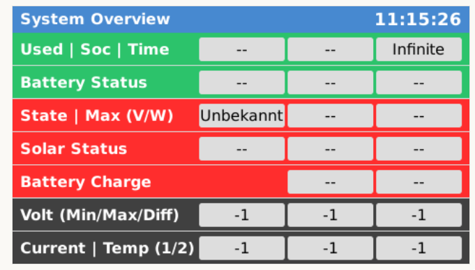
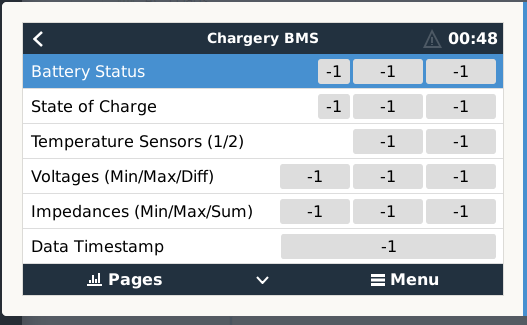
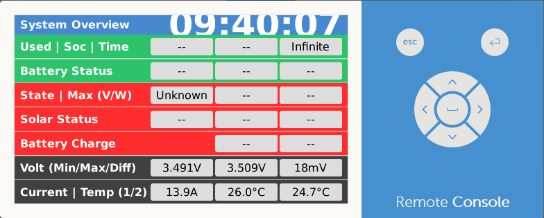
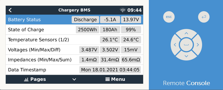
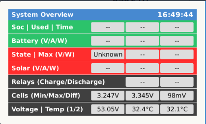
The below screen is missing have you any suggestions as to how to make it appear


2 |3000

Up to 8 attachments (including images) can be used with a maximum of 190.8 MiB each and 286.6 MiB total.

Paul B avatar image
Paul B answered ·

Hi @Tobi17 - would it be posiable to have this program added to Kevin Windrem's SetupHelper program so that it could be blind installed using his setuphelper system - this would make life a lot easyer.

2 |3000

Up to 8 attachments (including images) can be used with a maximum of 190.8 MiB each and 286.6 MiB total.

sgrigor1 avatar image
sgrigor1 answered ·

Hi, can I used this support on standard multiplus II GX?

I have a jkbms and I’d like to integrate it with my multiplus II gx inverter. What should I do?


Thanks


2 |3000

Up to 8 attachments (including images) can be used with a maximum of 190.8 MiB each and 286.6 MiB total.

kevstone122 avatar image
kevstone122 answered ·

Hello Everybody!


Thank to Tobi for this great Github-Articel and integration of Chergery to Victron!

I am also starting to get it run, but one question before.

Is it possible also to control the current-limiting function in the cerbo? So if the Chargery send some difference voltage from 100mV i want to reduce the charge current to prevent overloading.
Is this somehow possible?

Thanks a lot!

Best regards

Kevin

1 comment
2 |3000

Up to 8 attachments (including images) can be used with a maximum of 190.8 MiB each and 286.6 MiB total.

kevstone122 avatar image kevstone122 commented ·
Only with node red possible. All the Chargery values are available in nodered and so everybody can play himself with these values!
0 Likes 0 ·