question

childcarepro avatar image
childcarepro asked

Cerbo GX Tank Sensor Recommendations

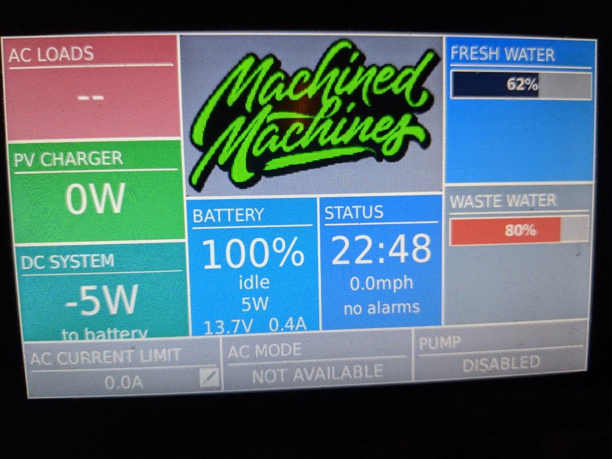
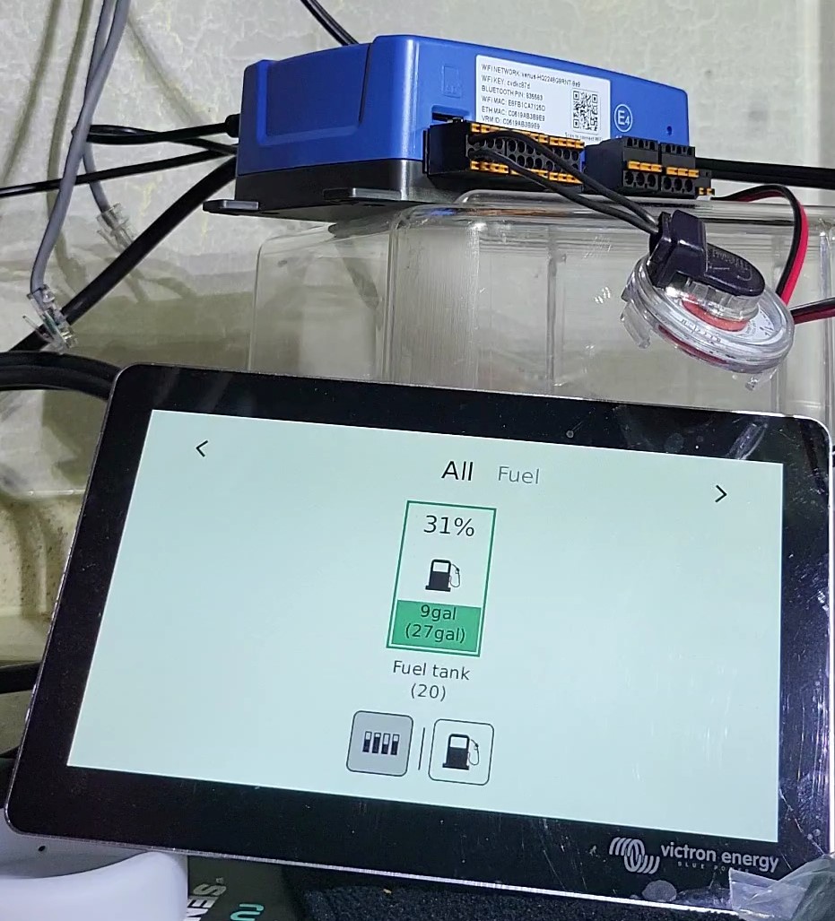
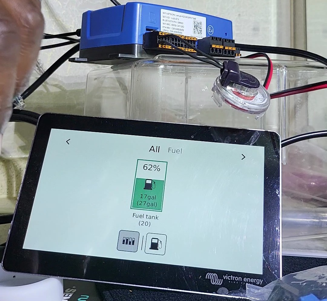
I'm super excited to find that Cerbo GX can monitor my batteries, solar, AND tanks. My stock KIB sensors are nearly useless, reading 2/3 full until gray water starts coming up my drain, signaling 100% full. It's pathetic.

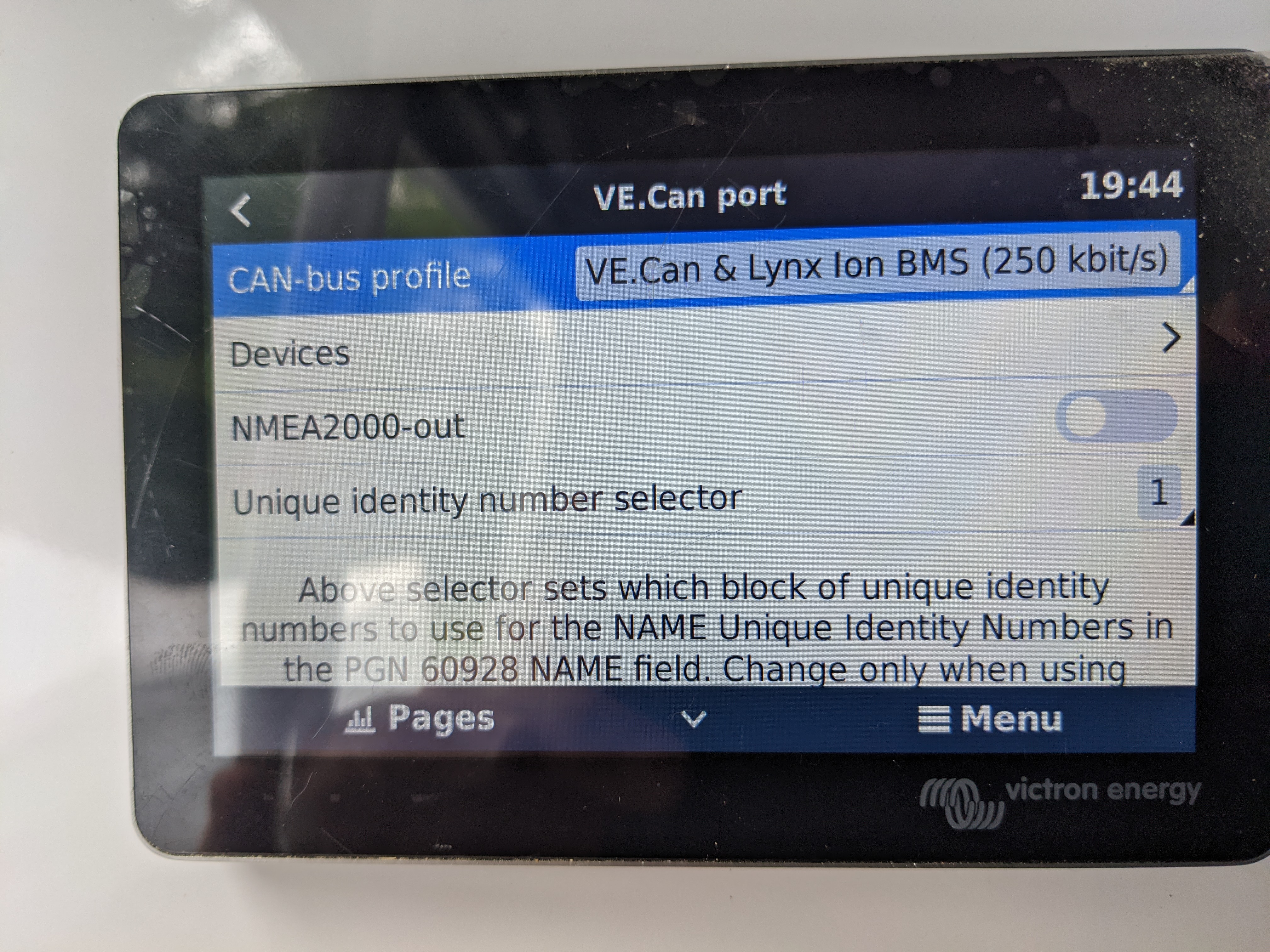
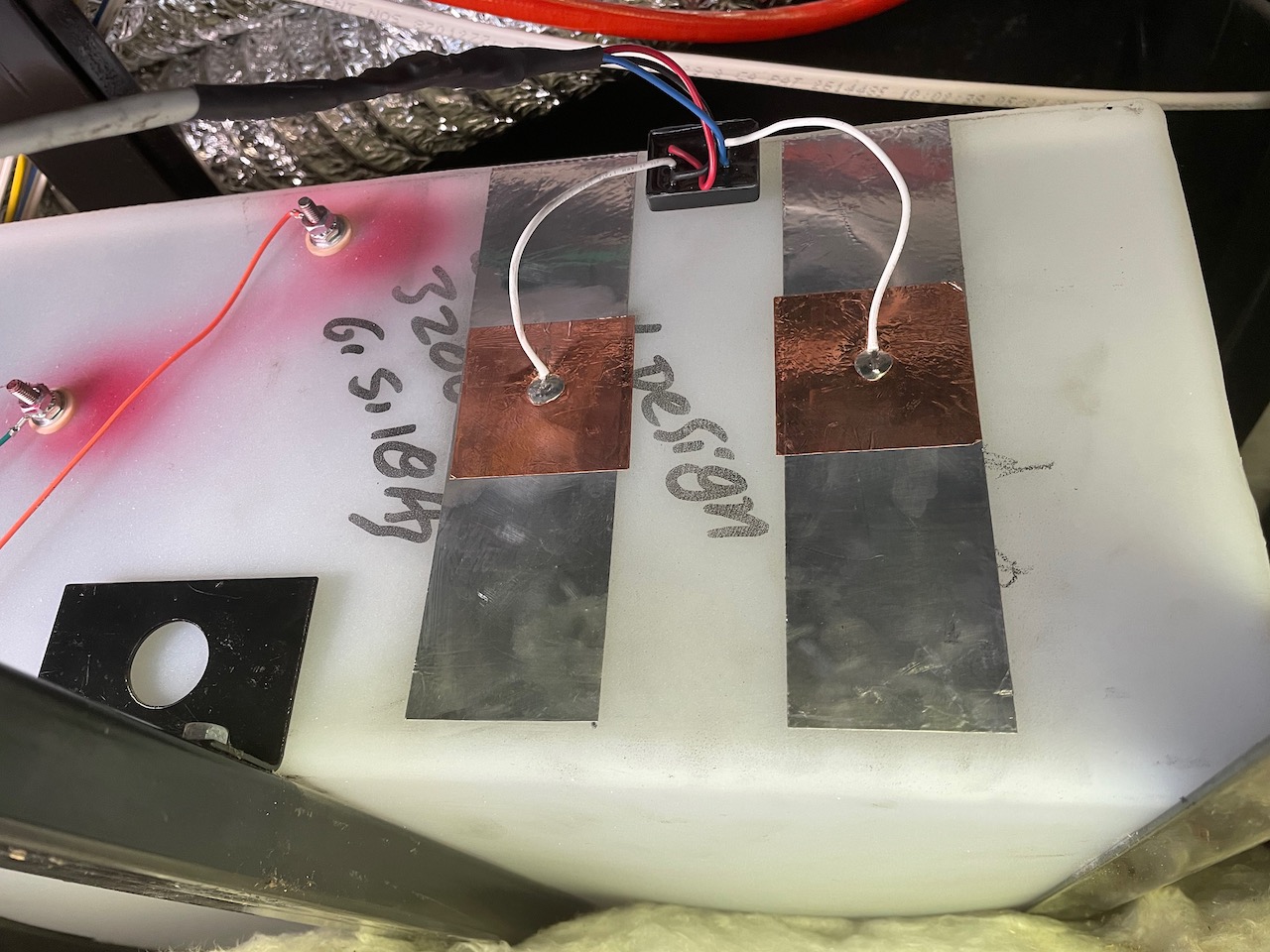
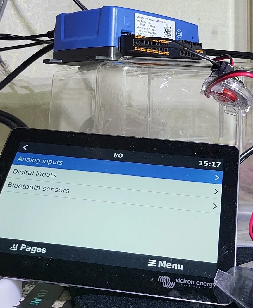
Does anyone know what sensors I can use that will give accurate level readings and work with Cerbo GX / GX Touch? I would like fresh, gray, black, and propane sensors that work with Cerbo GX.

Will this work? Do I really need 4 sensors for just the black tank?!? https://www.etrailer.com/dept-pg-RV_Sewer-pt-Probe_Sensors.aspx

tank monitor
2 |3000

Up to 8 attachments (including images) can be used with a maximum of 190.8 MiB each and 286.6 MiB total.

12 Answers
Kevin Windrem avatar image
Kevin Windrem answered ·

The link in your first post is to the probes your current KIB sensors use. Yes, it takes 4 probes to give you 1/3, 2/3, full readings.

The item in the link in your second post is the type of sender Cerbo is designed to work with. Keep in mind these need to be mounted through a hole in the top of the tank. You'd most likely need to remove the tanks from the RV to mount them.

I've seen some senders that claim you can mount them through the bottom of the tank but can't remember where I saw them.

I used Garnet Instruments SeeLevel in my trailer. These use sensors that stick to the outside of the tank. But they report to their own panel. Garnet does make a NMEA 2000 sensor system that sort-of works with Victron GX systems. I say sort-of because of a limitation in the current code that displays all tanks in the same tile on the display and the device list. I have a "repeater" application that overcomes this limitation. Note that Garnet does not currently sell the N2K system through normal channels. You'd need to contact them directly. It's also a 3-tank system: Black, Gray, Fresh (no Galley or LPG tanks).

The RV-C versions do NOT work with Victron GX devices.

12 comments
2 |3000

Up to 8 attachments (including images) can be used with a maximum of 190.8 MiB each and 286.6 MiB total.

Noah Taylor avatar image Noah Taylor commented ·

I am going to give this a shot. Not a programmer, at least since when I was an 8 year old boy using BASIC on a commodore 64 but I have studied your GitHub write up and think I can pull it off. I ordered the Garnett unit you recommended and the connectors. I will give it a shot this week and write up a quick little summary of my efforts. Thanks Kevin and Ben Brantley for your efforts. Let's hope Victron adds this functionality eventually. Having accurate tank levels is very important to me

And I suspect many others.

0 Likes 0 ·
Kevin Windrem avatar image Kevin Windrem Noah Taylor commented ·

You won't need any programming, but will need to run a script from the command line. There's a link in the readme file that discusses how to enable root access on the GX device. You'll need to "ssh" into the GX device from a computer. I'm on a Mac so use it's unix command line interface Terminal. You can run the setup script from there, but if you are on a Windows machine, you'll need to use a tool like putty to transfer the files, then ssh in to run the script from the GX device.

Good luck and let me know if you need any help getting going.


0 Likes 0 ·
Noah Taylor avatar image Noah Taylor Kevin Windrem commented ·

I read your latest GitHub and noticed the tank repeater was not necessary if I updated the OS to the latest beta OS which I did. When I attached my Seelevel display to the cord I made I am not seeing anything on the Cerbo. I have a feeling I may of made a mistake in the cable.

For reference the 3m connector I purchased was labeled 1-4. Using a standard ethernet patch cable I cut one end off and attached the wires as follows:

1 - white/green

2 - orange

3 - orange/white

4 - green

Got any ideas what might of went wrong here?

0 Likes 0 ·
Kevin Windrem avatar image Kevin Windrem Noah Taylor commented ·

I think your cable wiring is incorrect.

NOTE: SeeLevel tanks are NOT showing up in v2.70~16 released today!!! The services show up in dubs-spy but not in the Mobile Overview or in the Device List.

There are two "standard" ethernet cable wiring arrangements and both have CAN H and CAN L on Wh-Brn and Brn (RJ-45 pins 7 and 8).

V+ (3m pin 1, RJ-45 pin 6) should NOT be connected

This would be either the Gn or Or wire depending on the cable wiring

V- (3m pin 4, RJ-45 pin 3 SHOULD be connected

This would be either the Wh-Gn or Wh-Or wire depending on the cable wiring

Here's a document that shows the two RJ-45 ethernet color coding schemes. You need to inspect the cable to know which was used.

https://incentre.net/ethernet-cable-color-coding-diagram/

Here's the pinout diagram I came up with to show the interconnects between the SeeLevel 3m connector and VE.Can RJ45 (and also the NMES-2000 connector).

CanBus pinouts.pdf

0 Likes 0 ·
canbus-pinouts.pdf (65.7 KiB)
Noah Taylor avatar image Noah Taylor Kevin Windrem commented ·

Ok Thanks a lot Kevin. I will double check and hopefully get this fixed. I will also make sure to not download 2.70-16!

0 Likes 0 ·
Noah Taylor avatar image Noah Taylor Kevin Windrem commented ·

I have a standard Amazon bought 568b ethernet cable. I will attach a picture of the 3m seelevel connection I used. I am pretty sure this is right.

pxl-20210607-201945657.jpg

When connected I see nothing in the tank display or when in the VE. can Port menu there's no Devices listed. Do I need to maybe change the CAN-BUS profile? Any tips will be greatly appreciated.

Noah

pxl-20210607-194431295.jpg

0 Likes 0 ·
Kevin Windrem avatar image Kevin Windrem Noah Taylor commented ·

connection looks correct.

CANbus setup also looks correct.

I had trouble with the 3m connectors on CAT-5 wire. Pry the blue cap off the connector and make sure all wires are actually making connection.

at a command line prompt run can dump any and see if you are getting messages from SeeLevel. You should see 3 messages in approximately 5 seconds but not evenly spaced (that’s ok). There is other CANbus traffic as well.

Make sure the CANbus cable is terminated at both ends. This can get tricky on the SeeLevel end. At least make Sure there’s a VE.Can termination at the Carbon end.


0 Likes 0 ·
Noah Taylor avatar image Noah Taylor Kevin Windrem commented ·

I checked the wires and even stripped them on one try. I am on about my third connector. I ordered four but they are reusable if you pop the top off it seems. I will take another look.

Forgive my ignorance but I don't know what you mean when you say terminate the Canbus cable. Same goes for "VE.Can termination at the Carbon end".


0 Likes 0 ·
Kevin Windrem avatar image Kevin Windrem Noah Taylor commented ·

Dang autocorrect. Last statement should be “Cerbo end.”

CANbus is intended to have 100 ohm resistors at each end of the bus. You should have received two blue RJ-45 terminators with Cerbo. One of these can be used on the Cerbo end of CANbus. The SeeLevel end can’t use the RJ-45 terminators so you need to add a 100 ohm resistor across can H and can L somewhere near the SeeLevel connector. I the cable is short you may be able to get away with only the RJ-45 termination at the Cerbo end.

I did have intermittent connections at the SeeLevel end because the connector they call out is for wires larger than CAT5/6.

3M makes a connector more suited to CAT5/6 wire size. You are more likely to get a better connection than with the one called out by SeeLevel.

https://www.digikey.com/en/products/detail/3m/37104-3101-000-FL100/1238219

You could also splice in larger wires and add the termination resistor at the splice.

0 Likes 0 ·
Noah Taylor avatar image Noah Taylor Kevin Windrem commented ·

Ok copy that. This is what I will try next. I was looking at that Cerbo RJ-45 and wondering what that was for.

Again thanks for the edification and support.

0 Likes 0 ·
jbeck86 avatar image jbeck86 Kevin Windrem commented ·
Why is this termination needed at both ends. We have installed it with only the rj45 termination on the Cerbo Gx and it seems to be working. Is it really necessary to add the resistor on the seelevel end?
0 Likes 0 ·
Kevin Windrem avatar image Kevin Windrem jbeck86 commented ·
Terminations are there to absorb reflections and make data recovery more reliable. You may get away with just one termination or none at all if all connections are short. But for longer interconnects and especially if there are multiple devices connected to the bus, a termination at both ends will be essential.

If it works today you may be OK in the long run or maybe not.

0 Likes 0 ·
machined avatar image
machined answered ·

I ordered these two tank sensors and they work great and were super easy to install. Cerbo looks awesome now with everything.

If you end up getting these then get on the beta releases for firmware because there is a lot of options for dialing in the sensors.


WEMA/KUS Boat Fuel/Water level Tank sensor 11.75" (S5-U300) USA 240-33 Ohm Signal

Kus Boat Black Water Level Sensor / Holding Tank Sending 7.5"/ 240-33 ohm

I bought them at acdcmarineinc.com and you can pick the right length for your tank. These install from the top of the tank and are basically a bobber around a pole and the waste one has a cage around it. You wont use those nubs for the KIB.


cerbo.jpg (248.6 KiB)
8 comments
2 |3000

Up to 8 attachments (including images) can be used with a maximum of 190.8 MiB each and 286.6 MiB total.

childcarepro avatar image childcarepro commented ·

Thanks, glad to know there are sensors known to work! I didn't want to drill, but this sounds like the simplest working solution. Coming from an Airstream with SeeLevel II meters, my wife HATES the KIB style 0, 1/3, 2/3, full sensors. We've had too many unpleasant surprises with fresh water running out, gray water overflowing, etc.

0 Likes 0 ·
Jim avatar image Jim commented ·

Where can I find info on how to connect these to my Cerbo GX? Thanks Jim

0 Likes 0 ·
avalon avatar image avalon commented ·

On your KUS Level Sensor, which wire did you run to the Cerbo? Did you have to go to the KUS sending unit and then to the Cerbo, or just directly to the Cerbo?

0 Likes 0 ·
aopsahl7 avatar image aopsahl7 avalon commented ·
Did you ever get an answer on this?
0 Likes 0 ·
machined avatar image machined avalon commented ·
They just go directly to the cerbo. It was just two wires and you plug them into bottom of the cerbo. The cerbo came with those extra pieces that the wires go into that then plug in the cerbo
0 Likes 0 ·
aopsahl7 avatar image aopsahl7 commented ·
I am in the same boat...But mine don't seem to be working. I ordered the KUS senders and plugged them directly into the tank level ports on the CERBO GX. But it is saying not connected.


Trying to understand if I can connect them directly or I need to purchase the CAN BUS adapter...

0 Likes 0 ·
Kevin Windrem avatar image Kevin Windrem aopsahl7 commented ·
It depends on what you bought. KUS has resistive senders that would be compatible with Cerbo tank inputs, capacitive senders that are voltage or current output and would probably be compatible with the GX Tank 140, or CANbus senders. You'll need to contact the manufacturer with the model you purchased to find out with is needed.
0 Likes 0 ·
machined avatar image machined aopsahl7 commented ·
You might have to play with the settings in the cerbo. I think the basic settings needed to be changed to get it to work.
0 Likes 0 ·
mcornforth avatar image
mcornforth answered ·

Just ordered some differential pressure sensors from Safiery. They look to be robust, accurate, and require no new holes cut in my tank. I believe I saw someone do a DIY version of this with an available automotive pressure sensor, but I decided to pay a little to have someone I can call if I have issues. They'r nice bloaks and do some really awesome work. These sensors do need the GX Tank 140 as they are voltage based sensors.


Here is a link to all of their tank sensors and info on them: https://www.safiery.com/tanks

2 comments
2 |3000

Up to 8 attachments (including images) can be used with a maximum of 190.8 MiB each and 286.6 MiB total.

eric-thomas avatar image eric-thomas commented ·
Have you installed these yet? Where did you use them?
0 Likes 0 ·
epiphvany avatar image epiphvany commented ·
I'm also interested to see if these work. So are you saying you have to purchase the GX Tank 140 for them to work? They don't plug directly into the Cerbo? Thanks
0 Likes 0 ·
childcarepro avatar image
childcarepro answered ·

Would this work? https://www.ebay.com/itm/293486607587 These say 0-190 ohm sending units, available in 150-600mm, and I just need to know my tank depth?

1 comment
2 |3000

Up to 8 attachments (including images) can be used with a maximum of 190.8 MiB each and 286.6 MiB total.

dunnp avatar image dunnp commented ·

Be wary of this type of sender - very crude resolution. The one I bought only had 4 levels - and not very linear either. They are just reed switches that switch in a resistor ladder.

0 Likes 0 ·
childcarepro avatar image
childcarepro answered ·

Thank you, @Kevin Windrem, that was helpful. Haha I guess now it makes sense, one sensor for each "level" it detects. But I thought those sensors used 4 holes in the side of a tank; I suppose the ones I linked to are more accurate than the side holes?

If you have to remove the tanks, that's not easy. And not an option for the propane tank. :( I would love to use SeeLevel stick-on sensors if they would report resistance numbers that could be read by the Cerbo GX.

9 comments
2 |3000

Up to 8 attachments (including images) can be used with a maximum of 190.8 MiB each and 286.6 MiB total.

Kevin Windrem avatar image Kevin Windrem commented ·

The SeeLevel sensors won't connect directly to Cerbo. The sensors connect to their control panel then on to Cerbo. The entire system is about $350 for 3 tanks -- no propane on this model.

You need to contact Garnet Instruments and ask if you can purchase a model 709-N2K_NLP. It's an OEM model they have sold to end users on a few occasions.

You then need to install and run my tank repeater software that overcomes the one tank per sensor limit for N2K devices.

You would also need to make up a cable to go from the Cerbo GX to the SeeLevel control panel. More details and the tank repeater software is available here. Look it over to see if it's something you are interested in and can handle. Note that Victron does have plans to update their NMEA2000 tank sensor software in a future release but it probably won't make it into v2.60.

https://github.com/kwindrem/TankRepeater

BTW, some permanently mounted propane tanks come with a built-in sender. It is unlikely you'll find senders on portable (20-30 pound) propane tanks. But the good news is that if you have such a tank, the sender is resistive and should interface directly with Cerbo GX.

0 Likes 0 ·
childcarepro avatar image childcarepro Kevin Windrem commented ·

@Kevin Windrem, you're awesome. Thanks for sharing your work with the community! I've checked out your GitHub project page but haven't gotten any further. I'm no Linux expert, but I've been known to type in some commands from time to time to get stuff done. :)

OTOH, since we're not sure whether Victron will adopt RV-C or NMEA2000, maybe I'm better off living with my crappy senders for now until plans solidify? I've heard of people trying to use the 4-level KIB-style senders with the Simarine Pico, so maybe I can see if Cerbo GX can make sense of these readings until we get better sensors?

The other option is to insert 0-190 ohm senders. More labor, but more precise resolution, as we would get continuous resistance readings rather than a quantum reading every 3/8". Correct?

Regarding propane, my little Winnie does have a sender on it, my One Place monitor reports it in 25% increments.

0 Likes 0 ·
Kevin Windrem avatar image Kevin Windrem childcarepro commented ·

It appears the Pico system uses resistance or voltage sensors and probably exhibit the same issues trying to use the KIB probes as Cerbo would. That is unless Pico has a converter module.

I'm using SeeLevel JS senders on my tanks because they are 6" and 7" tall. I'm seeing 1-2% changes in levels. According to Garnet's documentation resolution should be between 1/4" and 1/2" which is about 4% on my JS sender at 7".

A resistive sender might provide more resolution but not convinced it would be necessary.

As I mentioned previously, there are senders that can mount into a hole in the bottom of the tank but I'd worry about leakage.

0 Likes 0 ·
childcarepro avatar image childcarepro Kevin Windrem commented ·

@Kevin Windrem, have you heard of SCAD or TankEdge external sensor strips? I don't know what these sensors output, resistance, voltage, or digital data. But someone mentioned it has one extra wire than their existing tank sensors. https://tankedge.com/accessories.html https://www.defender.com/product.jsp?id=1345546

Do you think the Cerbo GX can connect to these sensors directly? The gold standard would be:

1) high resolution
2) high accuracy
3) externally mounted (non-fouling)
4) direct connecting (no interfacing/bridging)

Thank you.

1 Like 1 ·
scott-2 avatar image scott-2 childcarepro commented ·
Ever get the SCAD sensor hooked up?
0 Likes 0 ·
childcarepro avatar image childcarepro Kevin Windrem commented ·

Thanks, @Kevin Windrem. SeeLevel is 99% the way to go... wondering whether to wait to see if Victron chooses RV-C or NMEA2000. Sounds like since NMEA2000 is farther along in development, does that make it more likely to be adopted by Victron?

It's reassuring to hear the resolution is higher than 3/8"!

If I went the 709-N2K_NLP route, I imagine it would likely continue to work even after Victron adds support for NMEA2000 natively, correct?

0 Likes 0 ·
Kevin Windrem avatar image Kevin Windrem childcarepro commented ·

I think N2K is the way to go. RV-C may or may not be implemented in Venus but right now it is not.

You will need to contact Garnet Instruments to see if they are willing to send you the N2K version. It isn't in their catalog and is an OEM for some RV manufacturer. It took a while to get mine but that all depends on their production cycle.

There are other N2K tank systems.They *should* work with my tank repeater but I have no experience with them.

Venus currently supports N2K tank systems that report only a single tank. If an N2K system reports multiple tanks, Venus combines all the tanks in one display so the values and fluid type keeps changing. My tank repeater sorts that out and provides stable displays for each fluid type.

Again, the link to that software is:

https://github.com/kwindrem/TankRepeater

I've made it pretty easy to install (in my humble opinion) and will be here to help if you have issues.

There is no reason a Victron native solution wouldn't work with the SeeLevel N2K system. In fact, they have a SeeLevel system in house for development and testing. You would of course at that time want to disable the repeater. But you may wish to keep some or all of the modifications I've made to the Mobile Overview page. My revised tank tile compresses vertically to support additional tanks. Plus I have a completely new layout for the Mobile Overview page. If you like lots of numbers you may like it.

I found a little information on your One Place sensors: They *may* be capacitive from the testing instructions, but would be sending proprietary information to the One Place panel. They still function like the KIB probe types with empty, 1/3, 2/3, full resolution. The LP sender is 0 ohms empty and 90 ohms full but no indication of the number of steps in between. This range does not conform to either the European 0-180 ohm or the US 240-30 ohm standards (empty-full). So your sender may not interface with Cerbo with v 2.54 software. v2.60 will have adjustments that *may* accommodate the 90 ohms full. I have no analog inputs on my CCGX but you could check this now if you want to update to the latest release candidate. New setup menus permit switching to a "Custom" standard then adjust empty and full resistances.

0 Likes 0 ·
Kevin Windrem avatar image Kevin Windrem Kevin Windrem commented ·

Here's a rewrite to the SeeLevel tank repeater:

https://github.com/kwindrem/TankRepeater

0 Likes 0 ·
Noah Taylor avatar image Noah Taylor Kevin Windrem commented ·

Well this is pretty perfect timing. I hope to be connecting all my See level components and the Victron stuff very soon.

0 Likes 0 ·
childcarepro avatar image
childcarepro answered ·

OMG people, I think I'm onto something here. I found this document at TankEdge: https://tankedge.com/downloads/Moda_Sensor_Testing_Procedures.pdf

It states to test the Moda sensor: "…check the voltage coming out of the sensor across the blue to black wires at the sensor. This also needs to be done while the voltage is being sent down to the sensor just as above. This reading will vary depending on the liquid level in the tank. It should not be over 5 volts but could be very small, even a fraction of a volt with low levels."

So the output of the Moda sensor is 0-5V, with 12VDC input. But I just read the Cerbo GX manual and it states it only supports VE.Can, NMEA2000, and analog resistive sensors. Sadly, there is no mention of voltage sensors.

The extra wire I mentioned in a previous post is simply a black ground wire.

It would be so amazing if this could work, but it appears the TankEdge system bucks the trend of all other tank sensors in being voltage senders rather than resistive.

15 comments
2 |3000

Up to 8 attachments (including images) can be used with a maximum of 190.8 MiB each and 286.6 MiB total.

Kevin Windrem avatar image Kevin Windrem commented ·

It all depends on the output impedance of the sender. I saw somewhere that the pullup inside Venus devices is 680 ohms to +5 volts. That's 8 mA to reach 0 volts. Plus, it also requires Cerbo's new calibration (part of v 2.60 when it's released) to accommodate the voltage range of this sender.

But it's worth someone experimenting with them. If it's close, Victron could possibly tweak their software to support them.

0 Likes 0 ·
childcarepro avatar image childcarepro Kevin Windrem commented ·

I emailed Tech-Edge Manufacturing asking whether it sent voltage and resistance, the response:

"I’m sorry. Our sensors are capacitive sensing only sending voltage."

I'm willing to try it if you still think it's worth a try. But at this point I have to admit SeeLevel's NMEA2000 might be the best option. I wanted a direct sensor solution for finer resolution and fewer potential points of failure, plus I didn't want to have to hack my Cerbo GX right out of the box.

0 Likes 0 ·
Kevin Windrem avatar image Kevin Windrem childcarepro commented ·

There are too many unknowns at this point to be confident these senders will work directly with Cerbo.

What is the voltage range Cerbo can tolerate on it's tank inputs? A 180 ohm sender would reach approximately 1 volt, so these senders would produce approximately 5 times that voltage which might be outside the range of the calculations currently used.

Can the sender drive a 680 ohm load to +5 volts directly?

A buffer circuit would be fairly easy to design that could interface the two.

0 Likes 0 ·
childcarepro avatar image childcarepro Kevin Windrem commented ·

One of us clearly knows what he's talking about... and it isn't me. Hahaha So I'm educating myself... resistive senders have variable resistance that causes variable voltage outputs; capacitive senders output variable voltages.

1. I'm willing to test, but I'm clearly in over my head as far as electronics know-how;

2. As you note, 0-5V is a much wider range than 0-1V; I'm wondering if the Cerbo GX's circuitry even supports 5V or whether it will clip at 1V? If it can handle up to 5V, then simply calibrating could fix this discrepancy?

3. A bigger problem is I'm under the impression capacitive sensors use alternating current; will Cerbo GX have a problem with that?

1 Like 1 ·
Kevin Windrem avatar image Kevin Windrem childcarepro commented ·

Resistive senders are simply a variable resistance. That resistance works against the pull-up resister inside the display device to produce a voltage.

The senders you are looking at have a module that reads capacitance between the two strips stuck to the side of the tank. The module converts that to a voltage that is sent to the display unit. I'm sure this will be a DC voltage. But you are right to assume the capacitive level detection mechanism will use an AC voltage, probably fairly high frequency.

The module at the tank will have a finite output resistance. If that's low enough it could work predictably against the 680 ohm pull-up inside Cerbo. If not, the pull-up will offset the voltage the module outputs. In the limit, the 680 ohm resister could overwhelm the module and voltage would end up at 5 volts regardless of the tank's level.

At this point, we just don't know how these two devices will interact.

If the sender's module can provide a usable voltage swing against the 680 ohm pull-up in Cerbo AND Cerbo can be adjusted to accept this voltage swing for empty-full levels then you are golden. Cerbo's adjustments (part of v2.60) are calibrated in resistance so my best guess is it wouldn't be able to handle the full 5 volts of a full tank. That would equate to an infinite sender resistance.

Some form of buffering between each tank module and the Cerbo input will most likely be needed.

I don't have a Venus device with tank inputs so can't do any testing. I also can't get my CCGX to think it has tank inputs so I don't know what the sender resistance adjustment range is. You could check this out by installing the latest Venus release candidate (v2.60~33 at this time).

2 Likes 2 ·
childcarepro avatar image childcarepro Kevin Windrem commented ·

Wow, thank you, @Kevin Windrem. That was very helpful.

I have reached out to Tech-Edge Mfg (tankedge.com), and they said if I wanted to experiment, their engineers would be able to answer any questions I had. So I think I'll order my Victron setup including Cerbo GX and one Tech-Edge MODA sensor, and we'll see how that experiment goes!

Tech-Edge also makes a regulator for the MODA sensor that raises it to 10V for an older control panel, so I asked if we could lower it to 1V for the Cerbo GX.

Fingers crossed!

1 Like 1 ·
childcarepro avatar image childcarepro childcarepro commented ·

OK correction, the regulator brings DOWN the 12V coming from other control panels TO the 10V the MODA requires. I talked to Tonya at Tech-Edge today who had discussed with engineers. So it takes 10V input and outputs 0-5V, but usually empty is slightly above 0 and full is around 3V. She said we could use a resistor to reduce the voltage to 0-1V, but also was concerned about what voltage Cerbo GX outputs TO the senders, as the MODA expects 10V but will work down to a lower voltage but will not function below a certain voltage. She will check with the engineers.

If they can make a version of the MODA that functions within the Cerbo GX's parameters, or at least come up with a mod for it, this could be an amazing solution for Cerbo/Venus GX users.

1 Like 1 ·
Kevin Windrem avatar image Kevin Windrem childcarepro commented ·

A resistor to drop voltage probably won't work since Venus devices are pulling UP to +5 volts on each sender line with 680 ohms.

3 volts is more in the ballpark but haven't heard from anyone at Victron what voltages they can deal with, or put another way, what resistance ranges their new software can be set to. Resistance set in the menus will convert to a voltage when the 680 ohm pull-up is factored in.

Not sure if the pull-up can be turned off which would allow the input to be used as a direct voltage input and more likely to work with the MODA senders.

It sounds like the widget Tech-Edge has to reduce 12 volts to 10 volts would be required since a typical RV would have a 12 volt electrical system. Venus devices would not provide power specific for the senders.

1 Like 1 ·
childcarepro avatar image childcarepro Kevin Windrem commented ·

@Kevin WindremDo you have any more information since v2.60 was released? I have decided to order my tester Moda sensor to try with my Cerbo GX now that v2.60 has been released.

I have yet to power on my Cerbo GX to my multimeter to see what its output voltage is. I have LiFePO4 DIY cells (4S and 8S setups) but have not decided on which BMS to use, so no power for the Cerbo unless I use another 12V LiIon battery pack with barrel connectors and strip the wires.

I really love what you've done with connecting the SeeLevel II NMEA version, but I'm trying to keep the complexity to a minimum by directly wiring in senders rather than having a whole other system plus an interface between Venus OS and SeeLevel II's system plus any potential funkiness in the NMEA2000 implementations of the two companies.

1 Like 1 ·
Kevin Windrem avatar image Kevin Windrem childcarepro commented ·

Nothing more here on my end.

0 Likes 0 ·
green-monster avatar image green-monster childcarepro commented ·

I installed a Tech Edge system in a prior RV and it worked great, would love to find out if their sensors could be used with the Venus GX for my new RV. Have you found out any more information?

1 Like 1 ·
childcarepro avatar image childcarepro green-monster commented ·

@Green Monster I'm about to order a sample Moda sensor or a pack of sensors and try plugging them in to see if it works.

I am FED UP with the nearly useless, empty-1/3-2/3-full KIB-style sensors. I've already run out of fresh water showing 1/4 full, overflowed my fresh tank when sensor shows 3/4 full, had gray water back up into my shower pan showing 2/3 full... twice...

0 Likes 0 ·
jetalkington avatar image jetalkington childcarepro commented ·

I am following this conversation as I have a Toyota Sunrader I am rehabbing and want to have a full system monitor in place. I have been looking at Simarine and Cerbo GX. But, I went Victron on all my solar and think the Cerbo would be better fit. The tank and LPG monitoring is a big deal in a motorhome. Please keep posting back any results you get.


0 Likes 0 ·
woodbri avatar image woodbri childcarepro commented ·

@childcarepro did you get and try the Moda Sensors with the CerboGX and/or the new GX Tank 140?

0 Likes 0 ·
childcarepro avatar image childcarepro woodbri commented ·

Sadly, it's still sitting in my garage. All of it, my whole solar setup and Moda sensor.

1 Like 1 ·
woodbri avatar image
woodbri answered ·

I emailed TankEdge about their Moda sensors and got this response "

The Moda sensors work on voltage. 0 to 5 Volts with full usually being somewhere around 3 volts. Our panel sends 10 volts down to the sensor on the blue wire and that voltage comes back as variable voltage on the red wire between 0 and 5 (like I said with full being usually around 3) That amount will vary greatly with each tank and the foil set-up which is why our panel is calibrated to the tank. I'm not sure if your GX Tank 140 adapter will work for this type of set-up or not. We do not have any adapters for that system. Let me know if you have any other questions.

Thank you,
Tonya Adams
541-610-0401 ∙ www.tankedge.com

"

So this sounds like it would be compatible with the GX Tank 140. I would be interested in knowing if anyoneelse has had success with these on a GX Tank 140. The Moda sensor cost $35/tank https://tankedge.com/accessories.html

11 comments
2 |3000

Up to 8 attachments (including images) can be used with a maximum of 190.8 MiB each and 286.6 MiB total.

kamflyer avatar image kamflyer commented ·

So I have been playing with a MODA sensor from Tankedge today and am happy to say it seems to be working fairly well.

I have a 35 gallon transfer tank which measures 9" high that I am using as a test bed before tearing into the belly of my beast. I set up the sensor initially using 3" foil strips 2" apart and 1/2" from the top and bottom of the tank. That gave me 24 sq in per strip or 48 sq in total. This worked not too bad but I found the sensor peaked at about 3.6V while still at only about 80% capacity. After a bit of trial and error I settled on 2.5" strips, 2" apart and stopping about 1/4" from the top and bottom edges. This gives me a range of 0.7V for empty to 3.2V for full.

I have it interfaced to the GX Tank 140 using the GX Tank's 24V output and dropping the voltage at the sensor to 12V using a small regulator.

Even though my test tank is rectangular, one thing I have found is that output isn't exactly linear. I had to set it up using a custom shape. The voltage changes much quicker at the bottom of the tank and slows down towards the top.

I will play a bit more before settling on a final solution for my rig but so far my initial tests are quite positive.


2 Likes 2 ·
orion60 avatar image orion60 kamflyer commented ·

Thanks for the update, Kamflyer. I have a Tankedge system and a 9" high tank as well. Would love to interface it with my Cerbo, so I am very interested in seeing how your experiments pan out. I'm waiting to bite the bullet on the Tank 140 until I see someone successfully interface the MODA sensor to the 140. Sounds like you are on your way, so please keep us posted! And again, thanks for your efforts.

0 Likes 0 ·
derrick thomas avatar image derrick thomas kamflyer commented ·
Are you still having good results with the moda sensors and the tank 140? I'm getting ready to do a complete equipment swap from Magnum over to Victron and would sure like to be able to use my existing moda sensors.


What method are you using to supply power to the sensors and at what voltage? It would be great if I could just supply power from a single external source to all 4 sensors and just use the ground and input terminals on the tank 140.


Thanks a bunch!

0 Likes 0 ·
kamflyer avatar image kamflyer derrick thomas commented ·

Good timing Derrick! I just today installed the sensor on my fresh tank in the RV.

So far the results are very positive although I haven't been able to test the linearity of it yet. It did seem fairly linear while filling the tank though.

The 83 gal tank in my rig is 7 1/2" deep so I wound up using 2" strips (1 7/8" actually), 7 1/4" long and spaced about 1 3/4" apart. The sensor is fed 24V from the GX Tank 140 and regulated to 12V using a small 12V switching regulator. Tankedge doc indicates 12V is OK as long as it is regulated.

This gave me an empty value of 0.4V and a full value of 3.2 to 3.3V.

It's kinda hard to see in the photo but the bottom of the tank has quite a rounded edge so the tape stops just short of the curve.

img-7292.jpeg

The regulator is encased in that piece of heat shrink at the top of the photo. Got them off Amazon.

I was a bit concerned about the proximity of the steel tank supports but they don't seem to bother it.

Once I have had a bit more time I will document it a bit better.

1 Like 1 ·
img-7292.jpeg (291.9 KiB)
derrick thomas avatar image derrick thomas kamflyer commented ·
I tried the moda sensors since I already had them installed. They did work but they were not consistent at all. I ended up going with pressure transducers and am very happy with them. They are extremely accurate from full all the way down to empty.
0 Likes 0 ·
eric-thomas avatar image eric-thomas commented ·
Have you tried these out?
0 Likes 0 ·
Kevin Windrem avatar image Kevin Windrem commented ·

I tried out the Moda sensors on the GX Tank 140 and they did not work. The sensor's output impedance is extremely high and even the high resistance pull-up in the GX Tank pulls the sensor output up to an unusable level. No variation in the output with tank level at all.

Also, the Moda sensors need a stable power source. Connecting to the battery won't work as the output is proportional to battery voltage.

It might be possible to buffer the Moda sensor and provide a regulated supply but have not tried it.

0 Likes 0 ·
childcarepro avatar image childcarepro Kevin Windrem commented ·

@Kevin Windrem You're awesome. So here we are 15 months since I started this thread, you've done amazing work and even humored my TankEdge Moda sensor idea, Victron has released another tank monitoring accessory… but we still seem to be at the same place: the SeeLevel II NMEA 2000 with your software still seems to be the best solution. Victron is not going to make my dream of a simple way to directly connect tank senders a reality? I can't be the only one on the planet who wants an all-in-one RV monitoring system that works.

Yet you tease with, "All this IS possible." To quote from Dumb and Dumber, "So you're saying there's a chance!"

What do you think it would take to get the Moda sensors to work? I want the simplest solution possible to reduce failure points, but solid state components would last forever barring heat damage, so electronic components that can tweak the outputs sounds promising.

It would be amazing if TankEdge were interested in modifying their electronics to work with the Cerbo GX directly (converting their capacitive readings into impedance values). Maybe now that they've had several people email them? Do we need an email campaign? A group buy? What do you all say?

1 Like 1 ·
itgoes211 avatar image itgoes211 Kevin Windrem commented ·
Would you not want to use voltage instead of impedance on the Tank 140 to measure tank level?

Also you could use a voltage regulator to get the constant 10 volts. Tech-Edge even sells one. Toward the bottom of their accessories page.


0 Likes 0 ·
Kevin Windrem avatar image Kevin Windrem itgoes211 commented ·
My tests with the GX Tank WERE in voltage mode.

Yes, a 10 volt regulator would be easy of other issues didn't exist.

I looked into an op-amp based buffer but would also need a positive and also negative power supply because the sensor voltage goes to zero.

All this IS possible.

0 Likes 0 ·
itgoes211 avatar image itgoes211 Kevin Windrem commented ·

Gotcha. Thanks for the info. I'm looking for something to put in my RV.

0 Likes 0 ·
childcarepro avatar image
childcarepro answered ·

Has anyone tried SSI FluidTrac 2-wire sensors? https://kodiakcontrols.com/wp-content/uploads/2016/10/ssi_fluidtrac2_sensor.pdf

It seems too good to be true: a non-contact sender with resistive outputs (does require a hole at the top, emulates 30-240 ohm output). I would take a single hole at the top over a float tube sticking into the fluids (gag)! Plus it has as range of 2 to 32", so I wouldn't need to fret over getting the exact height of the tube right.

Theoretically this should plug-and-play with the Cerbo GX? I just need to pick a direction that works.

Also, just to clarify, the Winnebago's built-in propane level sender should be a resistive sender and also be plug-and-play with Cerbo GX? (After calibration, of course)

Update: I can't seem to find any web listings or pricing for this product, which is concerning. I only see links to that PDF document or HTML description pages, no actual product listings.

2 |3000

Up to 8 attachments (including images) can be used with a maximum of 190.8 MiB each and 286.6 MiB total.

Roger Parker avatar image
Roger Parker answered ·

I found where you can buy the FluidTrac 2 wire sensors at US Marine Products. I would like to see someone who knows what they're doing test these.

https://www.usmarineproducts.com/Ultrasonic-Water-Senders-p/ultrasonic-sender-water.htm

2 |3000

Up to 8 attachments (including images) can be used with a maximum of 190.8 MiB each and 286.6 MiB total.

david-bradsher avatar image
david-bradsher answered ·

Scad technology uses Moda sensors and is working on a nmea 2000 solution. Should be out in summer2022

2 |3000

Up to 8 attachments (including images) can be used with a maximum of 190.8 MiB each and 286.6 MiB total.

-chris avatar image
-chris answered ·

A bit late to the game, but I wrote a quick page with my solution, a pressure voltage sensor, and it works great. You will need the GX Tank 140 to support this "voltage" sensor.

https://www.fipfop.com/van/splumbing/splumbing.html

2 |3000

Up to 8 attachments (including images) can be used with a maximum of 190.8 MiB each and 286.6 MiB total.

vick-da-aerbus avatar image
vick-da-aerbus answered ·

Not sure where this fits in the conversation. I had a problem with the Cerbo GX. I lost the analog input. I have a replacement and went to set it up. One of the first things I looked at was the availability of analog input. I purchased a new Manchester tank sender. I hooked up the two wires and placed them in tank 1. I turned on tank input and it popped up just fine. To test the gauge, I used a magnet to change the gauge quantity. The Cerbo responded with a short delay.

Delightful.

I setup a custom Ohm setting -- 0 = empty. 90 = full. I set the gallons to 27 gallons based on the tank quantity (change later to 29). I didn't change the dimensions; save for later. I again changed the gauge quantity but using a magnet. The Cerbo Gx accepted the change showing a slight delay as I emptied and filled the LP tank.

Takeaway.

1. Make sure Tank setting is off. Not sure if this means anything, but if I plug in another analog input, I'll make sure the setting is off first.

2. The 0-90 Ohm tank sender carries no voltage.

3. I tested the sender with its short cable. I plan on running wires without connecting to ground from propane tank to Cerbo: two wires direct from sender to Cerbo tank input. This adds a little bit of work but using a ground seems to be asking for trouble until Victron or someone smart can ensure how the Cerbo Gx handles voltage on the tank input.


videocapture-20230531-213313.jpg videocapture-20230531-213459.jpg videocapture-20230531-213449.jpg


2 |3000

Up to 8 attachments (including images) can be used with a maximum of 190.8 MiB each and 286.6 MiB total.