question

ciki avatar image
ciki asked

Using the ColorControl GX in a DC-only system and UI display

I have no experience with the CCGX and would appreciate comments on this configuration.

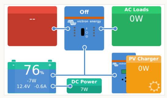
Looking at documents on the www, it seems that the CCGX UI main display has one predetermined way of displaying the system (maybe depending on what VE.BUS device is connected) The upper part shows the AC input / output and the lower part shows the DC input / output , battery and charging/discharging plus PV inputs.
I have a non-Victron battery charger and a nonVictron inverter, which I can not connect to the CCGX. Still I want to use the CCGX to collect infos on the generated 24V (300W water turbine) and the 24V power consumed by the nonVictron 230V inverter, using 2 BMV700 with their corresponding shunts. A BMV703 will be used to monitor the battery (SOC). Also three Solar MPPTs will be connected to the CCGX. The idea is to have a central information display for the relevant parts of the system (24V) and to use the CCGX with a GSM module to connect to the Victron portal (VRM). I will use the three VE.direct sockets on the CCGX for the three BMVs. For the Solar MPPTs I will use VE.direct to USB converter cables and connect all three, through a (powered) switch to the USB socket on the CCGX. I am somewhat confused on what exactly will I be able to display on the CCGX screens. The most important question that I have, is whether I will be able to see the relevant data for all attached VE.direct devices individually, in any available menus on the CCGX (and VRM)? Is the data for the 3 Solar MPPTs shown individualy, or consolidated to a single value?Thanks.

CCGX Color ControlVE.Directdc system
2 |3000

Up to 8 attachments (including images) can be used with a maximum of 190.8 MiB each and 286.6 MiB total.

3 Answers
David avatar image
David answered ·

The Graphical screen on the CCGX shows the "system" information.

What this means for your setup is that the Solar part will be the overall Yield (in Watts) of all the MPPT Controllers.

The Battery and DC Power information will come from only one Battery Monitor source - you will have to choose in the setup which BMV you want that to be.

In the Device lists, you can see the individual devices and the values at that moment. Below is my setup where I have two MPPTs (both off currently), and two BMVs - each connected to a different Source.

And in the System Setup, you need to chose what Battery Monitor source you want to have as the "System" Monitor (as per the screen below. It is not that easy to tell them apart!)

And the graphical screen only shows that Monitors data in the Battery/DC Load section


In VRM, in the 'Advanced' tab, you can see all the data from all the different devices individually. That is likely your best source of info to view?


1591975505175.png (53.9 KiB)
1591975882923.png (43.0 KiB)
1591976198520.png (38.9 KiB)
2 |3000

Up to 8 attachments (including images) can be used with a maximum of 190.8 MiB each and 286.6 MiB total.

jwfrary avatar image
jwfrary answered ·

hi,


there won't be a huge amount on the screen, you will have just a battery and a green box labeled dc power and another labeled pv charger.

top displays will just say zero and not connected.

you may be better to save some money and use a venus gx and access the data logged on VRM.

with two bmv on the bank for those two sources, the data will all look a little funny as they are meant for counting power in and out rather than metering.

if this is what your after you would be better installing dc meters. (or using victron inverter equipment.)


2 comments
2 |3000

Up to 8 attachments (including images) can be used with a maximum of 190.8 MiB each and 286.6 MiB total.

ciki avatar image ciki jwfrary commented ·

Thank you Jwfrary

Agree. Even if "misusing" the BMW as power meters and having an very limited system overview on the CCGX , the value I hope to get is:

- ability to view the system status from a remote location via VRM (which I could not achieve, by installing DC meters locally).

- display locally as well as over VRM the power feed from the 3 MPPTs.

- in the future I will replace the non-Victron inverter with a Victron Multiplus.

As mentioned, the primary purpose is to have a central system to view and collect data, as well as send it to the VRM. I was unable to find examples for similar DC-only configurations on the www.

Can you confirm that on the CCGX (and VRM), I would be able to display somehow (maybe on the device list), the present power values (Amps or Watts) for the three MPPTs as well as the the ones measured by the BMV shunts?


0 Likes 0 ·
jwfrary avatar image
jwfrary answered ·

Yes it will, just won’t be very smooth but I can see what your trying to do.

Obviously you will have losses with the shunts and the SOC figures won’t work on either as each bmv can’t account for all the power leaving and entering the battery.

You might want to look at mod bus meters, not much of an expert with that but could work for your needs though at a quick look I think they only support AC ones but could be worth looking into.

Then you can have your single bmv monitoring loads and charging and your modbus meter giving you a figure for the water turbine, you can then simply do the math afterwards.

I guss with the multiple bmv you’ll have to turn everything off except the consumption for it to work without alarms and that sort of thing.


2 |3000

Up to 8 attachments (including images) can be used with a maximum of 190.8 MiB each and 286.6 MiB total.

Related Resources

CCGX Product Manual

CCGX Product page

Additional resources still need to be added for this topic

VE.Direct protocol FAQ