question

Paul Skelly avatar image
Paul Skelly asked

BP 220 remote control using switched battery negative

Hi,

I have an issue with an RV that I am hoping someone may assist. I want the relay in the BMV712 to isolate the batteries at XX% SOC and have done this for the BP 220 but most of the load in the RV is fed of the same wires as a Victron solar MPPT. I use the BMV networking to supply the MPPT with the battery Voltage and Temperature.

The cut-down circuit below is some of the existing RV electrics and there is an issues I am trying to overcome.

The makers or the RV saved some dollars by only running one pair of cables from the batteries to the cupboard over the sink and there is no way to get more cables inside the walls - well without removing the cladding.

In the cupboard is a Victron MPPT and the battery supply terminals are paralleled across to a Voltech Battery Protector so I cannot use the Victron BP 200 to protect the battery - I would get reverse current through the BP 220 when the MPPT is charging. All of the fuses that supply most of the RV electrics are after the Voltech unit.


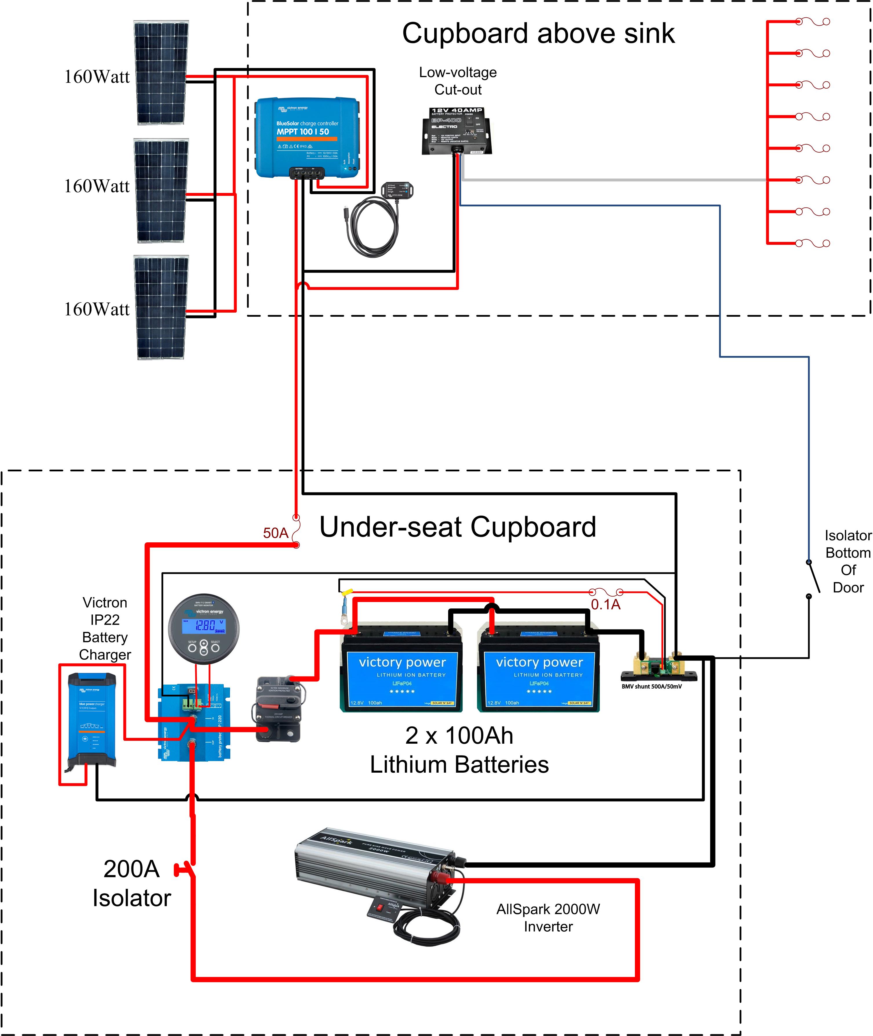
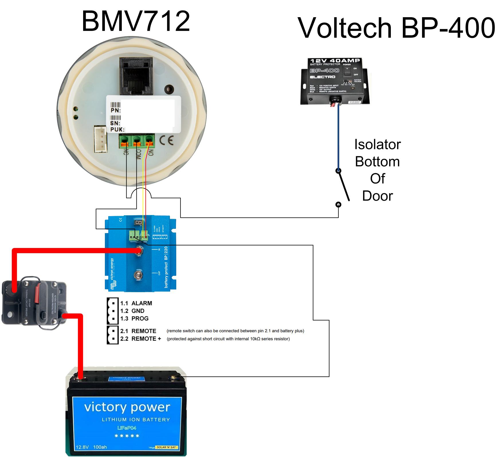
My Question is, looking at the picture below, I can get a pair of wires from the batteries, under the floor and over to the door switch that controls the Voltech, Unfortunately the Voltech uses negative wire switching and the BP 220 uses Positive switching.

I use the normally closed contact to open at 25% capacity.

If I connect the BP220 terminals 2.1 and 2.2, BMV and connect the Voltech control wire as shown in the picture below, I believe I could achieve this what I want but it really depends on the manual being right for connection 2.2 as the BMV would connect both terminals to battery negative.

In normal operation the BMV N/C contacts provide a circuit to the Voltech via the RV isolator switch inside the door and the BP 220 is enabled with 12V on terminal 2.1.

When the BMV goes below 25% capacity, the relay changes state and removes the battery negative so the Voltech cannot enable and the BP 220 terminals are now at battery negative so it should disable the BP220.

I would think the BP 220 should be able to operate indefinitely with its terminal 2.2 shorted to battery negative - is this correct.

Battery Protect
context.jpg (635.0 KiB)
proposed.jpg (162.6 KiB)
context.jpg (636.5 KiB)
2 |3000

Up to 8 attachments (including images) can be used with a maximum of 190.8 MiB each and 286.6 MiB total.

4 Answers
Paul Skelly avatar image
Paul Skelly answered ยท

Hi,

I just wanted to advise, the method of switching the BP220 with the BMV using negative battery supply instead of positive battery supply and controlling the Voltech unit as described in my post and the Schematics above - all works perfectly.

I tested it today.

When both 2.1 and 2.2 are shorted together to negative battery potential, the BP220 is disabled. There is only 1.2mA drawn from the BP220 terminal 2.2 so it should be only minimal extra current draw when shutdown as I will be switching off the load when there is 25% capacity left in the batteries.

It use the Victron BP-65 - an obviously better option - in my RV.

Paul


2 |3000

Up to 8 attachments (including images) can be used with a maximum of 190.8 MiB each and 286.6 MiB total.

jwfrary avatar image
jwfrary answered ยท

if you have your yellow and red headed to the same terminal of the bp220 then it won't have any effect, its just shorted always. and in relay mode will never operate!

2.1 goes to batt pos to operate, but power best taken from 2.2.

2 |3000

Up to 8 attachments (including images) can be used with a maximum of 190.8 MiB each and 286.6 MiB total.

jwfrary avatar image
jwfrary answered ยท

i haven't looked it up but the batteries have internal bus I'm guessing.


so connect the MPPT direct to the battery or to the batt post of the batt protect. Then you can switch everything though one low voltage protection device.

2 |3000

Up to 8 attachments (including images) can be used with a maximum of 190.8 MiB each and 286.6 MiB total.

Paul Skelly avatar image
Paul Skelly answered ยท

Thank you @Jwfrary for your comments - it is appreciated.

I cannot find any information on these batteries so do not know what capabilities the internal BMS will have and I would rather avoid the BMS operating.

I was hoping to use the battery positive from BP220 terminal 2.2 that the manual says includes short circuit protection via a 10 k ohm resistor. Terminal 2.2 should act as a pull-up to battery positive.

When the BMV N/O contact is closed, shouldn't it connect both 2.1 and 2.2 to battery negative (by BMV Common). Then the BP220 terminal 2.1 will be at battery negative and disable the BP220.

I don't want to risk the internals of the BP220 by testing it on a new BP220.

I was hoping someone else had used the "pull-up" functionality of BP220 terminal 2.2.

Paul

1 comment
2 |3000

Up to 8 attachments (including images) can be used with a maximum of 190.8 MiB each and 286.6 MiB total.

jwfrary avatar image jwfrary commented ยท

@Paul Skelly

I think your miss understanding what the terminals are. The BP is a solid state relay so currents in the switch gear are really low.

Port 2.2 is positive as you say short circuit protected.
port 2.1 is negative, and your just supposed to have a switch or bmv relay across them.

You can opt to just use the port 2.1 and connect a battery positive to it.


0 Likes 0 ยท