question

colin avatar image
colin asked

CCGX restarts when contactor to charger switches

Update 30 Nov - So, having had apparently fine operation since installing the SSR. The ccgx suddenlty started frequently and apparently randomly restarting, then just wouldn't come on at all. Turns out the fuse holder on the + supply was cracking and the connection was bad... Hence I'm accepting JohnC's answer. My guess is something about when the contactor switched was exacerbating issue.

-----------

Update 19 June - I ended up installing a Fotek SSR-40 type solid state relay in place of the contactor, driven by the battery bank. So far so good! Unfortunately it means I'm not able to confirm any of the answers given below, though I'm sure they're right!

-----------

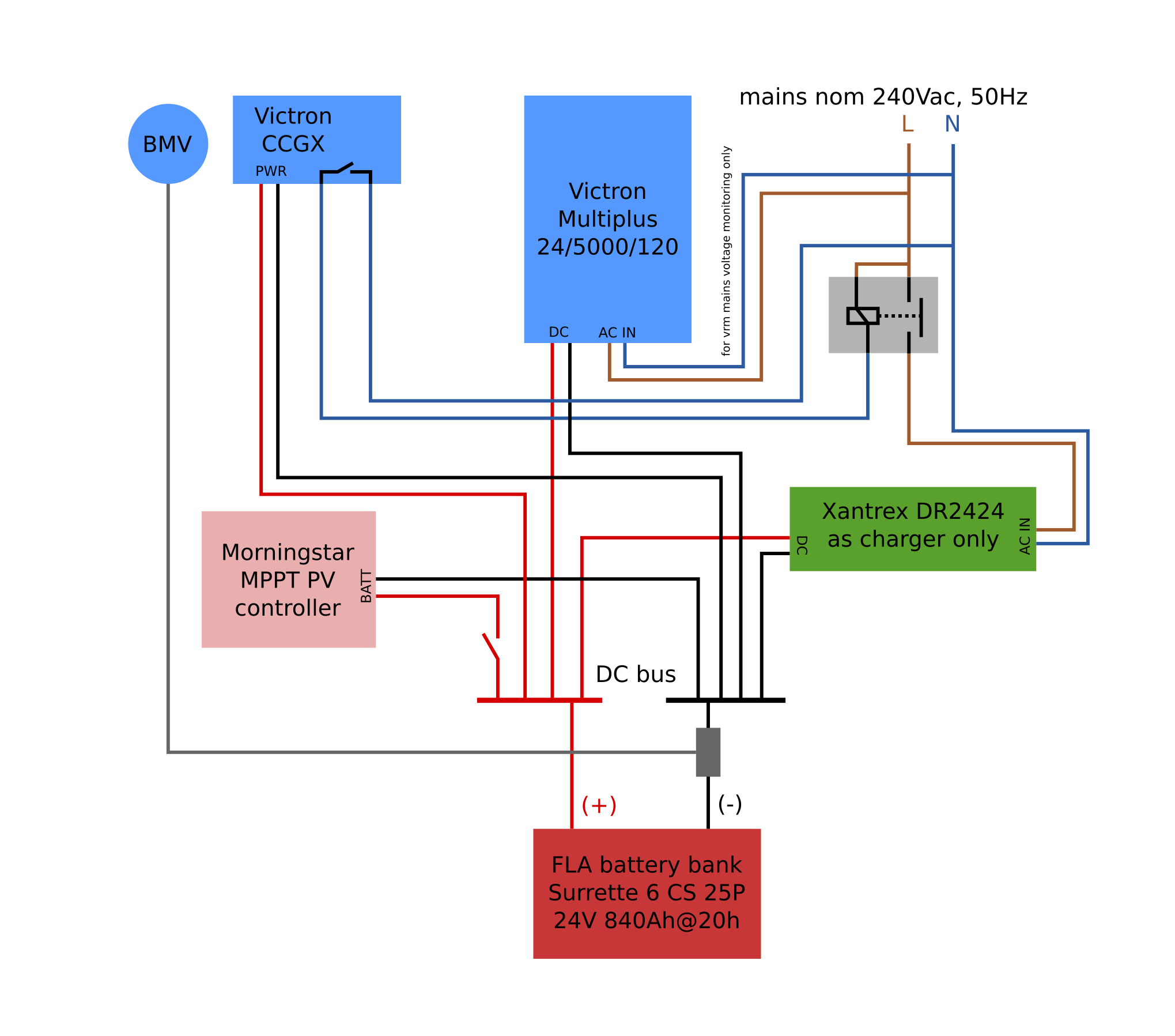
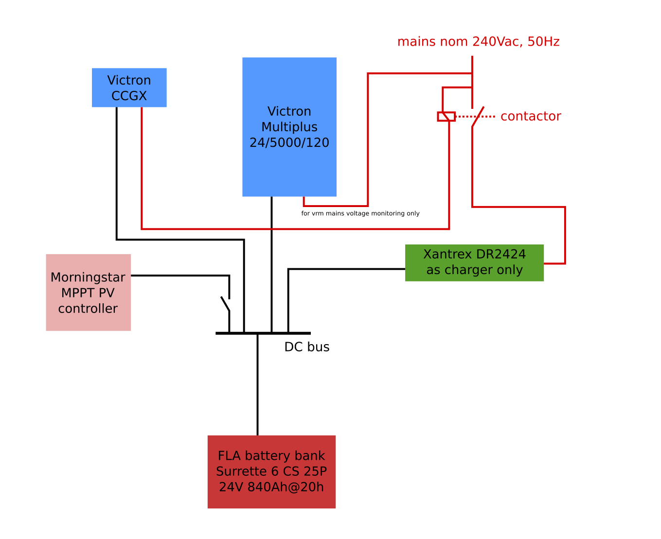
Please see image below for overview of the system.

The CCGX relay output is used with generator control to switch a charger based on SoC. Mains supply voltage is unreliable/variable, hence this configuration.

I've noticed often (but not always) the CCGX will restart itself when the contactor is switched off. This has been the case for perhaps 2 years now (I keep "meaning" to do something about it!).

Today, there was an apparent further progression of this problem, which I have not seen before. The system became stuck in a loop: contactor switches on -> small delay before xantrex starts charging -> ccgx trips/restarts -> contactor switches off due to ccgx turning off -> repeat.
I was able to break the loop by turning off the mains briefly until the ccgx had restarted and settled, then turing mains back on.
In this case the loads on the Multiplus where quite high 3.5kVA at the time.

Inverter/battery cables are undersized - 35sqmm (Again, something I've been meaning to rectify!).

I realise I should probably sort this out first, but I wondered if anyone might have any further ideas?

Many thanks

CCGX Color Control
2 comments
2 |3000

Up to 8 attachments (including images) can be used with a maximum of 190.8 MiB each and 286.6 MiB total.

Kevin Windrem avatar image Kevin Windrem commented ·

Is the CCGX relay rated for AC mains voltages?

Even if it is, there could be a possibility that the voltage spike when opening the CCGX relay could be causing enough EMF to crash the CCGX. It is probably best to use a second relay to drive the contractor. The second relay would run off the 24 volts from the battery and have a diode across its coil to quench the turn-off spike.

Since the CCGX will run on 12 volts or less, I doubt a sag on the DC bus could be the cause of the CCGX reboot.

I'm sure you have reasons but a couple of things in the design look odd to me:

Your diagram shows the mains connection to the Multi is only for mains monitoring. Is there something about the Multi's charger that causes issues with this configuration?

Is turning the Xantrex on and off necessary? Can't it's charging current be added to the Multi and solar contributions? You have a BMV so it seems like you can use DVCC to insure the charging current does not exceed what the battery can tolerate even if the CCGX can't control the Xantrex and MorningStar.

0 Likes 0 ·
colin avatar image colin Kevin Windrem commented ·

Hi Kevin, thanks for your comments.

I will try the additional relay.

Our mains supply voltage is quite erratic, usually low. I prefer to use the steady output of the Multiplus, rather than have it pass through the mains supply. I still want to know what's happening with the voltage on vrm so I have connected it to the Multi's input, but in the settings have prevented the Multi from ever connecting.

My reasons for turning on/off the Xantrex:

- off from 10pm as it is noisy and close to our bedrooms

- allow a little bit of battery discharge to make best use of solar - not sure if this isn't false attempt at economy, but I like to imagine the solar being used and not going to "waste"!

- the xantrex uses tail current to determine when to go to float - so it either does so too soon or too late depending on what's happening on the dc bus. I can better manage it with switch on/off

0 Likes 0 ·
2 Answers
JohnC avatar image
JohnC answered ·

Hi @Colin

Might this be related to interruption of the CCGX's 'Power in V+' supply?

It's described here in Section 1.3 https://www.victronenergy.com/live/ccgx:start


1 comment
2 |3000

Up to 8 attachments (including images) can be used with a maximum of 190.8 MiB each and 286.6 MiB total.

colin avatar image colin commented ·

Thank you JohnC. I did wonder if perhaps the sudden transition of charging current when the contactor switches off could cause a brief voltage fluctuation on the DC bus to trip the CCGX. But the multiplus seems untroubled (no flickering of lights for example).

0 Likes 0 ·
wkirby avatar image
wkirby answered ·

What sort of contactor are you using?

My immediate suspicion is that the back EMF generated when the contactor coil switches off is upsetting the CCGX. This back EMF of a few KV could be coming down the line and arcing the relay contacts inside the CCGX as well a causing a reset.

Usually a clamping diode (AKA flyback diode) is used to suppress the high Voltage back EMF. If the contactor does not have one inside it, then you are supposed to fit one close to the coil.

6 comments
2 |3000

Up to 8 attachments (including images) can be used with a maximum of 190.8 MiB each and 286.6 MiB total.

That was my first guess too, but he seems to be using an AC relay.

Still could be due to some EMF effect. But a better diagram is needed as this one obviously is incomplete.

0 Likes 0 ·
colin avatar image colin commented ·

Thanks WKirby and Daniël. It is a big 3 phase LC1 D2510 contactor (I'm only using one contact). This sounds very likely to me. I guess today's incident could be a result of gradual deterioration of the affected circuit in the ccgx?

I will have to make a plan. The system has been cobbled together over many years, transitioning from off-grid to on-grid and at minimum cost using whatever was available, so could really do with a major refresh.

Would you be able to specify a suitable clamping diode, eg if I need a stop gap (for the next 10 years :D).

0 Likes 0 ·
Daniël Boekel (Victron Energy Staff) avatar image Daniël Boekel (Victron Energy Staff) ♦♦ colin commented ·

@Colin

Please update your diagram, as it is still not clear how you drive your relay...as you've drawn it your relay coil is between DC ground and AC line...

that relay is also available in all kind of voltages, so that doesn't help much.

0 Likes 0 ·
colin avatar image colin Daniël Boekel (Victron Energy Staff) ♦♦ commented ·

Hi Daniël, I have edited my post with a more detailed diagram. Relay has 240Vac coil. Thanks

0 Likes 0 ·
Daniël Boekel (Victron Energy Staff) avatar image Daniël Boekel (Victron Energy Staff) ♦♦ colin commented ·

Hi @Colin

That's much clearer now.

Not sure what happens, but to test I'd use a smaller relay to drive the big relay

(yes. a relay driving a relay driving a relay)

This to know if it's somehow an EMC pulse coming from relay coil, or a result of switching the charger.

When this helps, you could try a shielded cable from GX device to the relay, and/ or running the AC wiring away from other cables from/to the GX unit.

0 Likes 0 ·
colin avatar image colin Daniël Boekel (Victron Energy Staff) ♦♦ commented ·

Thanks Daniël

0 Likes 0 ·