question

outbackandy avatar image
outbackandy asked

EasySolar-II GX and ECO4840P batteries

Hello to all,

Can anyone please advise if the EasySolar-II GX will integrate properly with PowerPlus Energy (Aust) ECO4840P battery banks that have built in proprietary BMS with no communications capability?

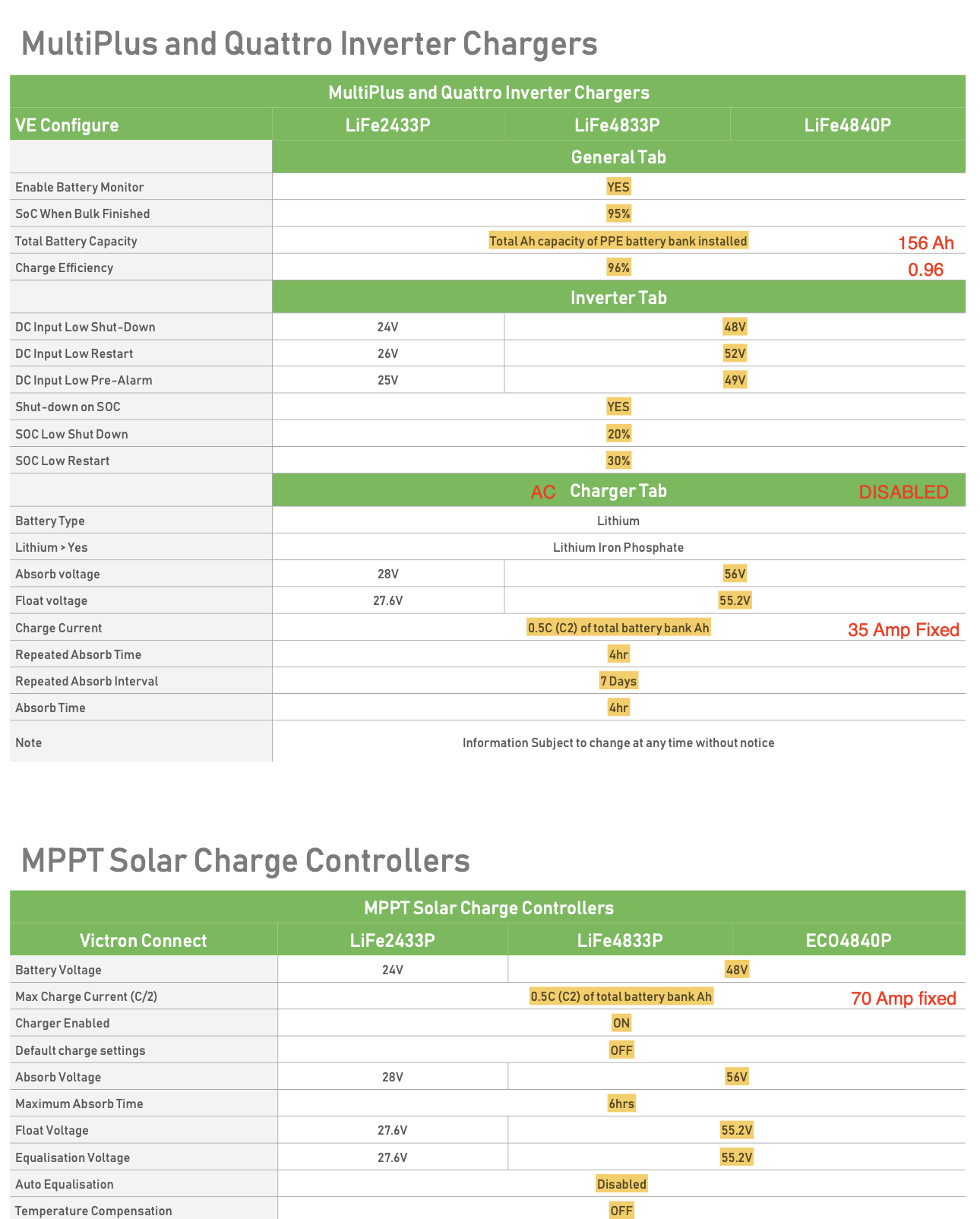
The ECO4840P's are not listed in the Victron Battery Compatibility list however PowerPlus Energy state that model ECO4840P is compatible with Victron but there is no clear statement about working specifically with EasySolar-II.

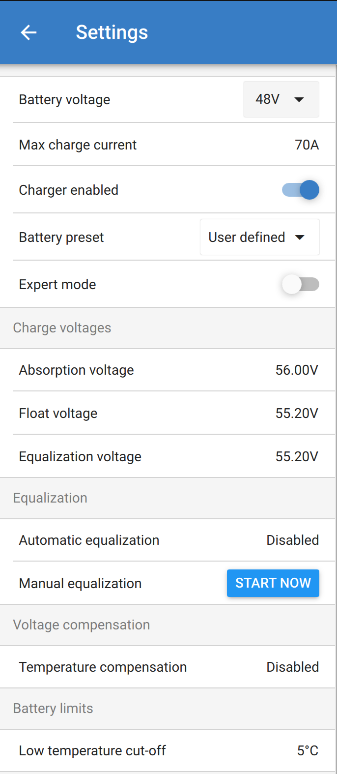
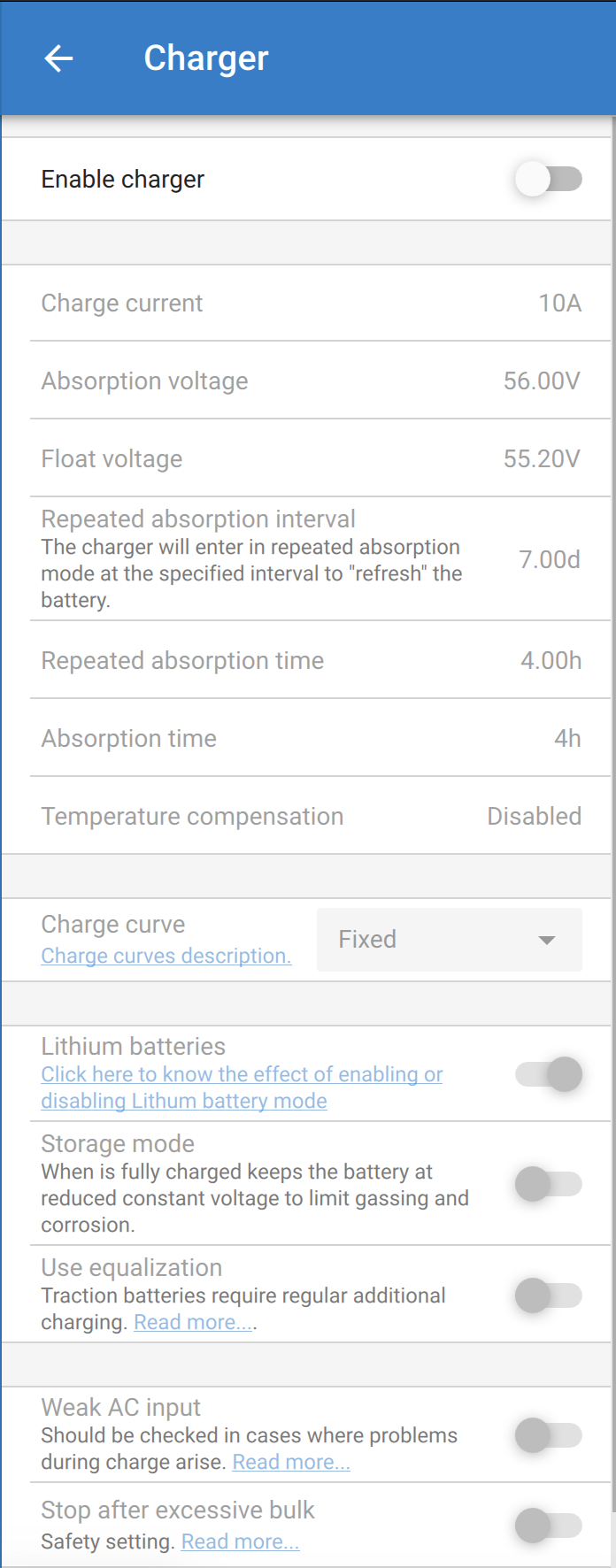
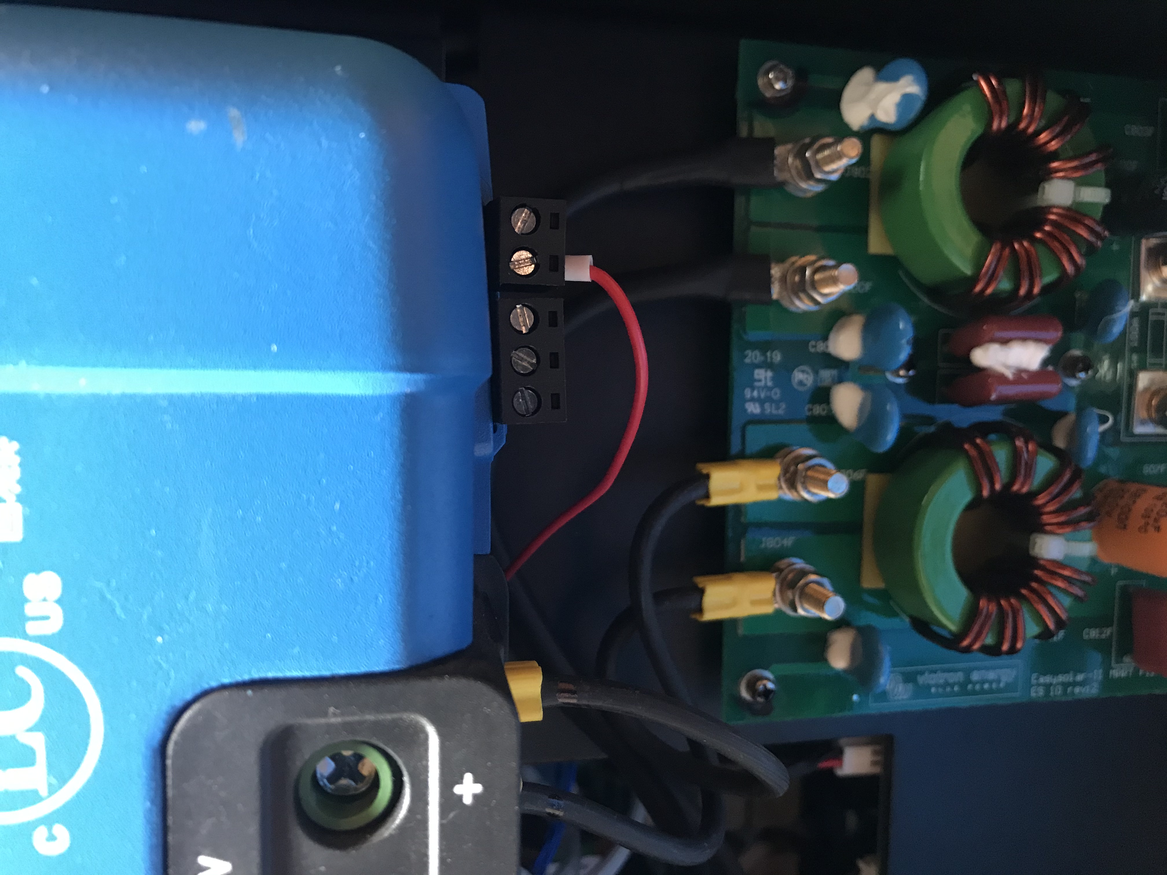
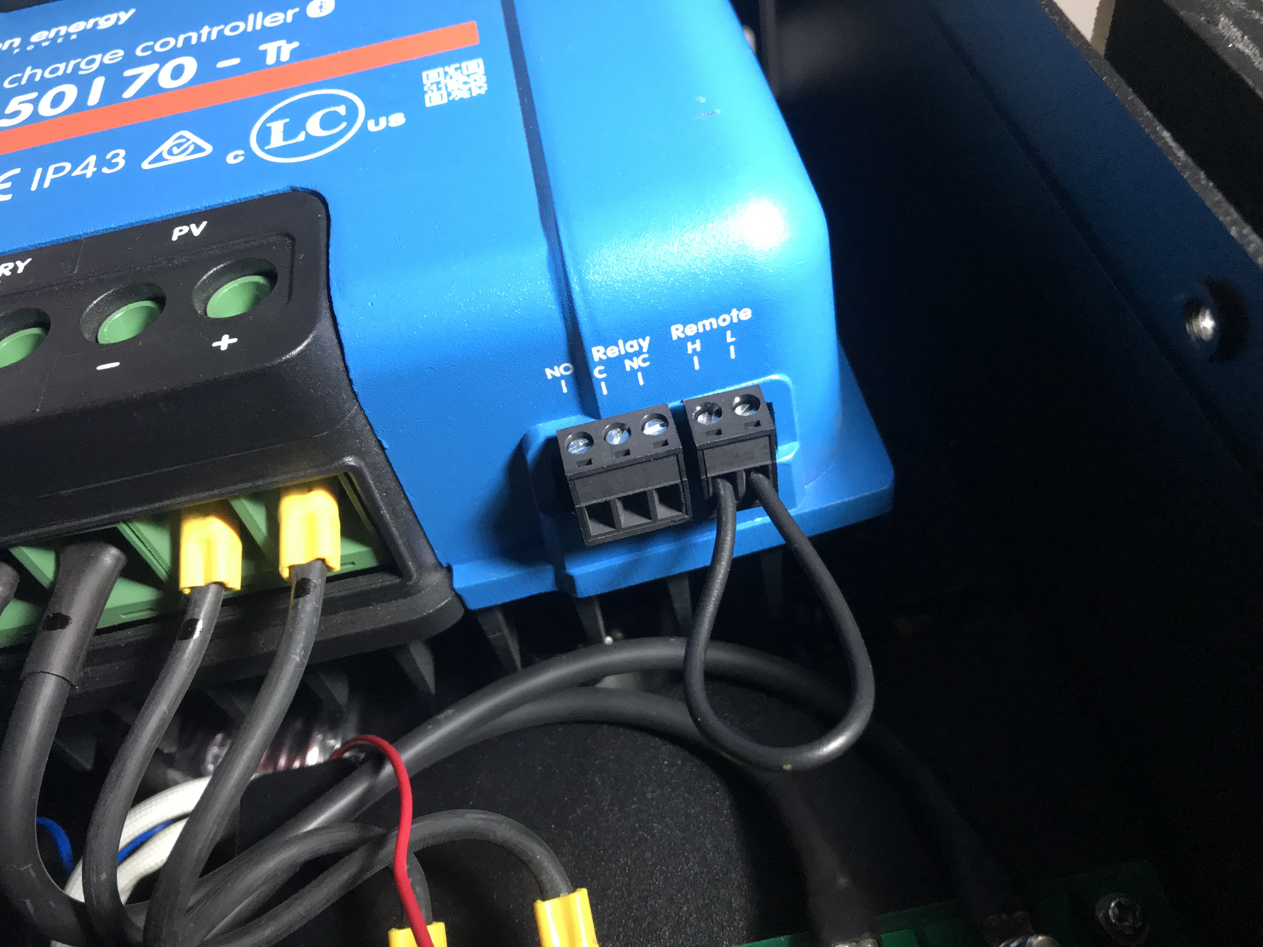
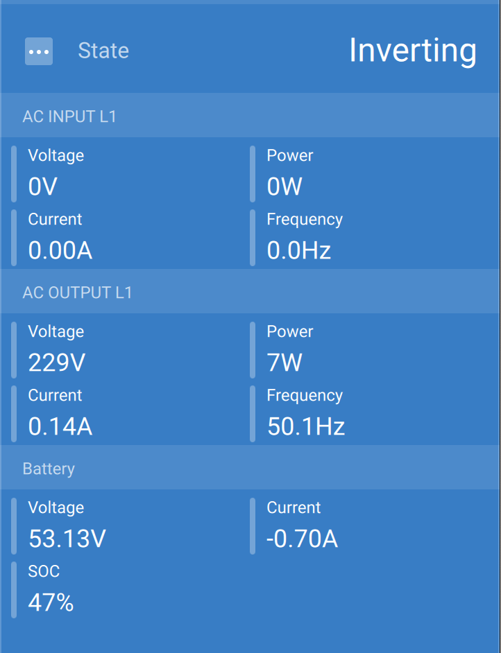
My new EasySolar-II system is fully connected to 2 x ECO4840P's and the EasySolar MPPT charger is being held in OFF state by the GX device.

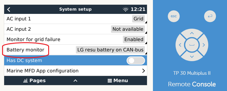
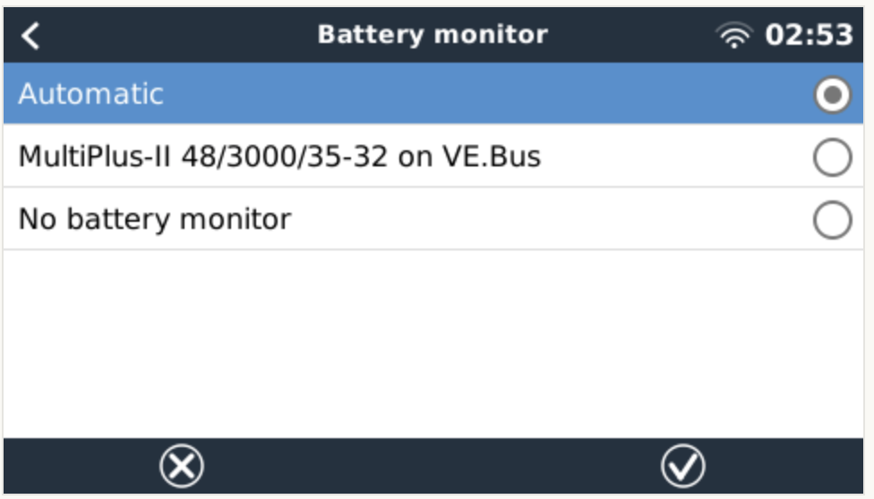
Just wondering if it's because the GX can't talk to a BMS?

Any advice appreciated.

Kind regards Andrew.


EasySolar All-in-Onemppt charging
2 comments
2 |3000

Up to 8 attachments (including images) can be used with a maximum of 190.8 MiB each and 286.6 MiB total.

ejrossouw avatar image ejrossouw commented ·

@OutbackAndy Not sure whether you saw Guy's reply?

0 Likes 0 ·
outbackandy avatar image outbackandy ejrossouw commented ·

@ejrossouw Yes, thank you for advocating the issue and eliciting a response. Guy's information answers my question and I'm now happy to leave my MPPT remote control loop wire installed, and the factory wiring disconnected.

Thanks to all who contributed in this discussion. cheers, Andrew.

0 Likes 0 ·
3 Answers
ejrossouw avatar image
ejrossouw answered ·

Hello @OutbackAndy Without knowing your settings, it is hard to tell. What is the battery voltage as maybe the batteries have shutdown? Does the inverter charge the batteries ok? Is the system grid connected etc.?

3 comments
2 |3000

Up to 8 attachments (including images) can be used with a maximum of 190.8 MiB each and 286.6 MiB total.

outbackandy avatar image outbackandy commented ·

Hi, thanks for your interest. Further system information:

* No Grid connection and no alternate AC charger. Features disabled in GX device.

* All firmwares are up to date.

* Lipo battery settings in MPPT and MultiPlus are set as per manufacturers specs.

* Battery voltages sitting at 54VDC in a 48V system.

I can force the MPPT into normal charge cycles by disconnecting MPPT remote input that comes from GX card and then looping MPPT remote input. This however defeats the factory wiring which I'm not happy about doing. The whole system seems to work once I disconnect GX's control line to MPPT. With factory wiring re-instated the MPPT is stuck in OFF state due to it's remote input being in low state. I'm searching for reasons why the GX would inhibit the MPPT charging for example lack of BMS. cheers, Andy.

0 Likes 0 ·
ejrossouw avatar image ejrossouw outbackandy commented ·

I thought these are Lithium batteries? If so, if set to lipo it could be part of the problem. That has to be same on the inverter. If you can do some screenshots it would be great.

0 Likes 0 ·
outbackandy avatar image outbackandy ejrossouw commented ·

The batteries are self managed Lithium Ferro Phosphate and I have set the MPPT and MultiPlus settings according to manufacturer's specs.

MPPT battery settings:

MultiPlus General settings

MultiPlus Inverter settings

MultiPlus Charger settings. Disabled as there is no AC source.

Manufacturer's settings for battery highlighted. My markups in red.

0 Likes 0 ·
ejrossouw avatar image
ejrossouw answered ·

@OutbackAndy I cannot see anything obvious. What happens if you enable the charger on the EasyII? Do you run DVCC? Not sure what you mean by looping. Using another cable to connect to the EasyII externally? Could it mean a faulty internal connection although unlikely if the MPPT shows up in the device list.

7 comments
2 |3000

Up to 8 attachments (including images) can be used with a maximum of 190.8 MiB each and 286.6 MiB total.

outbackandy avatar image outbackandy commented ·

@ejrossouw, I have previously enabled the MultiPlus charger and it made no difference to MPPT being stuck in OFF state. The system is not configured to use DVCC. I have included 2 photos that hopefully illustrate wiring changes I made to over-ride GX device remote control of MPPT.

Photo 1 - Factory wiring of MPPT remote control where MPPT is stuck in OFF state. The red wire seems to connect to the GX device and the MultiPlus.


Photo 2 - I have disconnected the red GX remote control wire and looped the MPPT remote inputs with a black wire. In this state MPPT charges batteries normally. ie Bulk->Absobtion->Float.

Cheers.

0 Likes 0 ·
img-1921.jpeg (1.8 MiB)
img-1920.jpeg (1.9 MiB)
ejrossouw avatar image ejrossouw commented ·

@OutbackAndy

You checked most of these I believe.

"The charge controller does not charge the battery. The LCD-display indicates that the chargecurrent is 0 Amps. Check the polarity of the solar-panels. Check the battery breaker Check if there is an error indication on the LCD"

What 1. are the VS settings configured as on the EasySolar-II 2. what is set as the battery monitor?

"The on/off mechanism of the MultiPlus-II also controls the SmartSolar MPPT." which makes sense to ensure all power is off when the inverter is off.

"3.5 Remote on-off The left terminal is connected to the internal 3,3V supply, with a resistor in series for short circuit protection. The right terminal (marked as + or marked as H) will switch the controller on if >3V is applied, and will switch the controller off if <2V is applied or if the terminal is left free floating. The recommended use of the remote on-off is: a. A switch wired between the left and right terminal b. A switch wired between battery plus and the right terminal. c) A switch between the right terminal and the charge disconnect terminal of a VE.Bus BMS"

From the above and your photo, I'd expect the wire should be connected to the right connector +(H) to received a >3V input from the GX to turn it on. Maybe worth checking the voltage on that cable and double check with Victron.


0 Likes 0 ·
1588332332076.png (38.3 KiB)
outbackandy avatar image outbackandy ejrossouw commented ·

@ejrossouw

I have checked troubleshooting suggestions for when MPPT does not charge. When black loop wire is in (Photo 2 previous comment) the system works so solar polarity correct, breakers OK, no error on LCD.

1. VS settings ? I'm not familiar with these settings, can you please advise where to find these settings.

2. Battery monitor choice - set to Auto as per photo attached. The system only detects one Battery Monitor being the MultiPlus.


The on/off mechanism of the MultiPlus-II also controls the SmartSolar MPPT." which makes sense to ensure all power is off when the inverter is off.

The above statement is interesting as it suggests the MultiPlus is in control of the red remote control wire to the MPPT and not the GX device like I assumed. The inverter is switched on and running.

Under what other circumstances would the MultiPlus want to inhibit MPPT operation?


The red remote control wire was connected correctly to the 'H' term as per manual. In my case when viewing MPPT from the front the 'H' terminal is on the Left - see photo

cheers.

0 Likes 0 ·
ejrossouw avatar image ejrossouw commented ·

@OutbackAndy To get into the inverter settings you can use a mk3 usb cable and PC or do it via the VRM portal. Not sure whether these are options for you?

When was the system installed and did the installer not ensure it was properly configured prior to commissioning everything tested after?

1. The inverter does not control the mppt and if there was no GX device, there would be no comms between mppt and inverter.

2. I don't know where the MPPT switch connects to the GX or what controls it there so hopefully some Victron support person can help out on this. Can you measure the voltage on that cable?

What is the setting for the relay?

Somehow I agree that in the absence of a bms connection (external a least) a setting in the GX is not enabled.

This is a touch beyond me as I have not personally fiddled with a new GX inverter yet.

0 Likes 0 ·
outbackandy avatar image outbackandy ejrossouw commented ·

@ejrossouw I have a MK3 usb cable for configuration using VictronConnect and I have also fully setup the VRM Portal option and have spent many hours going through each and every setting for MPPT, MultiPlus and GX device.

I have been through all inverter (MultiPlus) settings using VictronConnect and can't find any relay setting options at all.

I have also been through all the GX device settings using web browser and same, can't find any relay setting options at all.

It seems we have exhausted our knowledge so special thank you for your suggestions and advice. If I find anything further I will post back here. Cheers, Andrew.

0 Likes 0 ·
Leslieanne avatar image Leslieanne outbackandy commented ·

Hi Andrew, maybe a dumb suggestion, but have you checked the voltage on the H and L terminals on the mppt? Could they have been mislabelled in manufacture and the H is indeed on the right as per the description? Your loop connector would still work in that case too. Worth checking voltage on the red wire as already suggested. If it is less than 3V when mppt should be charging, then the problem is definitely with the control side. Cheers, Leslie

0 Likes 0 ·
outbackandy avatar image outbackandy Leslieanne commented ·

@Leslieanne Hi Leslie, thank you for your interest. You raise a good point about mislabeling given the manual explicitly describes the functions of the left and right terminals on the MPPT as being L & H. Maybe it depends on whether you are looking bottom up or top down?

I have previously measured voltages on red wire and MPPT terms and just to be sure I re-measured them just now.

- The red wire sits at 0 VDC while disconnected.

- If I reinstate the red wire to factory standard in the H term it reads 0 VDC.

- The black loop wire (H&L) sit at 9.4 VDC while connected.

- The H term measures 0 VDC while unconnected.

- The L term measured 12.7VDC while unconnected.

All voltage readings were measured in respect to the battery minus term.

The measurements suggest H & L term functionality is correct. The H term requires >3VDC for the MPPT to switch from OFF state to operating.

Thanks and cheers, Andrew.

0 Likes 0 ·
Johnson Lee avatar image
Johnson Lee answered ·

We've installed a few PowerPlus Energy (PPE) lithiums with Victron for customers and the PPE batteries do not need any setting changes other than the Victron document listed on their website as the PPE batteries are unmanaged batteries. Make sure the MultiPlus LVD is set to what they want or the BMS will cut out.

The Remote On/Off should be looped on the MPPT as the abs/float voltage setting is lower than the BMS high voltage cut off.

Also another thing to note is the PPE Eco batteries are rated to 39A @ 48V continuous and 63A surge. 2 ECO's might not be sufficient to run your MultiPlus (unless its the 3000VA model).

6 comments
2 |3000

Up to 8 attachments (including images) can be used with a maximum of 190.8 MiB each and 286.6 MiB total.

outbackandy avatar image outbackandy commented ·

@Johnson Lee Hi, I have configured MultiPlus and MPPT settings as per PPE's LiFe and ECO series REV 02 document from their Website.

I have LVD (DC input low-shutdown setting, MultiPlus Inverter tab) set to 48V and the battery banks voltage is at about 54VDC so still plenty of margin there.

Can you please clarify your statement about "Remote On/Off should be looped on the MPPT" as the EasySolar unit does not come configured that way. Is it a requirement to remove the factory fitted red remote control wire and install a remote loopback wire on the MPPT when using ECO batteries?

The EasySolar unit is indeed a 3000VA model so hopefully 2 x ECO battery modules should be sufficient.

Thanks for your suggestions and advice. Cheers and regards, Andrew.

0 Likes 0 ·
Johnson Lee avatar image Johnson Lee outbackandy commented ·

The pictures you've attached in the other posts indicate you have already wired this loop for Remote on/off.

The cable from the factory connected onto the built in Venus GX/MultiPlus Relay is probably for use with Victron's own lithium battery and the other terminal triggered by the VE.Bus BMS.

0 Likes 0 ·
outbackandy avatar image outbackandy Johnson Lee commented ·

@Johnson Lee Yes, I disconnected the red factory wiring from MPPT remote pins and installed my own loop wire just to get the MPPT charging. However I was not happy about changing factory wiring without good reason and documentation to support change.

Your second statement is the exact information I'm looking for - that the red wire is probably for Victron battery products. I have not been able to find any documentation that spells this out clearly especially for cases where 3rd party self managed battery systems are integrated.

Thanks for your help and cheers, Andrew.

0 Likes 0 ·
ejrossouw avatar image ejrossouw Johnson Lee commented ·

@Guy Stewart (Victron Community Manager) @Daniël Boekel (Victron Energy Staff) @Johannes Boonstra (Victron Energy Staff)

Can we please obtain a little clarity from our gurus. Below looks like two different devices to me and this topic has now lead to a lot of guess work.

Also, for the GX specification it has no explanation on the programmable relay, which is N/A and (7) does not have an explanation, however below it appears to be connected to the MPPT remote control? 1. What is this connection for 2. Its function and 3. How is it controlled and by what? Will it indeed not close if there is not an external BMS connected to the multi?

Your valued input will be greatly appreciated at this point.

0 Likes 0 ·
1588419223760.png (78.5 KiB)
1588419262528.png (339.5 KiB)
1588419400464.png (9.5 KiB)
1588419580277.png (177.3 KiB)
1588419586830.png (177.3 KiB)
Guy Stewart (Victron Community Manager) avatar image Guy Stewart (Victron Community Manager) ♦♦ ejrossouw commented ·

Hi @ejrossouw,

Thanks for bringing my attention to this. The green I/O terminal strip on the MultiPlus-II section was a hardware revision which has not been fully updated in some of the images in the EasySolar-II GX manual. An oversight that I will fix this week.

Current EasySolar-II GX connection hardware is shown correctly here:

https://www.victronenergy.com/inverters-chargers/easysolar-ii-gx#pd-nav-secondimage


There is no user accessible programmable relay in the GX card (the GX device in the EasySolar-II GX). The relays on the unit actually belong to the MultiPlus-II.

The MPPT should work out of the box without a BMS. However if the Multi is programmed with a VE.Bus BMS assistant when one doesn't exist (which sometimes happens by an installers mistake) then you might disable the MPPT that way via software.

In the case of the Power Plus batteries (with their internal/no-signal BMS) it would also be fine to override that power signal, and loop the MPPT remote cable connection (as is normally done with a new MPPT out of the box).

I will be making an Online Training for Victron Professional with the EasySolar-II GX shortly, and will have more time to investigate out of the box behaviour with different battery configurations. As well as bring some more clarity to internal division of connections and system elements (MultiPlus-II, GX Card, & MPPT).

0 Likes 0 ·
ejrossouw avatar image ejrossouw Guy Stewart (Victron Community Manager) ♦♦ commented ·

@Guy Stewart (Victron Community Manager) Thank you for the prompt reply. This is a great help. I trust if the system is booted with the assist override it should provide an indication of a potential "rogue" assistant being accidentally configured if the MPPT kicks into life. Regardless, I agree the loop is a perfectly sound way forward, just not sure why it was wired in this way in the first place.

0 Likes 0 ·

Related Resources

EasySolar 1600 product page

EasySolar-II GX 3000 & 5000 product page

Additional resources still need to be added for this topic