question

alfonsohera avatar image
alfonsohera asked

Multiplus II GX & MODBUS TCP required configuration

The communication white paper describes the following configuration when using MODBUS TCP and a GX device:


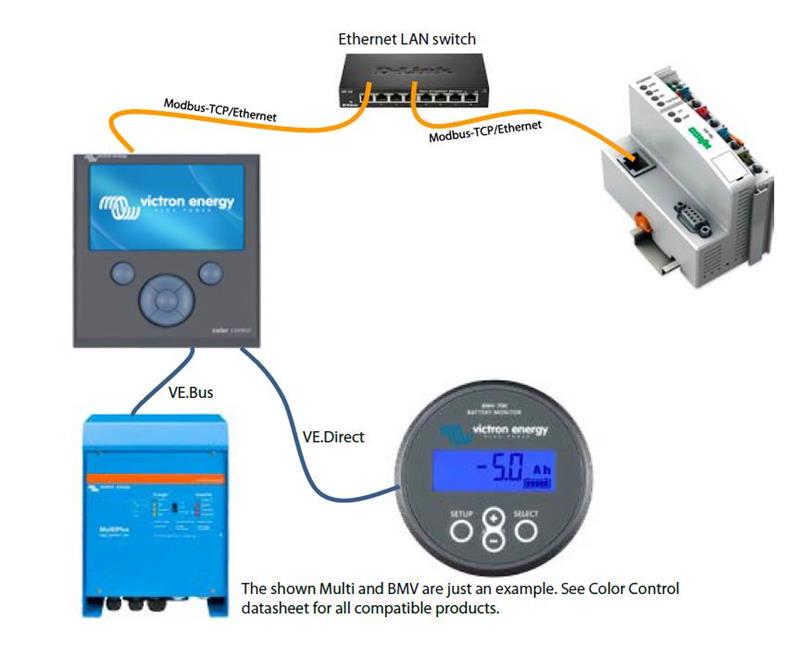
In this configuration a nework switch is used between the GX device (the MODBUS server) and another device (the MODBUS client).

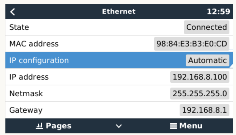
I'm trying to establish a communication channel between a Multplis II GX and an embedded device using MODBUS TCP. Until know I have tested the communication with my PC, and the device successfully sends the MODBUS payload on TCP frames. These messages include the Unit ID of the Multiplus (as well as the rest of the required fields), however I'm not sure how to address the Multiplus in a real test. Does it normally get an IP address from the network switch? Can I assign a fixed IP address that I can always use to send messages with my embedded device (or with any other device for that matter)? Do I absolutely need a network switch as part of the system?

Thanks,

Alfonso

Modbus TCP
1587393230310.jpeg (42.6 KiB)
2 |3000

Up to 8 attachments (including images) can be used with a maximum of 190.8 MiB each and 286.6 MiB total.

5 Answers
alfonsohera avatar image
alfonsohera answered ·

Sorry, I just realized this question might belong to the Modifications section

7 comments
2 |3000

Up to 8 attachments (including images) can be used with a maximum of 190.8 MiB each and 286.6 MiB total.

I'll move your question to there :)

And yes, the GX device can have a fixed ip address

0 Likes 0 ·
alfonsohera avatar image alfonsohera Daniël Boekel (Victron Energy Staff) ♦♦ commented ·

Hi Daniël, thanks for your reply. Could you elaborate more in how to proceed with this? Is there a way to hardcode a desired IP address in the Multiplus II GX? otherwise, how can one assign a fixed IP address to the Multiplus without the need of extra network equipment? My ideal configuration would interface directly using an embedded device.

0 Likes 0 ·
alfonsohera avatar image alfonsohera Daniël Boekel (Victron Energy Staff) ♦♦ commented ·

HI @Daniël Boekel (Victron Energy Staff), is there no official answer to my last question?. I would like to fully understand the constraints of the equipment I'm using right now.

0 Likes 0 ·
Daniël Boekel (Victron Energy Staff) avatar image Daniël Boekel (Victron Energy Staff) ♦♦ alfonsohera commented ·

Hi @alfonso.hera

Yes, Ethernet settings:

0 Likes 0 ·
alfonsohera avatar image alfonsohera Daniël Boekel (Victron Energy Staff) ♦♦ commented ·

Thanks for the quick reply @Daniël. That's something accessible via the Color Control GX right? Is there a way to do the same with the PC via the MK3-USB cable instead?

0 Likes 0 ·
Daniël Boekel (Victron Energy Staff) avatar image Daniël Boekel (Victron Energy Staff) ♦♦ alfonsohera commented ·

No, you have the MPII-GX, the GX card inside works about the same as a Venus GX (basically: a Color Control without the display)

https://www.victronenergy.com/live/venus-gx:start#accessing_via_the_local_lan_wifi_network

0 Likes 0 ·
alfonsohera avatar image alfonsohera Daniël Boekel (Victron Energy Staff) ♦♦ commented ·

Excellent, thanks! I'll try that.

0 Likes 0 ·
alfonsohera avatar image
alfonsohera answered ·

Thanks @Daniël , I was able to set the IP address of the inverter connecting it to my PC. With this, and after enabling Modbus TCP in the inverter's settings, I could start sending read and write messages to the inverter. However, the specific circumstances of my setup have lead to another "problem". The system is not intended to feed electricity back to the grid, but only use it to charge the batteries attached to the Multi. The batteries themselves are Lithium batteries that have a custom BMS. The embedded device would act as the interface between the BMS and the Multi, however the only registers available for the Multi that are writable and that would allow some control over the charging of the batteries are apparently ESS related. I can't enable ESS without choosing a grid code, but I don't really need the settings associated with feeding back to the grid.

In short: Is there any way to control the way the Multi charges my batteries? ie: sending charging voltage/current limits, and starting/stopping charge and discharge. I have done this in the past with another inverter from another company over CAN. I know that Victron has its own CAN BMS and that the protocol is not open, but I'm wondering if there is an option to achieve this without having to use a Victron specific product.

Thanks,

Alfonso

3 comments
2 |3000

Up to 8 attachments (including images) can be used with a maximum of 190.8 MiB each and 286.6 MiB total.

alfonsohera avatar image alfonsohera commented ·

Is there no official answer to this question @Daniël. After searching for information in this community platform my understanding is that the MODBUS TCP implementation, or the CAN BMS protocol for that matter, is not fully supported by Victron, however there is a significant gap of information that would be required to be filled for someone to implement things on their own just by reading the official information disclosed by Victron. It would be better if every limitation of the products would be clearly conveyed so that one does not lose time trying to do something that, given the available information, seems possible while actually might not be.

I also understand that not every user/installer of Victron's products would require this type of level of information but having proper documentation fully available would really serve the purpose of this community. Otherwise it is just about asking questions and hoping that someone somewhere has had the same questions and somehow found an answer.

And just as a disclaimer, the integration I am trying to achieve could be part of a commercial product which in turn would translate to direct profit from Victron. I know I am not the first person to do so and I certainly won't be the last, so an active support channel driven by Victron and not by the users would help everyone not just the users.

0 Likes 0 ·
Daniël Boekel (Victron Energy Staff) avatar image Daniël Boekel (Victron Energy Staff) ♦♦ alfonsohera commented ·

Hi @alfonso.hera

Victron tries to have as much protocols 'open' for everyone, but we are often also restricted by contracts with other parties.

The CANbus BMS protocol you could have found, as REC has it in their specs. I would always advice to use such available products when starting developing products.

http://www.rec-bms.com/datasheet/UserManual_REC_Victron_BMS.pdf

As for integration with Victron products, your Victron Sales Agent is your point of contact for that:

https://www.victronenergy.com/contact#sales-managers


Further on this question:

In short: Is there any way to control the way the Multi charges my batteries? ie: sending charging voltage/current limits, and starting/stopping charge and discharge. I have done this in the past with another inverter from another company over CAN.

Depending on what the other inverter brand was, the protocol might not be much different (check the REC manual)

0 Likes 0 ·
alfonsohera avatar image alfonsohera Daniël Boekel (Victron Energy Staff) ♦♦ commented ·

Thanks for the quick reply @Daniël, I understand the situation regarding opening protocols and contractual commitments. However, we already went through the recommended channel (a Victron representative) with all our expectations from an inverter/charger and we were led to the current configuration (Multiplus + MODBUS TCP), however support ended directing us to the official documentation (communications whitepaper, register list) which as I mentioned is insufficient. The realization that the protocol might not serve our initial needs came after actual testing with the inverter and after investing developing time to implement the interface from our side. In my opinion this could have been avoided if the documentation was clearer about the product's limitations, or if we had been told from the start that what we wanted to achieve was not possible this way.

Regarding the REC BMS protocol I have seen it before and compared to the one I used before (Studer XTM) and it's not the same. In principle this would not be a problem however while the Studer's CAN protocol is freely available, Victron's CAN protocol is not. REC's documentation is only partial as for instance it does not fully describe the content of the alarms/warnings message (16-bit bitfields). Furthermore while REC documents all the messages sent by their BMS, it is not specified if these are all the messages that can be sent (for instance there is no message that can directly control the inverter/charger operation as in switching them on or off), or what messages can be expected from the Multi. This protocol looks to be similar, if not the same, to the information about SMA's CAN protocol however, that protocol is also not freely available and from the available information there seem to be some differences between them would have to be clearly identified before attempting any integration.
This type of details can be the difference between a successful and reliable implementation and a failed one.

From what I have read Victron stopped officially supporting the integration of different CAN-BMSs to their systems and therefore the protocol is not available from Victron, however as I mentioned before I am not the first one to attempt this and won't be the last. Even if the end result is not a Victron supported solution it would be helpful nonetheless to have a clear view of what is possible with these devices that in the end we are buying from Victron.

0 Likes 0 ·
alfonsohera avatar image
alfonsohera answered ·

Hi @Daniël,

An update to my issue. I have been able to sort out the required ESS configuration to start using the Multi with our BMS using MODBUS TCP as the interface. So far I have been able to charge the batteries according to what the BMS expects by changing the Power setpoint (register 37) of the Multi. At the end of charge, disabling both charge and feed-in via the resgisters 38 and 39 put the Multi in Pasthru mode effectively ending the charging phase. However I noted that when I attempt to use register 33 (switch state) to change the state, it doesn't seem to react as expected. For instance, if I try to stop the charging by changing register 33 from 1 to 3 or 4 (charging only to on or off), charging doesn't stop. Furthermore, looking at the switch state via the remote panel (on my phone) shows that the switch state indeed doesn't change. However, if I change the state via the remote panel on my phone, the inverter does react and changes from passthru mode to off.

Is there an explanation to why this register doesn't seem to be set properly over MODBUS TCP? As a side note, whenever I try to start/stop charge I also set the following registers (as explained in ESS MODE 2 and 3):
Start charge:
Register 33 = 1 //Switch pos = Charge only
Register 37 = Charging Power [W]
Register 38 = 0 //Charge enabled
Register 39 = 1 //Feed-in disabled
**Stop charge (by end of charge):
Register 33 = 3 //Switch pos = On
Register 37 = 0 [W]
Register 38 = 1 //Charge disabled
Register 39 = 1 //Feed-in disabled
***Turn off inverter/charger (attempted while charging and after end of charge)
Register 37 = 0 [W]
Register 38 = 1 //Charge disabled
Register 39 = 1 //Feed-in disabled
Register 33 = 4 //Switch pos = off


**After the BMS send the request to stop charging the battery, it was attempted to change the switch position to ON, but it remained in charge only. However, since both charge and feed-in were disabled, the Multi state changed to passthru.


***When trying to turn off the Multi while charging, the above mentioned commands were followed by the BMS disconnecting the battery's output voltage as I assumed that the Multi would react to the commands. The result was an overvoltage due to the apparent drop in the battery voltage while the Multi was still in charging mode. In this situation, other devices that share the DC bus can get damaged as a result of this voltage overshoot.

It would be great to know how can one safely and reliably change the Multi state to off via MODBUS TCP.

Thanks,

Alfonso

4 comments
2 |3000

Up to 8 attachments (including images) can be used with a maximum of 190.8 MiB each and 286.6 MiB total.

Hi @alfonso.hera

Why are you using switch state to stop charging instead of 38/39?

Do you have any components in the system that might influence switch state? (what battery / bms type have you set in ESS assistant?)

Also, just thought of...what happens when grid fails, and unit goes in inverter mode, does your bms still shut the system down when needed?

on the DC overvoltage: well yes never disconnect the battery unless absolutely needed.

0 Likes 0 ·
alfonsohera avatar image alfonsohera Daniël Boekel (Victron Energy Staff) ♦♦ commented ·

@Daniël:
Why are you using switch state to stop charging instead of 38/39?
On a previous experiment with an electronic load instead of our battery, changing register 38 didn't have an effect on stopping charge. Only changing the switch state did.
Do you have any components in the system that might influence switch state?
What type of components do you mean? between our BMS and the Inverter there is another embedded device which acts as the communication interface (it handles the sending of the MODBUS TCP commands based on the BMS expected limits). During the assistant I chose a Lithium battery type and I set the voltage levels according to our battery.

what happens when grid fails, and unit goes in inverter mode, does your bms still shut the system down when needed?
Well, the BMS doesn't know, or care if the grid fails. It's only role is to safely charge and discharge the battery. The communication interface handles configuring the inverter, turning it on and off. If the battery can't be charged, it would switch the Multi to the ON state (which from what I have seen enables the inverter).

on the DC overvoltage: well yes never disconnect the battery unless absolutely needed.
Sounds obvious but in this specific case is not something that can be avoided completely. Our system is not supposed to be on all the time, therefore at some point it needs to be turned off. Turning off the batteries when there is no AC at the input of the Multi is no problem because it just turns off. Turning off the batteries when there is AC at the input of the multi, but its state is OFF is also no problem because it also turns off. Turning the batteries off when the Multi is charging the batteries is where I observed the problem. But as I mentioned before, I sent the corresponding commands to change the state of the Multi from charging to off via MODBUS TCP but the Multi didn't change its state and that's why when the batteries disconnected the overvoltage was observed.


0 Likes 0 ·
Daniël Boekel (Victron Energy Staff) avatar image Daniël Boekel (Victron Energy Staff) ♦♦ alfonsohera commented ·

Hi @alfonso.hera

I can only advice you to take one step at the time:

one step: make your battery / bms work with Victron system.

other step: make ESS work with Victron system

Now your doing both at the same time, and both steps are officially unsupported, the help I'm giving is already more than I'm supposed to give.


so please make both work well independent of each other, and then combine.

0 Likes 0 ·
alfonsohera avatar image alfonsohera Daniël Boekel (Victron Energy Staff) ♦♦ commented ·

HI @Daniël,

I understand, however if you have another look at the the whole thread you will see that getting my battery to work with the Multi without ESS (I don't understand why you say ESS is not officially supported by the way) is not an option because without it I can't use the functionality I want to use the Multi to begin with (controlling the charge of my battery).

The only thing I need is to clarify the information that Victron openly discloses. Since the provided documentation is not accurate or precise enough I am looking for such clarification here.

I know from experience that such an integration is possible without the official support from the manufacturer, but it's not ideal. Victron seemed to be different on this regard and it's disappointing to see that it's not the case.

0 Likes 0 ·
Alistair Warburton avatar image
Alistair Warburton answered ·

I cant help you with talking to a BMS, supportd or otherwise, or ESS configuration, but I do have an option for you.

I have just set up charge current control for one of my Multi's sprciffically becuse I couldnt get my head arround ESS and definatly do not want grid export enabled as that would likely break something.

The solution I picked, is supported, and is easy... Its just the charge current control assistant and, i my case the Cerbo GX relays.

I wanted to be able to control charge fro Modbus but also VRM and the local GX interface. By using the relays to modify the refrence voltage for Aux1, which is the input asociated with the current control assistant I can do that.

Its not pretty and with only two relays it only has 4 levels you can set, including 0, but that is enough for what I need. Had I used an external voltgae refrence any current between 0 and max would have been posssible.

I posted in mods what I had done, saying it was simple but effective and didnt understand why there were so many questions about charge controll/ESS and this type of approach wasnt getting mentioned.

Thread here

This was only last night, and so far I have only seen one comment, but that comment advised me to just use ESS !

I am all for intigrated/supported and I am a little worried I am missing the point somwhere and that ESS is the answer to most of my questions. If it is I am not finding documentation/comments that demonstrate that, quite possibly because I dont ask he right questions and or know ehere to look.

Untill the comment, earlier today, I didnt even know that ESS had an 'External' mode, you would think it would have come up in the many threads I have read.

This is in no way a recomendation, I am simply saying there is a supported way, all be it with caviats, and I cant get my head arround ESS either, so much so that I dont even know if I could/should be using it.

(If external mode takes out the automation but retains remote access to the setpoints I need, it will be a better solution than my diode relay thingy, and any other external refrence, by a long way)

2 |3000

Up to 8 attachments (including images) can be used with a maximum of 190.8 MiB each and 286.6 MiB total.

Alistair Warburton avatar image
Alistair Warburton answered ·

I just looked at the ESS manual 'again' and so far as I can tell HERE 'External mode will only do some of what I/you want and then only with an external control loop... I had discounted ESS as an option for these reasons without going any deeper.

Note... From the page above...

"The point of control is the AC..." "...maximum battery discharge current is ignored..."


This is what pushed me down the charge control riute in the first place.

I MUST have the unit in passthrough, when the charger is disabled, whilst retaining power assist on top of an AC limit that respects the device feeding the inverter.

(Bulk/float but with 0 charge current would have been ok but as 'Passthru' supports 'Assisting' it is the better/cleaner choice)


2 |3000

Up to 8 attachments (including images) can be used with a maximum of 190.8 MiB each and 286.6 MiB total.

Related Resources