With a 50 amp electrical system in my RV, I'd like to install a Multiplus 3000 inverter/charger. I have three Battle Born LiPO4 batteries in parallel. My shore power is a 4-wire and there are two legs on the distribution panel. One of the companies that sells Victron adds a "Smart Phase Selector" in their 50 Amp RV upgrade. Can I install the Multiplus 3000 without this added device?Will the inverter/charger work in this regard?
asked
Installing the Multiplus 3000
Please consult a suitably qualified electrician for confirmation/direction, but my understanding is that if you simply wire the Multiplus AC input to one of the active phases and neutral it should work fine, the 2nd available phase just wont be utilized.
You don't need a smart phase selector. It probably just looks at both sides and chooses the one that's under less load.
You can simply choose one manually, when you wire up the charger.
Of course, if that leg also has several roof air conditioners or other big loads, you might trip the shore breaker if they all spin up at the same time. So, choose carefully.
--Removed by moderator--
Please stop posting copy/paste answers full of referral links.
This is your first and last warning.
Hi cgjog182, while my installation is single phase 30A, I hope my installation experience can shed light on yours. I’ve upgraded my travel trailer’s 30A/120V AC system by installing a Victron Energy MultiPlus 24/3000/70-50 120V with the Color Control GX Remote Panel, BMV-712 battery monitor and battery temp. sensor and 4 Surette Rolls 6V 250Ah AGM batteries wired in series to become a 24V battery bank (6.0kWh) with two Jinko Eagle PERC JKM365M-72-V 365W, 24V solar panels wired is series to supply 730W @ 48V to a Victron MPPT 100/50.
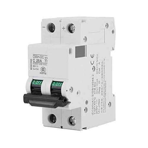
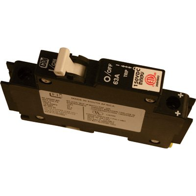
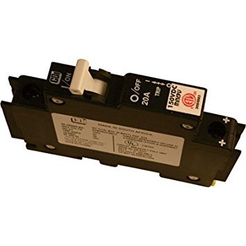
I installed a MidNite Solar 20A 150VDC circuit breaker on the positive leg between the PV array and the MPPT a MidNite Solar 63A 150VDC Circuit Breaker on the positive leg between the MPPT and the Multiplus and a 25A 250VDC 2-pole circuit breaker installed as a disconnect for the PV array and MPPT negative leads.
As the 24V battery bank leads run 15' from the Multiplus, I used 2/0 AWG fine strand copper cable. One positive line and one negative line, twisted together along the run to reduce inductive resistance and IR interference. All other DC connections were done with 6AWG fine strand copper cable.
I installed the inverter/charger in line with the shore power in-feed. That is, I wired the shore power in-feed through a 30A breaker then connected to the 120V AC input terminals of the Multiplus and the output terminals connected to the trailer’s 30A/120V AC panel.
This method is the simplest and least invasive integration with the trailer’s existing AC/DC system. Everything onboard operates the same whether connected to shore power or operating on solar/battery power. The existing IOTA DLS45 DC Converter (with the optional IQ4 Smart Charge Controller) remains in place providing 12VDC for onboard systems and smart charging for the 12V battery bank (2 6V, 230AH golf cart batteries wired in series) mounted on the reach.
While virtually all battery chargers will supply an AGM charge rate of around 15V for a 12V system and 29V for a 24V system, the significant factor is the charge rate amperage.
Rolls Battery recommends a battery string charge rate of 50amps. They also provide an AGM charge time formula:
t = 0.42 x (C/I) 2.1hrs = .42 x (250/50)
Where:
t = Absorption Charge Time (Hours)
C = 20 hr Rated Capacity (AH)
I = Charging Current (Amps)
The Multiplus provides a Bulk/Absorption charge at a solid 50 to 51amps, with the capability of supplying up to 70amps.
The charge rate amperage plays a critical role in system efficiency, especially in a solar PV array charging application. This is why I chose the Victron Multiplus and MPPT 100/50. By supplying the maximum allowable charge rate amperage, the charging time is minimized.
On my original installation of the Multiplus I didn't know/understand the central grounding point principal so the Multiplus was just operating off its case ground (to the chassis). The trailer shore power was connected to a 120VAC/15A receptacle on the side of the house. So, whenever I ran the trailer A/C, it blew that breaker. I was aware of, but didn't fully understand the PowerAssist function of the Multiplus. On the Victron website I found an illustrated diagram of a typical MultiPlus 24/3000/70-50 installation showing a negative bus bar central grounding point.

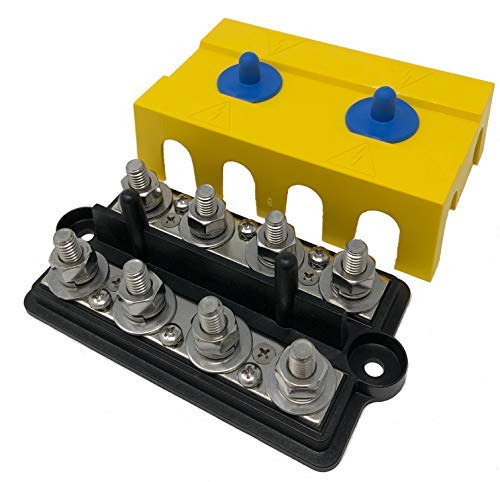
As I came to understand, it is critical for proper/safe system operation to install a central grounding bus bar with a single ground lead (sized to handle the maximum current) to the chassis. The battery bank negative terminal, the inverter/charger negative terminal and case bond, the MPPT negative terminal and case bond, the PV array negative terminal and case bond and ALL OTHER AC/DC neg./bond wires MUST be connected to the central grounding bus bar.
Also, the single grounding point to the chassis, the cable terminal lug, must be flat and bolted to a flat, bare metal finish on the chassis, no washers, star or otherwise in between. I used a flat smooth file to file the flat side of the cable lug flat and smooth as well as the flat point on the chassis, finishing with sandpaper. Once installed, I covered the connection with zinc rich primer. Recently, an electrician friend recommended applying an electrically conductive epoxy, silver adhesive (available on Amazon) between the lug and chassis to ensure/maintain maximum conductivity.
Further to this point, all my cable lugs are crimped and soldered with rosin paste flux and electrical solder. Not plumbing paste and solder. Terminal bolt type connections are torqued to 17N.m on the Multiplus and Bus bars and 10N.m on the Rolls AGM batteries. Loose or over-tightened connections may cause high resistance. The result is an unwanted voltage drop as well as excessive terminal heating, causing the terminal to melt or even catch fire.
I rewired everything as such and viola, the entire system started working properly AND is virtually silent.
Now the PowerAssist function operates properly, reading the 120VAC/15A shore supply and drawing additional power from the battery bank as needed, never blowing the 120VAC/15A shore supply breaker even with the fridge and A/C running. And, now the Multiplus essentially shuts down into Storage Mode when the load is under 20W (adjustable). As it turns out, the central grounding point provides the Multiplus with a voltage/current baseline reference point to calibrate/operate from which is essential for proper operation.
As I've learned, a system can operate/function in a less than ideal installation. When installed with research, attention to detail and workmanship, the system can perform to its maximum potential.
Cheers,
Glenn
I didn't read your whole post, but about this:
"Further to this point, all my cable lugs are crimped and soldered with rosin paste flux and electrical solder. Not plumbing paste and solder."
It very bad advice to solder connections, especially with fine stranded wire, and especially in applications where things vibrate.
Do not solder connections on RV's Boats, Cars, etc.
Solder forms a hard point in the cable, where the strands will break after a while
Hi Daniel, I respectfully disagree. I believe the conductivity gained by soldering far outweighs any potential for breakage. The soldered connection at the lug would have to be subjected to significant, repeated flexion to stress the stands to the point of breaking. The wiring in my mobile application is fixed secure and stable. Even when traveling, there is no flexion and/or vibration that would have any significant affect.
In my research for this project, I did not come across this concern for soldered connections. On the contrary, soldering (as I have described) was repeatedly recommended.
If you have additional information on the subject, I would be very interested in reviewing it.
Cheers,
Glenn
I'm not going to go into the details, every installer / electrician knows why not to solder connections.
In my opinion this is one of the best references for wiring terminations that's freely available. There's a section on soldering in there. He does note that the subject of soldering wires has been beaten to death on the net. :) Aside from that, it's a solid reference on crimping wires, and crimp tool selection.
https://marinehowto.com/marine-wire-termination/
Hi U2Yg735g,
Thank you for providing this informative article. I stand informed and corrected.
The origin of my belief that soldering a large gauge (2/0, 1/0) crimped terminal was a superior method, came from an AIMS Power inverter/charger installation manual that stated;
"Battery cables must be crimped (or preferably, soldered and crimped) copper compression lugs unless aluminum mechanical lugs are used. Soldered connections alone are not acceptable."
Seemed perfectly logical at the time. Going forward, I will invest in a quality crimping tool and leave soldering behind.
Cheers,
Glenn
Not only does soldering increases resistance in your electrical system, it does not allow for vibration and movement in a system installed in a vehicle. Cold weld crimping on luhs and use of high quality adhesive shrink wrap is the way to go. Too much solder rosen can also cause corrosion.